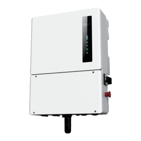
SOLIS S6-EH1P3.8K-H-US Product Manual
High voltage hybrid single phase residential energy storage inverter
Hide thumbs
Also See for S6-EH1P3.8K-H-US:
- User manual (94 pages) ,
- User manual (73 pages) ,
- User manual (62 pages)
Table of Contents
Advertisement
Quick Links
Advertisement
Table of Contents

Related Manuals for SOLIS S6-EH1P3.8K-H-US


Summary of Contents for SOLIS S6-EH1P3.8K-H-US
- Page 1 Product Manual High Voltage Hybrid Single Phase Residential Energy Storage Inverter Available Models: S6-EH1P3.8K-H-US S6-EH1P5K-H-US S6-EH1P7.6K-H-S-US S6-EH1P7.6K-H-L-US S6-EH1P10K-H-US S6-EH1P11.4K-H-US Version 2.4 Release Date: 12/02/2022...
- Page 2 ● Airborne noise produced depending on the environment. ● Potential flammability hazards. ● Solis will not be held liable for defects or malfunctions arising from: ● Improper use of the equipment. ● Deterioration resulting from transportation or particular environmental conditions.
- Page 3 Table of Contents Introduction Safety Overview Installation Commissioning Troubleshooting Specifications Appendix...
-
Page 4: Table Of Contents
Table of Contents 1. Introduction..................1.1 Inverter Description..................1.2 Included Components ..................1.3 Tools Required for Installation ................ 1.4 Inverter Storage .................... 2. Safety & Warning................2.1 Safety ......................2.2 General Safety Instructions ................2.3 Notice for Use....................2.4 Notice for Disposal ..................2.5 Protection Circuitry and Controls.............. -
Page 5: Inverter Description
PV power to cover load demand. This inverter can operate in both on-grid and off-grid applications. The Solis S6 hybrid inverter series consists of the following models: 3.8kW, 5kW, 7.6kW 10kW, and 11.4kW. S6-EH1P7.6K-H- -US has three MPPTs and S6-EH1P7.6K-H- -US has four MPPTs.The inverter comes equipped with an internal rapid shutdown transmitter. -
Page 6: Introduction
1. Introduction Mounting Bracket Hook DC Disconnect Switch DC Conduit Knockout Solis Data Logger (sold separately) Figure 1.3 Right Side View Mounting Bracket Hook AC Bypass Switch Rapid Shutdown Initiation Switch Solis Data Logger (sold separately) Figure 1.4 Left Side View... -
Page 7: Included Components
1. Introduction 1.2 Components Included with the Inverter If any of these items are missing, please contact your local Solis distributor or the Solis service team. Inverter Mounting Bracket x1 Stabilizing Bolts x2 Inverter x1 Ring Terminals x8 Torqx T20 Tool x1... -
Page 8: Inverter Storage
● Power up the inverter with a DC power supply annually for 5-10 minutes DO NOT STACK MORE THAN HIGH SAVE THESE INSTRUCTIONS – This manual contains important instructions for models: S6-EH1P3.8K-H-US, S6-EH1P5K-H-US, S6-EH1P7.6K-L-US, S6-EH1P7.6K-H-US , S6-EH1P10K-US, S6-EH1P11.4K-US, that shall be followed during installation and maintenance of the inverter. -
Page 9: Safety & Warning
2. Safety & Warning 2.1 Safety The following types of safety instructions and general information appear in this document as described below: DANGER “Danger” indicates a hazardous situation which if not avoided, will result in death or serious injury. WARNING “Warning”... - Page 10 NEC Article 690, Part II. All Solis single phase inverters feature an integrated DC disconnect switch. CAUTION Risk of electric shock, do not remove the cover. There are no serviceable parts inside, refer servicing to qualified and accredited service technicians.
-
Page 11: Notice For Use
Local waste management rules shall be observed and respected. 2.5 Protection Circuitry and Controls To meet relevant codes and standards, the Solis U.S. single phase inverter line is equipped with protective circuitry and controls. These include Arc Fault Circuit Interrupter (AFCI) and Anti-Islanding Protection. -
Page 12: Overview
3. Overview 3.1 LED Indicator Lights There are five indicator lights on the the Solis S6-EH1P(3.8-11.4)K-H-US Series Inverter: Battery, InverterWiFi, RS485 and Bluetooth. These lights indicate the working status of the inverter. The inverter creates a Bluetooth signal which is what the smart phone connects to so that the inverter interface page can be accessed. -
Page 13: Inverter Wire Box And Connection Points
Conduit for battery conductors should be connected here 3. Battery 4. Solis Logger Solis data logger gets connected here - only USB versions of the loggers will work Conduit for AC conductors to backup loads panel should be connected here 5. AC-Backup Conduit for AC conductors to the main service panel should be connected here 6. -
Page 14: Installation
4. Installation 4.1 Select a Location to Install the Inverter When selecting a location for the inverter, the following criteria should be considered: Exposure to direct sunlight may cause output power derating due to overheating It is recommended to avoid installing the inverter in direct sunlight. The ideal location is one where the ambient temperature does not exceed 40C (140F) It is also recommended to install the inverter somewhere the rain and snow will not land directly on it. - Page 15 ● Consult the technical specifications sections at the end of this manual for additional environmental condition requirements (temperature range, altitude, etc.) 4.1.3 Angle of installation ● This model of Solis inverter must be mounted vertically (90 degrees or backwards less than or equal to 15 degrees from 90 degrees straight up).
-
Page 16: Product Handling
3. Installation 4.1.4 Avoiding direct sunlight Installation of the inverter in a location exposed to direct sunlight should to be avoided. Direct exposure to sunlight could cause: ● Power output limitation (with a resulting decreased energy production by the system). ●... -
Page 17: Mounting The Inverter
4. Installation 4.3 Mounting the Inverter Mount the inverter on a wall or structure capable of bearing the weight of the machine The inverter must be mounted vertically with a maximum incline of +/- 5 degree. Exceeding this may cause the output power to derate. To prevent overheating, be sure that the inverter has adequate air flow around it. - Page 18 4. Installation 4.3 Mounting the Inverter Dimensions of mounting bracket: Total bracket length: 18.7 in (476 mm) Hole center to hole center: 16 in (406.4 mm) 0.98 in (25 mm) Figure 4.6 Inverter bracket dimensions Once a suitable location has been found according to 4.2 and 4.3, use figures 4.6 and 4.7 to mount the bracket to the wall.
- Page 19 4. Installation 2. Lift up the inverter and align the back two hooks on the heat sync with the two tabs on the inverter mounting bracket. Lower the inverter hooks down onto the mounting bracket tabs and ensure the hooks have a solid bite before releasing the inverter. Then install the two stabilizing bolts that are included with the inverter.
-
Page 20: Inverter Wiring Overview
Data Logger (For more details, please refer to the (Optional) on SolisCloud Solis data logger product manual) Table 4.1 System cable connections NOTE: Conductor dimensions and OCPD sizing to be determined in accordance with the national electrical code (NEC) and local standards. -
Page 21: External Grounding
4. Installation 4.5 External Grounding An external ground connection point is available on the right side of inverter. Prepare OT terminals: M4. Use the proper crimping tool to crimp the lug to the cable. Connect the OT terminal with ground cable to the right side of inverter. The torque is 2N.m. Figure 4.10 External grounding conductor terminal To connect the grounding terminal on the heat sink, please follow the steps below: 1. -
Page 22: Pv Cable Installation
4. Installation 4.6 PV Cable Installation Danger: Before installing the PV cables, be sure that the PV array is disconnected. Use a multimeter to verify that the PV string voltages are 0V before proceeding. If rapid shutdown is being used, then under 30Vdc per string is safe. Please verify the following before connecting the PV strings to the inverter: Ensure the DC voltage of the PV strings will not exceed the maximum DC input voltage (600Vdc). -
Page 23: Rapid Shutdown
4. Installation 4.7 Rapid Shutdown Important Note The inverter comes (optional) with an internal rapid shutdown transmitter. This transmitter brand must match the receivers that are being installed with the PV modules. Not abiding by this will void the inverter warranty. How the inverter achieves module-level rapid shutdown: The internal transmitter generates a PLC signal when it receives AC power. -
Page 24: Battery Cable Installation
4-5N.m Table 4.2 Battery cable torque requirements Note: The battery fuse in the inverter wire box is replaceable. The replacement can only be done by a technician authorized by Solis. Fuse specification: 750V, 63A. Note: Before connecting the battery, please carefully read the product manual of the... -
Page 25: Backup Loads Explained
(grid failure). If the homeowner says that they want everything backed up, this is known as whole-home backup. The inverter can only support whole-home backup if a Solis Power Hub (SPH) is also installed. The Solis Power Hub is a microgrid interconnection device (MID) that allows the home electrical system to separate itself from the grid when the grid fails. -
Page 26: Ac Cable Installation
4. Installation 4.10 AC Cable Installation Danger: Before installing the AC cables, be sure that the OCPDs (breakers) are turned off. Use a multimeter to verify that the AC voltages are 0Vac before proceeding. There are two sets of AC output terminals and the installation steps for both are the same. Figure 4.15 AC output terminals S6-EH1P S6-EH1P... - Page 27 Table 4.4: Grid Max Output Grid Max Input Backup Rated Backup Max Output Inverter Current Current Output Current Current (10 sec) S6-EH1P3.8K-H-US 15.8A 23.8 23.8A 15.8A 25.4A S6-EH1P5K-H-US 20.8A 31.2A 20.8 33.3A...
-
Page 28: Inverter Communication
4. Installation 4.11 Inverter Communication 4.11.1 Communication Terminals Figure 4.16 Inverter communication terminals The inverter communication terminals consist of 16 ports. From left to right, the chart below explains what they all are and are for. Acceptable Port Function Wire Size Range Used for RS485 communication between Meter_A the inverter and the external energy... - Page 29 4. Installation Note: COM1 and COM2 conduit knockouts are for 1/2” cable glands or conduit fittings. Please be sure to not run com cables in the same conduit as high voltage conductors. Doing this could cause communication issues. Note: Communication Terminal Connection Steps: 1.
- Page 30 4. Installation 4.11.3 Battery Communication CAN Communication Terminals: BMS_CAN_H (blue wire) and BMS_CAN_L (blue-white wire)RS485 Communication Terminals: BMS485_A/BMS485_B/ENABLE/GND_LCD. BYD HVL, Soluna 15K PACK HV, and Pylontech Force H1 batteries use CAN communication. Connect one end to the battery and the other end to the BMS_CAN_H and BMS_CAN_L terminals.
- Page 31 The inverter can be remotely monitored if a Solis data logger is installed. The USB “COM” port at the bottom of the inverter can connect to various kinds of Solis data loggers which allows for remote monitoring of the system on Soliscloud platform.
-
Page 32: Commissioning
5. Commissioning 5.1 Pre-Commissioning Steps Make sure that no high voltage conductors are energized. Check all conduit and cable connection points to ensure they are tight. Verify that all system components have adequate space for ventilation. Follow each cable to ensure that they are all terminated in the proper places. E nsure that all warning signs and labels are affixed on the system equipment. - Page 33 DC voltage). The next screen will prompt you to enter a password. Enter the password solis#700 and tap Confirm in the top right corner. You should be given the message “Connection succeeded’.
- Page 34 5. Commissioning Step 5: If this is the first time the inverter has been commissioned, you will need to first go through the Quick Settings. Once this has been done, these settings can be changed later. A. Inverter Time: Set the Inverter Time and date. It may be easier to tap the slider next to “Follow Phone Time”.
- Page 35 5. Commissioning E. Work Mode: This is the energy storage operating mode. All four modes first prioritize is to use the available PV power to support the home loads. The different modes determine what the second priority, or use of the excess PV power, will be. Select the desired mode, then tap the slider switch to turn the mode on.
- Page 36 5. Commissioning Step 6: After the initial settings are done, you will be taken to the home page where you will see different icons. At the bottom of the page are four submenus: Home, Info, Settings, and More.The Info page breaks down into four categories: Inverter, Battery, Grid, and Load. Inverter: inverter power production history, PV voltages and currents, inverter information (serial number, model number, and firmware version), grid code, and alarm code history...
- Page 37 The inverter commissioning process has now been completed. It is recommended to monitor the system closely over the next week to ensure that everything is working as it should. Please refer to the Solis data logger manual for assistance with registering a new plant on SolisCloud.
-
Page 38: Troubleshooting
If you are not able to resolve the alarm code using the troubleshooting steps, or if the alarm code you are seeing is not listed, please contact Solis customer support. Use the Bluetooth tool, go to the Info page and then to the Inverter tab. Scroll down and tap Alarm History and then screen shot or write down the alarms as well as the dates and times the alarms were thrown. - Page 39 6. Troubleshooting Alarm Message Failure description Solution 1. Check if there is an arc in the PV ARC-FAULT ARC detected in DC circuit connection and restart inverter. AFCI Check FAULT AFCI module self check fault 1. Restart inverter or contact installer. DCinj-FAULT High DC injection current 1.
- Page 40 6. Troubleshooting Alarm Message Failure description Solution Over DC voltage OV-DC01/02/03/04 1. Reduce the module number in series. 1. Restart inverter. 2. Identify and remove the string of the DC input overcurrent OV-DCA-I faulted MPPT. 3. Change power board. 1. Resistance of AC Cable is too high. Increase the gauge of grid cables.
- Page 41 Solis after-sales service +1(866)438-8408 or email usservice@solisinverters.com If you have any technical problems with the hybrid system, please contact Solis after-sales service. We recommend gathering the following information before making contact in order to get a quicker resolution.
-
Page 42: Specifications
7. Specifications Technical Data S6-EH1P3.8K-H-US S6-EH1P5K-H-US Input DC (PV side) Recommended max. PV power 6,080W 8,000W Max. input voltage 600V Rated voltage 380V Start-up voltage MPPT voltage range 80-550V Full load MPPT voltage range 140-450V Max. input current per string Max. - Page 43 Max. output current for 300 milliseconds 28.62A 37.44A Max. allowable phase imbalance 100% Backup support configurations Dedicated loads and whole-home (with a Solis Power Hub) >0.99 (0.8 leading - 0.8 lagging) Power Factor THDv(@linear load) <3% Efficiency PV Max. efficiency 97.6%...
- Page 44 FCC Part 15 Class B, California Rule 21, HECO Rule 14H (pending), Compliance NEC 690.12-2020,CAN/CSA C22.2107.1-1 Yes; up to 25 kW (with a Solis Power Hub) Generator support Features 1 in. knockouts for conduit (x2) on the side and bottom;...
- Page 45 7. Specifications Technical Data S6-EH1P6K-H-US S6-EH1P7.6K-H-S-US Input DC (PV side) Recommended max. PV power 9,600W 12,160W Max. input voltage 600V Rated voltage 380V Start-up voltage MPPT voltage range 80-550V Full load MPPT voltage range 155-450V 175-450V Max. input current per string Max.
- Page 46 Max. output current for 10 seconds Max. output current for 300 milliseconds 57.06A Max. allowable phase imbalance 100% Backup support configurations Dedicated loads and whole-home (with a Solis Power Hub) >0.99 (0.8 leading - 0.8 lagging) Power Factor THDv(@linear load) <3% Efficiency PV Max.
- Page 47 FCC Part 15 Class B, California Rule 21, HECO Rule 14H (pending), Complicance NEC 690.12-2020,CAN/CSA C22.2107.1-1 Yes; up to 25 kW (with a Solis Power Hub) Generator support Features 1 in. knockouts for conduit (x2) on the side and bottom;...
- Page 48 7. Specifications Technical Data S6-EH1P7.6K-H-L-US S6-EH1P8K-H-US Input DC (PV side) Recommended max. PV power 12160W 12800W Max. input voltage 600V Rated voltage 380V Start-up voltage MPPT voltage range 80-550V Full load MPPT voltage range 175-450V 185-450V Max. input current per string Max.
- Page 49 Max. output current for 300 milliseconds 57.06A 59.94A Max. allowable phase imbalance 100% Backup support configurations Dedicated loads and whole-home (with a Solis Power Hub) >0.99 (0.8 leading - 0.8 lagging) Power Factor THDv(@linear load) <3% Efficiency PV Max. efficiency 97.6%...
- Page 50 FCC Part 15 Class B, California Rule 21, HECO Rule 14H (pending), Compliance NEC 690.12-2020,CAN/CSA C22.2107.1-1 Yes; up to 25 kW (with a Solis Power Hub) Generator support Features 1 in. knockouts for conduit (x2) on the side and bottom;...
- Page 51 7. Specifications Technical Data S6-EH1P10K-H-US S6-EH1P11.4K-H-US Input DC (PV side) Recommended max. PV power 16,000W 18,240W Max. input voltage 600V Rated voltage 380V Start-up voltage MPPT voltage range 80-550V Full load MPPT voltage range 230-450V 245-450V Max. input current per string Max.
- Page 52 Max. output current for 300 milliseconds 75.06A 85.5A Max. allowable phase imbalance 100% Backup support configurations Dedicated loads and whole-home (with a Solis Power Hub) >0.99 (0.8 leading - 0.8 lagging) Power Factor THDv(@linear load) <3% Efficiency PV Max. efficiency 97.6%...
- Page 53 UL1741 SB, UL1741 SA, IEEE1547.1-2020, UL1699B, UL1998, FCC Part15 Class B, California Rule 21, HECO Rule 14H (pending), Compliance NEC 690.12-2020,CAN/CSA C22.2107.1-1 Yes; up to 25 kW (with a Solis Power Hub) Generator support Features 1 in. knockouts for conduit (x2) on the side and bottom;...
-
Page 54: Appendix
8.1 Appendix- Single Line Diagrams Single Line Diagram 1: One hybrid inverter... - Page 55 8.1 Appendix- Single Line Diagrams Single Line Diagram 2: Two hybrid inverters in parallel...
- Page 56 A5: Yes, so long as the inverter has a Solis data logger installed and is registered on SolisCloud. The Solis Support team can do remote settings changes and firmware updates. Q6: What is the Solis Power Hub mentioned in the video and will that launch at the same time as the new S6 hybrid inverter? A6: The Solis Power Hub is a microgrid interconnection device (MID) that will be an optional accessory only required if you are looking to get whole home backup with the S6 inverter.
- Page 57 Q9: Will the S6 hybrid work with a generator? A9: Yes, but you will need to install a Solis Power Hub as well. The inverter does not have a generator connection point, but it can work alongside a generator if the Power Hub is also installed since it does have a generator input.
-
Page 58: Frequently Asked Questions
8.3 Appendix - Derating Curves 8.3.1 Temperature Derating Curve... - Page 59 Ginlong Technologies Co., Ltd. No. 57 Jintong Road, Binhai Industrial Park, Xiangshan, Ningbo, Zhejiang, 315712, P.R.China. Tel: +1(866)438-8408 If you encounter any problems with the inverter, please take note of the inverter serial number and then contact us using the phone number or email listed above. Compliant with CA Rule 21 &...
Need help?
Do you have a question about the S6-EH1P3.8K-H-US and is the answer not in the manual?
Questions and answers