SOLIS S6-EH1P3.8K-H-US User Manual
High voltage hybrid single phase residential energy storage inverter
Hide thumbs
Also See for S6-EH1P3.8K-H-US:
- User manual (94 pages) ,
- Product manual (59 pages) ,
- User manual (97 pages)
Table of Contents
Advertisement
Quick Links
Advertisement
Table of Contents

Related Manuals for SOLIS S6-EH1P3.8K-H-US


Summary of Contents for SOLIS S6-EH1P3.8K-H-US
- Page 1 User Manual High Voltage Hybrid Single Phase Residential Energy Storage Inverter Applicable models S6-EH1P3.8K-H-US S6-EH1P5K-H-US S6-EH1P7.6K-H-US S6-EH1P10K-H-US S6-EH1P11.4K-H-US Applicable System Single phase system Version 1.0, Release Date: 07,2023...
- Page 2 ● Airborne noise produced depending on the environment. ● Potential flammability hazards. ● Solis will not be held liable for defects or malfunctions arising from: ● Improper use of the equipment. ● Deterioration resulting from transportation or particular environmental conditions.
-
Page 3: Table Of Contents
Table of Contents Introduction Safety Overview Installation Commissioning Troubleshooting Specifications Appendix... - Page 4 Contents 1. Introduction 01-05 ……………………………………………………………………………………………………………………………… 1.1 Product Overview ……………………………………………………………………………………………………………… 1.2 Inverter Wire Box and Connection Points ………………………………………………………………… 1.3 Product Features ………………………………………………………………………………………………………………… 1.4 Packaging ……………………………………………………………………………………………………………………………… 1.5 Tools Required for Installation ……………………………………………………………………………………… 2. Safety & Warning 06-08 …………………………………………………………………………………………………………… 2.1 Safety ……………………………………………………………………………………………………………………………………… 2.2 General Safety Instructions ……………………………………………………………………………………………...
-
Page 5: Introduction
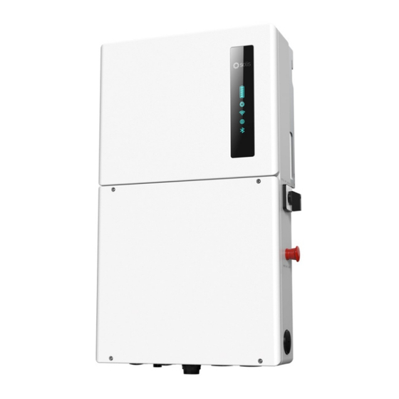
User Manual 1.1 Inverter Description The Solis S6 Hybrid series is designed for residential applications. The inverter can work with high-voltage lithium ion batteries to maximize self-consumption and provide backup power if the grid fails and there is not enough PV power to cover load demand. - Page 6 1. Introduction User Manual Mounting Bracket Hook Carrying Handle DC Disconnect Switch 1 in. Knockout for DC PV Solis Data Logger (sold separately) Figure 1.3 Right Side View Mounting Bracket Hook Carrying Handle AC Bypass Switch Rapid Shutdown Initiation Switch 1 ½...
- Page 7 1. Introduction User Manual Heat Sink for Convective Cooling 1 ½ in. Knockout for AC Grid or Backup 1 in. Knockout for DC Battery or PV Figure 1.5 Back View Figure 1.6 Top View...
-
Page 8: Inverter Wire Box And Connection Points
1. Introduction User Manual 1.2 Components Included with the Inverter If any of these items are missing, please contact your local Solis distributor or the Solis service team. Inverter Mounting Bracket x1 Stabilizing Set Screws x2 Inverter x1 1/2 inch Cable Glands x2... -
Page 9: Packaging
1. Introduction User Manual 1.4 Inverter Storage ● If the inverter is not installed immediately, please abide by the storage instructions and environmental conditions listed below. ● Use the original box to repackage the inverter, seal with adhesive tape with the desiccant inside the box. -
Page 10: Safety
2. Safety & Warning User Manual 2.1 Safety The following types of safety instructions and general information appear in this document as described below: DANGER “Danger” indicates a hazardous situation which if not avoided, will result in death or serious injury. WARNING “Warning”... - Page 11 NEC Article 690, Part II. All Solis single phase inverters feature an integrated DC disconnect switch. CAUTION Risk of electric shock, do not remove the cover. There are no serviceable parts inside, refer servicing to qualified and accredited service technicians.
-
Page 12: Notice For Use
Local waste management rules shall be observed and respected. 2.5 Protection Circuitry and Controls To meet relevant codes and standards, the Solis U.S. single phase inverter line is equipped with protective circuitry and controls. These include Arc Fault Circuit Interrupter (AFCI) and Anti-Islanding Protection. -
Page 13: Overview
User Manual 3.1 LED Indicator Lights There are five indicator lights on the the Solis S6-EH1P(3.8-11.4)K-H-US Series Inverter: Battery, Inverter, Wi-Fi, RS485 and Bluetooth. These lights indicate the working status of the inverter. The inverter creates a Bluetooth signal which is what the smart phone connects to so that the inverter interface page can be accessed. -
Page 14: Inverter Wire Box And Connection Points
Conduit for battery conductors should be connected here 3. Battery Solis data logger gets connected here - only USB versions of the loggers will work 4. Solis Logger Conduit for AC conductors to backup loads panel should be connected here 5. -
Page 15: Installation
4. Installation User Manual 4.1 Select a Location to Install the Inverter When selecting a location for the inverter, the following criteria should be considered: Exposure to direct sunlight may cause output power derating due to overheating It is recommended to avoid installing the inverter in direct sunlight. The ideal location is one where the ambient temperature does not exceed 40°C (140°F) It is also recommended to install the inverter somewhere the rain and snow will not land directly on it. - Page 16 ● Consult the technical specifications sections at the end of this manual for additional environmental condition requirements (temperature range, altitude, etc.) 4.1.3 Angle of installation ● This model of Solis inverter must be mounted vertically (90° degrees not greater or less than 90° degrees straight up).
-
Page 17: Product Handling
4. Installation User Manual 4.1.4 Avoiding direct sunlight Installation of the inverter in a location exposed to direct sunlight should to be avoided. Direct exposure to sunlight could cause: ● Power output limitation (with a resulting decreased energy production by the system). ●... -
Page 18: Mounting The Inverter
4. Installation User Manual 4.3 Mounting the Inverter ● Mount the inverter on a wall or structure capable of bearing the weight of the machine ● The inverter must be mounted upright on a vertical structure with a tilt of 90°. A tilt greater or less than 90°... - Page 19 4. Installation User Manual Length Width Depth 34 ¹⁄ (866 mm) 17 ¹⁵⁄ (455 mm) 19 ¹⁄ (485 mm) 5 ⅜ in. 21 ⅞ in. (136.5 mm) (555.5mm) 8 ⅝ in. (218.5 mm) Figure 4.6 Inverter Dimensions Figure 4.7 Inverter Bracket Dimensions Once a suitable location has been found according to 4.2 and 4.3, use figures 4.6 and 4.7 to mount the bracket to the wall.
- Page 20 4. Installation User Manual NOTE: The inverter must be mounted vertically at a 90° angle. Four fasteners must be used to ensure the bracket does not come off the wall. At least two must embed in a wall stud to bear the inverter weight. Bracket Fasteners Figure 4.8 Fix the bracket to the wall...
-
Page 21: Inverter Wiring Overview
(For more details, please refer to the on SolisCloud (Optional) Solis data logger product manual) Table 4.1 System Cable Connections Conductor, conduit, and overcurrent protection device sizing shall be done in accordance with the NEC and local electrical codes & standards. -
Page 22: External Grounding
4. Installation User Manual 4.5 External Grounding An optional external ground connection point is available on the right side of inverter. The internal ground bar is grounded to the inverter chassis. Figure 4.10 External Grounding Conductor Terminal Location To connect the grounding terminal on the heat sink, please follow the steps below: 1. -
Page 23: Pv Cable Installation
4. Installation User Manual 4.6 PV Cable Installation Danger: Before installing the PV cables, be sure that the PV array is disconnected. Use a multimeter to verify that the PV string voltages are 0V before proceed- ing.If rapid shutdown is being used, then under 30Vdc per string is safe. Please verify the following before connecting the PV strings to the inverter: Ensure the DC voltage of the PV strings will not exceed the maximum DC input voltage (600Vdc). -
Page 24: Rapid Shutdown
4. Installation User Manual 4.7 Rapid Shutdown 4.7.1 Integrated Rapid Shutdown Important Note The inverter comes (optional) with an internal rapid shutdown transmitter. This transmitter brand must match the receivers that are being installed with the PV modules. Not abiding by this will void the inverter warranty. How the inverter achieves module-level rapid shutdown: The internal transmitter generates a PLC signal when it receives AC power. - Page 25 4. Installation User Manual 4.7.2 External Rapid Shutdown If the inverter is being installed where it is inaccessible to first responders, an external rapid shutdown switch must be installed somewhere it is accessible. Steps for Installing an External Rapid Shutdown Initiation Switch 1.
-
Page 26: Battery Installation
Compatibility sheet for specifics on which battery models this inverter will support. Note: The battery fuse in the inverter wire box is replaceable. The replacement can only be done by a technician authorized by Solis. Fuse specification: 750V, 63A. Note:... -
Page 27: Ac Wiring
Table 4.4: Grid Max Output Backup Rated Backup Max Output Grid Max Input Inverter Model Current Current Output Current Current (10 sec) S6-EH1P3.8K-H-US 15.8A 23.8 23.8A 15.8A 25.4A S6-EH1P5K-H-US 20.8A 31.2A 20.8 33.3A... - Page 28 4. Installation User Manual Overcurrent protection device and service panel sizing shall be done in accordance with the NEC and local electrical codes and standards. 4.9.2 AC Bypass Switch AC Bypass Switch This failsafe switch determines the power source for the inverter backup circuit.
- Page 29 4. Installation User Manual Depending on the battery, the S6 hybrid can have anywhere from 10kWh to 60kWh of stored power to provide in backup mode or for time-of-use. It is recommended to determine how much average PV power will be available and what average power consumption is to understand how long the battery will last in the event of a grid outage.
- Page 30 4. Installation User Manual 4.9.4 Installing the AC cables DANGER: Before installing the AC cables, be sure that the OCPDs (breakers) are turned off. Use a multimeter to verify that the AC voltages are 0Vac before proceeding. Steps for installing the grid and backup AC cables 1.
-
Page 31: Inverter Communication
4. Installation User Manual 4.10 Inverter Communication 4.10.1 Communication Terminals Overview Figure 4.20 Inverter communication terminals The inverter communication terminals consist of 16 ports. From left to right, the chart below explains what they all are and are for. Acceptable Port Function Wire Size Range... - Page 32 4. Installation User Manual Note: COM1 and COM2 conduit knockouts are for ½ inch cable glands or conduit fittings. Please be sure to not run com cables in the same conduit as high voltage conductors. Doing this could cause communication issues. Steps for installing the communication wires: 1.
- Page 33 CAN-H (blue wire) Battery CAN-L (blue-white wire) CAN Port Battery CAN Port RJ 45 Connector Solis S6 Hybrid 3.8-11.4K Figure 4.22 Battery CAN Communication LG RESU Prime Battery Solis S6 Hybrid 3.8-11.4K Figure 4.23 Battery RS 485 Communication Note: Some alarm codes are being relayed from the battery. These alarms are caused by an issue with the battery itself.
- Page 34 The inverter can be remotely monitored if a Solis data logger is installed. The USB “COM” port at the bottom of the inverter can connect to various kinds of Solis data loggers which allows for remote monitoring of the system on Soliscloud platform.
-
Page 35: Commissioning
5. Commissioning User Manual 5.1 Pre-Commissioning Steps Make sure that no high voltage conductors are energized. Check all conduit and cable connection points to ensure they are tight. Verify that all system components have adequate space for ventilation. Follow each cable to ensure that they are all terminated in the proper places. E nsure that all warning signs and labels are affixed on the system equipment. - Page 36 5. Commissioning User Manual Step 4: Turn your phone Bluetooth on and then open the SolisCloud app. Go to “Me”, then tap “Tool”, then “Local Operation”, and then tap ”Connect with Bluetooth”. Tap the arrow to display nearby Bluetooth devices. Then tap BR2262e-S (note: if this device does not appear, be sure the inverter is at least getting start-up DC voltage).
- Page 37 5. Commissioning User Manual Step 5: If this is the first time the inverter has been commissioned, you will need to first go through the Quick Settings. Once this has been done, these settings can be changed later. A. Inverter Time: Set the Inverter Time and date. It may be easier to tap the slider next to “Follow Phone Time”.
- Page 38 5. Commissioning User Manual E. Work Mode: This is the energy storage operating mode. All four modes first priority is to use the available PV power to support the home loads. The different modes determine what the second priority, or use of the excess PV power, will be. Select the desired mode, then tap the slider switch to turn the mode on.
- Page 39 5. Commissioning User Manual Step 6: After the initial settings are done, you will be taken to the homepage where you will see different icons. At the bottom of the page are four submenus: Home, Info, Settings, and More. The Info page breaks down into four categories: Inverter, Battery, Grid, and Load. Inverter: inverter power production history, PV voltages and currents, inverter information (serial number, model number, and firmware version), grid code, and alarm code history...
- Page 40 The inverter commissioning process has now been completed. It is recommended to monitor the system closely over the next week to ensure that everything is working as it should. Please refer to the Solis data logger manual for assistance with registering a new plant on SolisCloud.
-
Page 41: Troubleshooting
If you are not able to resolve the alarm code using the troubleshooting steps, or if the alarm code you are seeing is not listed, please contact Solis US Technical support. Use the Bluetooth tool, go to the Info page and then to the Inverter tab. Scroll down and tap Alarm History and then screen shot or write down the alarms as well as the dates and times the alarms were recorded. - Page 42 6. Troubleshooting User Manual Alarm Message Failure description Solution 1. Check if there is an arc in the PV ARC-FAULT ARC detected in DC circuit connection and restart inverter. AFCI Check FAULT AFCI module self check fault 1. Restart inverter or contact installer. DCinj-FAULT High DC injection current 1.
- Page 43 6. Troubleshooting User Manual Alarm Message Failure description Solution Over DC voltage OV-DC01/02/03/04 1. Reduce the module number in series. 1. Restart inverter. 2. Identify and remove the string of the DC input overcurrent OV-DCA-I faulted MPPT. 3. Change power board. 1.
- Page 44 Solis after-sales service +1(866)438-8408 or email usservice@solisinverters.com If you have any technical problems with the hybrid system, please contact Solis after-sales service. We recommend gathering the following information before making contact in order to get a quicker resolution.
-
Page 45: Specifications
7. Specifications User Manual Technical Data S6-EH1P3.8K-H-US S6-EH1P5K-H-US Input DC (PV side) Recommended max. PV power 6,080W 8,000W Max. input voltage 600V Rated voltage 380V Start-up voltage MPPT voltage range 80-550V Full load MPPT voltage range 140-450V Max. input current per string Max. - Page 46 7. Specifications User Manual Technical Data S6-EH1P3.8K-H-US S6-EH1P5K-H-US AC Output (Backup and Off-grid) Rated output power 3.8kW Max. apparent output power 6.1 kVA, 10 sec 8 kVA, 10 sec Back-up switch time <10 ms Phase Power 240V Split-Phase Rated output voltage(L1-L2)/(L1/L2-N)
- Page 47 7. Specifications User Manual Technical Data S6-EH1P3.8K-H-US S6-EH1P5K-H-US General data Dimensions(H/W/D) 25.5*19.2*9 in (647*488*228.5 mm) Weight 44.1 Ibs (20 kg) Topology Transformerless Operation temperature range -25~+60 ℃/-31~+140 ℉ Ingress protection NEMA 4X(IP66) <30 dB (A) Noise emission (Typical) Cooling method Natural convection Max.
- Page 48 7. Specifications User Manual Technical Data S6-EH1P7.6K-H-US S6-EH1P8K-H-US Input DC (PV side) Recommended max. PV power 12160W 12800W Max. input voltage 600V Rated voltage 380V Start-up voltage MPPT voltage range 80-550V Full load MPPT voltage range 175-450V 185-450V Max. input current per string Max.
- Page 49 7. Specifications User Manual Technical Data S6-EH1P7.6K-H-L-US S6-EH1P8K-H-US AC Output (Backup and Off-grid) Rated output power 7.6kW Max. apparent output power 12.2 kVA, 10 sec 12.8 kVA, 10 sec Back-up switch time <10 ms Phase Power 240V Split-Phase Rated output voltage(L1-L2)/(L1/L2-N) 240 V/120 V AC output voltage range 204-276 V...
- Page 50 7. Specifications User Manual Technical Data S6-EH1P7.6K-H-L-US S6-EH1P8K-H-US General data Dimensions(H/W/D) 26.6*21.9*9.4 in (676*555*238.5 mm) Weight 81.1 Ibs (36.8 kg) Topology Transformerless Operation temperature range -25~+60 ℃/-31~+140 ℉ Ingress protection NEMA 4X(IP66) <30 dB (A) Noise emission (Typical) Cooling method Natural convection Max.
- Page 51 7. Specifications User Manual Technical Data S6-EH1P10K-H-US S6-EH1P11.4K-H-US Input DC (PV side) Recommended max. PV power 16,000W 18,240W Max. input voltage 600V Rated voltage 380V Start-up voltage MPPT voltage range 80-550V Full load MPPT voltage range 230-450V 245-450V Max. input current per string Max.
- Page 52 7. Specifications User Manual Technical Data S6-EH1P10K-H-US S6-EH1P11.4K-H-US AC Output (Backup and Off-grid) Rated output power 10kW 11.4kW Max. apparent output power 16 kVA, 10 sec 18.2 kVA, 10 sec Back-up switch time <10 ms Phase Power 240V Split-Phase Rated AC output voltage 240 V/120 V AC output voltage range 204-276 V...
- Page 53 7. Specifications User Manual Technical Data S6-EH1P10K-H-US S6-EH1P11.4K-H-US General data Dimensions(H/W/D) 26.6*21.9*9.4 in (676*555*238.5 mm) Weight 81.1 Ibs (38.6 kg) Topology Transformerless Operation temperature range -25~+60 ℃/-31~+140 ℉ Ingress protection NEMA 4X (Ip66) <30 dB (A) Noise emission (Typical) Cooling method Natural convection Max.operation altitude 13,120 ft (4000 m)
-
Page 54: Appendix
8. Appendix User Manual 8.1 Single Line Diagram 1: One hybrid inverter... - Page 55 8. Appendix User Manual...
- Page 56 A5: Yes, as long as the inverter has a Solis data logger installed and is registered on SolisCloud. The Solis Support team can do remote settings changes and firmware updates. Q6: What is the Solis Power Hub mentioned in the video and will that launch at the same time as the new S6 hybrid inverter? A6: The Solis Power Hub is a microgrid interconnection device (MID) that will be an optional accessory only required if you are looking to get whole home backup with the S6 inverter.
- Page 57 Q9: Will the S6 hybrid work with a generator? A9: Yes, but you will need to install a Solis Power Hub as well. The inverter does not have a generator connection point, but it can work alongside a generator if the Power Hub is also installed since it does have a generator input.
- Page 58 8. Appendix User Manual 8.3 Temperature Derating Curve (120.2°F) (131°F) (140°F) 8.4 Inverter Internal Topology Overview...
- Page 59 MEX, S6-EH1P7.6K-H-L-MEX, S6-EH1P8K-H-MEX, S6-EH1P10K-H-MEX and S6-EH1P11.4K-H-MEX, permanently connected. Bi-directional Transformerless Grid Support Utility Interactive Power Conversion Equipment, S6-EH1P(3.8- 11.4)K-H-US series, include Models S6-EH1P3.8K-H-US, S6-EH1P5K-H-US, S6-EH1P6K-H-US, S6- EH1P7.6K-H-S-US, S6-EH1P7.6K-H-L-US, S6-EH1P8K-H-US, S6-EH1P10K-H-US and S6-EH1P11.4K-H-US, permanently connected. For details related to rating, size, configuration, etc., reference should be made to the CSA Certification Record, Certificate of Compliance, Annex A, or the Descriptive Report.
- Page 60 8. Appendix User Manual Certificate: 80127112 Master Contract: 273488 Project: 80127113 Date Issued: 2023-01-13 APPLICABLE REQUIREMENTS CSA-C22.2 No.107.1-16 Power Conversion Equipment *UL Std No. 1741 Inverters, Converters, Controllers and Interconnection System Equipment for Use With Distributed Energy Resources (Third Edition, Dated September 28, 2021) **UL 1699B Photovoltaic (PV) DC Arc-Fault Circuit Protection (First Edition, Revision Dated August 22, 2018)
- Page 61 Description 80127113 2023-01-13 Updated report 80127112 to add S6-EH1P(3.8-11.4)K-H-US series inverter, include models S6-EH1P3.8K-H-US, S6-EH1P5K-H-US, S6-EH1P6K-H- US, S6-EH1P7.6K-H-S-US, S6-EH1P7.6K-H-L-US, S6-EH1P8K-H-US, S6- EH1P10K-H-US, S6-EH1P11.4K-H-US and evaluate the Grid support function to comply with UL 1741 Supplement SA8-SA18 with the SRDs of California Electric Rule 21 and UL 1741 Supplement SB according to IEEE 1547.1-2020 with SRDS IEEE 1547-2018 and IEEE 1547a-2020.
- Page 62 Ginlong Technologies Co., Ltd. No. 188 Jinkai Road, Binhai Industrial Park, Xiangshan, Ningbo, Zhejiang, 315712, P.R.China. Tel: +86 (0)574 6578 1806 Fax: +86 (0)574 6578 1606 Please adhere to the actual products in case of any discrepancies in this user manual. If you encounter any problem on the inverter, please find out the inverter S/N and contact us, we will try to respond to your question ASAP.
Need help?
Do you have a question about the S6-EH1P3.8K-H-US and is the answer not in the manual?
Questions and answers