Epiq Solutions Sidekiq X4 Hardware User Manual
Rf transceiver
Hide thumbs
Also See for Sidekiq X4:
- Integration manual (28 pages) ,
- Getting started manual (15 pages) ,
- Development manual (29 pages)

Related Manuals for Epiq Solutions Sidekiq X4


Summary of Contents for Epiq Solutions Sidekiq X4
- Page 1 Sidekiq™ X4 RF Transceiver • High Performance HARDWARE USER MANUAL V1.4 - APRIL 07, 2022...
- Page 2 Sidekiq™ X4 | Hardware User Manual CHANGELOG Revision Date Description Author 2018-10-06 Pre-release draft, initial version Barry L 2018-10-13 Update diagrams, pictures Barry L 2019-01-03 Updated section 7, figure 4, section 8 Barry L 2019-04-25 Updated section 9, FMC pinout Barry L Updated sections 7.1, 8, 8.7, 10.3, figure 4Added figure 8, table 4, table 5, &...
- Page 3 Epiq Solutions is disclosing this document (“Documentation”) as a general guideline for development. Epiq Solutions expressly disclaims any liability arising out of your use of the Documentation. Epiq Solutions reserves the right, at its sole discretion, to change the Documentation without notice at any time. Epiq Solutions assumes no obligation to correct any errors contained in the Documentation, or to advise you of any corrections or updates.
-
Page 4: Table Of Contents
..................Sidekiq X4 Mechanical Outline... - Page 5 ..................42 Accessing JTAG on the Sidekiq X4 Thunderbolt 3 Platform .
-
Page 6: Introduction
RF platform development cycle. Sidekiq X4 can interface to any FMC HPC host system, where an FPGA and additional follow on processing would be executed. Epiq Solutions provides an FPGA reference design as well as software drivers, libraries, and test applications to demonstrate the usage of Sidekiq X4 interfaced to a COTS FMC host platform with a PCIe interface to a host computing system. -
Page 7: Legal Considerations
Legal Considerations LEGAL CONSIDERATIONS The Sidekiq X4 is distributed all over the world. Each country has its own laws governing reception and transmission of radio frequencies. Each user of Sidekiq X4 and associated software is solely responsible for insuring that it is used in a manner consistent with the laws of the jurisdiction in which it is used. -
Page 8: Proper Care And Handling
Each Sidekiq X4 card is fully tested by Epiq Solutions before shipment, and is guaranteed functional at the time it is received by the customer, and ONLY AT THAT TIME. Improper use of the Sidekiq X4 card can cause it to become non-functional. In particular, a list of actions that may cause damage to... -
Page 9: References
Sidekiq™ X4 | Hardware User Manual References REFERENCES 1. Sidekiq X4 Product Page https://epiqsolutions.com/modules/sidekiq-x4 2. Epiq Solutions Support Page https://www.epiqsolutions.com/support 3. VITA website http://www.vita.com 4. Analog Devices' ADRV9009 Wideband Transceiver Product Page http://www.analog.com/en/products/adrv9009.html 5. Hi Tech Global's Product Page for the HTG-K800 FPGA PCIe Carrier Card http://www.hitechglobal.com/Boards/Kintex-UltraScale.htm... -
Page 10: Terms And Definitions
Platform Development Kit Pulse Per Second Radio Frequency Receive Software Development Kit Software Defined Radio Sub-Miniature push-on RF connector SSMC A smaller version of the SubMiniature type C RF connector TCVCXO Temperature Compensated Voltage Controlled Crystal Oscillator Epiq Solutions Proprietary Page 10... - Page 11 Transmit Universal Serial Bus Voltage Input High (the minimum logic level high voltage) The standards body governing a variety of electro-mechanical specifications for computing systems (see [3] for VITA details). Table 1: Terms and Definitions Epiq Solutions Proprietary Page 11...
-
Page 12: Hardware Overview
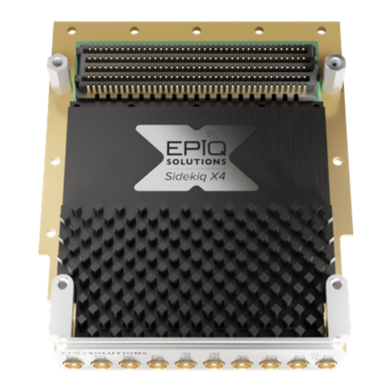
Sidekiq X4 is a high performance multi-channel RF transceiver card providing a complete “antenna- to-bits” solution in a VITA 57.1 FPGA mezzanine card (FMC) form factor. Sidekiq X4 leverages two Analog Devices' ADRV9009 wideband transceiver RFICs [4] to provide the core functionality of the card. - Page 13 Sidekiq™ X4 | Hardware User Manual Hardware Overview Figure 1: Sidekiq X4 Epiq Solutions Proprietary Page 13...
- Page 14 Figure 2: Block diagram of Sidekiq X4 Note: Sidekiq X4 is based on two TDD RFICs which means that Rx and Tx cannot be streaming at the same time when using just one RFIC. You can however, stream TX for an A* handle (RFIC A) simultaneously to receiving on a B* handle (RFIC B).
-
Page 15: Hardware Specification
+27 dBm damage) RF full scale input (at max gain) -20 dBm (frequency dependent) Automatically selected when tuning the RF receiver; see Figure 3 for passband RF Pre-Select Filter Passbands details Table 2: rx specification Epiq Solutions Proprietary Page 15... -
Page 16: Rf Transmitter Specification (Tx1, Tx2)
D/A Converter Sample Width 14 bits Typical I/Q Balance > 60 dB D/A JESD204b Lane Rate Up to 12.288 Gbps # of JESD204b Lanes Utilized 1 or 2 lanes (sample rate dependent) Table 3: tx specification Epiq Solutions Proprietary Page 16... -
Page 17: Clock/Synchronization Specification
2.7 oz -55 deg C to +125 deg C (+/- 2 deg C resolution)(P/N: Texas Instruments Temperature Sensor TMP100NA/250) FMC (12P0V) +12V FMC (P3V3) +3.3V FMC Vadj Support +1.8V / +2.5V Table 5: hardware specification Epiq Solutions Proprietary Page 17... - Page 18 1680 to 2580 MHz > 1700 and <= 2700 MHz 2500 to 3880 MHz > 2700 and <= 3600 MHz 3800 to 6000 MHz > 3600 and <= 6000 MHz Table 6: Rx pre-select filter bands Epiq Solutions Proprietary Page 18...
-
Page 19: Hardware Interfaces
Hardware Interfaces HARDWARE INTERFACES Sidekiq X4 provides is a standard VITA 57.1 compliant FMC card, and thus has a specific set of externally accessible hardware interfaces that are available to a user when the card is integrated into a system. Each of these hardware interfaces are enumerated in Figure 4, and are defined below. -
Page 20: J2 (Rxa1)
API provides a function call to disable on the on-board 40 MHz reference and lock on to this external 10 or 40 MHz reference input. Revision C of Sidekiq X4 can also use this port (configured via libsidekiq) as either the REF Input (default) or the input for an externally-provided DEV_CLK which is required for multi-card synchronization. -
Page 21: J5 (Txb2)
0.85V and 5V, dependent on Vadj (+1.8V / +2.5V). This PPS signal is used by the Sidekiq X4 FPGA reference design to latch the digital timestamp of when the PPS edge occurs in the FPGA, and can then be queried by the libsidekiq software API. -
Page 22: Rf Shield & Heatsink
TBD LFM is required to ensure that the heat generated by the card is adequately dissipated. VITA 57.1 HPC CONNECTOR The VITA 57.1 HPC connector is the primary electrical interface for connecting Sidekiq X4 to a host system. The complete pin mapping for signals accessible through this HPC interface on Sidekiq X4 is defined in the FMC High Pin Count (HPC) Section. -
Page 23: Fmc Pin Map
FMC specification, and more importantly, the Sidekiq X4 FPGA reference design delivered with the Sidekiq X4 PDK. Epiq Solutions provides support for Sidekiq X4 when used in conjunction with the Sidekiq X4 FPGA reference design and associated libsidekiq software library. - Page 24 VADJ input LA17_N_CC GP_INTERRUPT_B interrupt from RFIC B VADJ input LA23_P LED_BLU enables blue LED VADJ input NC on Rev B, determines the functionality of LA23_N FMC_EXT_DEV_CLK_SEL VADJ input (J5) EXT_10M input on Rev C Epiq Solutions Proprietary Page 24...
- Page 25 JESD RX channel sync for RFIC A LVDS input LA12_P TX2_ENABLE_A enables TX2 for RFIC A VADJ input LA12_N RX2_ENABLE_A enables RX2 for RFIC A VADJ input LA16_P SYNCIN1_B.D_P JESD RX channel sync for RFIC B LVDS input Epiq Solutions Proprietary Page 25...
- Page 26 JESD TX channel data sync for RFIC A LVDS output LA02_N SYNCOUT0_A.D_N JESD TX channel data sync for RFIC A LVDS output LA04_P FMC_SPI_CS_A SPI chip select for RFIC A VADJ input LA04_N FMC_SPI_CS_9528 SPI chip select for clock IC VADJ input Epiq Solutions Proprietary Page 26...
-
Page 27: Fmc High Pin Count (Hpc) Section
VADJ VADJ adjustable power supply from host to mezzanine DC in 2.5V Table 7: FMC Low Pin Count Pinout FMC HIGH PIN COUNT (HPC) SECTION Sidekiq X4 Net FMC Name Description Logic/Standard Type Comments name JESD output lane for RX... - Page 28 JESD input lane for TX SERDIN2 on RFIC CML (current mode DP5_C2M_P DP5_C2M.DP input logic) JESD input lane for TX SERDIN2 on RFIC CML (current mode DP5_C2M_N DP5_C2M.DN input logic) RES1 RESERVED CML (current mode DP9_M2C_P output logic) Epiq Solutions Proprietary Page 28...
- Page 29 RFIC A logic) RES0 RESERVED input/ HA01_P_CC GPIOA11 GPIO bus to RFIC A VADJ output input/ HA01_N_CC GPIOB11 GPIO bus to RFIC B VADJ output input/ HA05_P GPIOA15 GPIO bus to RFIC A VADJ output Epiq Solutions Proprietary Page 29...
- Page 30 GPIO bus to RFIC A VADJ output input/ HA00_N_CC GPIOB10 GPIO bus to RFIC B VADJ output input/ HA04_P GPIOA14 GPIO bus to RFIC A VADJ output input/ HA04_N GPIOB14 GPIO bus to RFIC B VADJ output Epiq Solutions Proprietary Page 30...
- Page 31 GPIO bus to RFIC A VADJ output input/ HA03_N GPIOB13 GPIO bus to RFIC B VADJ output input/ HA07_P GPIOA17 GPIO bus to RFIC A VADJ output input/ HA07_N GPIOB17 GPIO bus to RFIC B VADJ output Epiq Solutions Proprietary Page 31...
- Page 32 GPIO bus to RFIC A VADJ output input/ HA02_N GPIOB12 GPIO bus to RFIC B VADJ output input/ HA06_P GPIOA16 GPIO bus to RFIC A VADJ output input/ HA06_N GPIOB16 GPIO bus to RFIC B VADJ output HA10_P HA10_N Epiq Solutions Proprietary Page 32...
- Page 33 HA23_N HB00_P_CC HB00_N_CC HB06_P_CC HB06_N_CC HB10_P HB10_N HB14_P HB14_N HB17_P_CC HB17_N_CC connected to VADJ through 1.8V to logic level on band B for VIO_B_M2C VDD_INTERFACE jumper 2.5V FPGA Table 8: FMC High Pin Count Pinout Epiq Solutions Proprietary Page 33...
-
Page 34: Basic Usage In A Host System
BASIC USAGE IN A HOST SYSTEM HOST SYSTEM COMPATIBILITY Sidekiq X4 is expected to be deployed into a host system that adheres to a general architecture in order to utilize the core FPGA reference design and associated libsidekiq software API. This general architecture is shown in Figure 5 below. -
Page 35: Operating System Compatibility
Basic Usage in a Host System In an alternate deployment scenario, Sidekiq X4 can be interfaced to a 3U VPX carrier card that hosts an integrated FPGA + CPU in a single chip, such as the Xilinx Zynq Ultrascale+ SoC. In this scenario, both the FPGA fabric required to execute the Sidekiq X4 FPGA reference design and the multi-core ARM CPU running the libsidekiq software library are located on a single device (i.e., the... - Page 36 Sidekiq™ X4 | Hardware User Manual Basic Usage in a Host System The power consumption of Sidekiq X4 card is largely dependent on the number of RF channels being utilized and the sample rate at which those channels are operating. The power consumption of the card will vary between ~7W and ~11W based on this configuration.
-
Page 37: Thermal Dissipation
For a standard convection cooled deployment, the required air flow over the heatsink on the card is TBD LFM. Sidekiq X4 uses components that are rated for operation to +85 deg C, and thus the end user must ensure that the temperature reported by the on-board temperature sensor does not exceed +85 deg C. -
Page 38: Jtag Access On Sidekiq
Sidekiq™ X4 | Hardware User Manual Basic Usage in a Host System Figure 8: Sidekiq X4 Top and Bottom Sides The thermal gap pad material used on the X4 RFICs is Bergquist Gap Pad P/N: GPVOUS- 0.040-00 The thermal pads are 0.50" x 0.50" x 0.060" thick and 0.040" thick respectively and are compressed around 50%. -
Page 39: Sidekiq X4 Mechanical Outline
Sidekiq X4 Mechanical Outline SIDEKIQ X4 MECHANICAL OUTLINE A dimensioned mechanical drawing of Sidekiq X4 in convection cooled form is shown in Figure 9. In addition, a 3D model (in STP format) is also available. Please contact Epiq Solutions for this model. - Page 40 Sidekiq X4 + HTG-K800 PCIe card installed into the Thunderbolt 3 chassis and connected to a host laptop is shown in Figure 9. Figure 10: Sidekiq X4 & HTG-K800 FPGA host board installed into a Thunderbolt 3 chassis, interfaced to a laptop via a Thunderbolt 3 cable...
- Page 41 Thunderbolt 3 platform that ships with the PDK: Step 1. With the Sidekiq X4 Thunderbolt 3 platform powered on first (using the provided DC power brick for the Thunderbolt 3 chassis), connect the TB3 chassis to the laptop with the provided TB3 cable and power on the laptop last.
- Page 42 ACCESSING JTAG ON THE SIDEKIQ X4 THUNDERBOLT 3 PLATFORM For customers adding their own custom FPGA blocks in the “user_app” area of the Sidekiq X4 reference design, it can often be useful to access JTAG to monitor signals in the FPGA through Xilinx's Chipscope software running on a separate PC.
- Page 43 Sidekiq™ X4 | Hardware User Manual Sidekiq X4 Thunderbolt 3 Platform Figure 11: JTAG port access on the Sidekiq X4 Thunderbolt 3 platform Once the JTAG cable is installed, the Thunderbolt 3 chassis cover can be carefully replaced, as shown in Figure 11, with the JTAG cable coming through the front panel of the unit. This ensures that the airflow from the internal fans is properly ducted over the critical components including Sidekiq X4.
- Page 44 Sidekiq™ X4 | Hardware User Manual Sidekiq X4 Thunderbolt 3 Platform Figure 12: Thunderbolt 3 chassis closed up with Xilinx JTAG interface installed With the Thunderbolt 3 chassis reassembled, the user can resume normal usage of the system. Epiq Solutions Proprietary...
- Page 45 Sidekiq™ X4 | Hardware User Manual Appendix A – Sidekiq X4 Statement of Volatility APPENDIX A – SIDEKIQ X4 STATEMENT OF VOLATILITY Model Sidekiq X4 Part Number ES024-xxx Manufacturer Epiq Solutions 3740 Industrial Avenue Address Rolling Meadows, IL 60008 Table 11: Model, Part Number, and Manufacturer Info...
- Page 46 Appendix B – Failure Rate & MTBF APPENDIX B – FAILURE RATE & MTBF Listed below is the Failure Rate and MTBF for the ES024-211-01-B Sidekiq X4 Assembly. The Calculations are derived from Relyence Reliability Software and based off a fixed/ground/controlled operating environment with an ambient temperature of 25°C.
Need help?
Do you have a question about the Sidekiq X4 and is the answer not in the manual?
Questions and answers