GE Zoneline 6100 Series Technical Service Manual
Hide thumbs
Also See for Zoneline 6100 Series:
- Owner's manual and installation instructions (72 pages) ,
- Data manual (60 pages)

Subscribe to Our Youtube Channel
Related Manuals for GE Zoneline 6100 Series


Summary of Contents for GE Zoneline 6100 Series
- Page 1 GE Appliances Technical Service Guide September 2010 Zoneline Air Conditioners 6100 Series 31-9202 GE Appliances General Electric Company Louisville, Kentucky 40225...
- Page 2 If grounding wires, screws, straps, clips, nuts, or washers used to complete a path to ground are removed for service, they must be returned to their original position and properly fastened. GE Appliances Technical Service Guide Copyright © 2010 All rights reserved. This service guide may not be reproduced in whole or in part in any form without written permission from the General Electric Company.
-
Page 3: Table Of Contents
Sizing Guidelines ................................14 Specifi cations ..................................7 Tangential Blower ................................49 Technical Data ...................................11 Thermistors ..................................45 Troubleshooting ................................58 User Controls ..................................24 Vent Door and Cable ...............................38 Warranty ....................................63 Zoneline 6100 Series ............................... 5 Zoneline Features and Specifi cations ........................6 – 3 –... -
Page 4: Nomenclature
Nomenclature Model Number AZ 61 H 07 D A B M 1 Engineering Zoneline Revision Packaged Terminal Chassis M = MEI Compressor W = Rechi Compressor Chassis Series Heat Pump Special Features B = Standard Unit Type C = Corrosion H = Cooling w/Heat Pump and D = Internal Condensate Removal (ICR) Electric Resistance Heat... -
Page 5: Zoneline 6100 Series
Zoneline 6100 Series 208/230-Volt 265-Volt Standard AZ61 H07 DAB AZ61 H07 EAB AZ61 H09 DAB AZ61 H09 EAB AZ61 H12 DAB AZ61 H12 EAB AZ61 H15 DAB AZ61 H15 EAB AZ61 H07 DAD AZ61 H07 EAD AZ61 H09 DAD AZ61 H09 EAD... -
Page 6: Zoneline Features And Specifi Cations
Zoneline Features and Specifi cations Features Refrigerant Type R-410A Universal heater ― UPC* Standard Highly featured microcomputer controls Standard Tactile touch pad controls with LED Standard Automatic power recovery Standard Solid-state thermostat Standard Cool and Heat only settings Hi/Low/Auto Sleep function Standard 7-step electronic temperature limiting Standard... -
Page 7: Specifi Cations
Specifi cations Deluxe series – heat pump units** 6100 series units 230/208V Models AZ61H07D AZ61H09D AZ61H12D AZ61H15D Capacity Cooling BTUH 7,200/7,000 9,400/9,200 11,800/11,600 14,800/14,600 EER (BTU/Watt) 13.2/13.2 12.7/12.7 12.1/12.1 11.2/11.2 Dehumidification Pts/Hr Features Refrigerant type R-410A R-410A R-410A R-410A CFM, indoor fan high CFM, indoor fan low Vent CFM (full open/partial open) 50/40... -
Page 8: Features And Benefi Ts
Industry specifi cation is 19 CFM of air infi ltration. Reverse Cycle Heat Pump Defrost System Heater Sizes to Meet Room Requirements This feature is standard on all Zoneline 6100 Series. It enables the heat pump to operate at lower All units are equipped with a universal heater. The... - Page 9 The rotary compressor provides smoother operation not provided by the Zoneline. Transfer fans and their for quiet, dependable service. GE has used rotary controlling relays are fi eld-supplied. compressors since 1961.
- Page 10 Nomenclature room has an exhaust fan. • An open vent door brings unconditioned outdoor Zoneline 6100 Series units with ICR are not available air into the room, increasing heating and cooling with corrosion protection and should not be costs. installed in seacoast or corrosive environments.
-
Page 11: Technical Data
Technical Data DISCONNECT POWER BEFORE SERVICING IMPORTANT SAFETY NOTICE IMPORTANT - RECONNECT ALL GROUNDING DEVICES This information is intended for use by individuals possessing adequate backgrounds of electrical, electronic and mechanical All parts of this appliance capable of conducting electrical current are grounded. - Page 12 6100 Series Running Current Cooling - With unit in case and room front installed, operated for 10 minutes on HI-COOL. Running Current Heating - With unit in case and room front installed, operated for 10 minutes on HI-HEAT. Temperature Differential Cooling - Unit must operate for 1 hour with thermostat at coldest setting prior to measuring air temperatures.
- Page 13 15000 BTU Sealed System MODEL COMPRESSOR REFRIGERANT R410A CAPILLARY LENGTH (PC) AZ61H07D 21.0 oz. .106” .047” 15.75” (2) AZ61H07E .106” .051” 31.50” (1) .106” .051” 15.75” (1) AZ61H09D RECHI 31.5 .106” .047” 15.75” (2) AZ61H09E .106” .051” 5.91” (1) .106” .051”...
-
Page 14: Application And Sizing
Application and Sizing Oversizing Sizing Guidelines If an air conditioner is oversized (cooling capacity is The following guidelines will aid in determining the greater than required for the specifi c application), proper size unit for the space (room) allowed. These the unit will typically cool the space down to the are intended only as a guide, in order to assist in desired temperature (thermostat set point) too... - Page 15 Cooling Capacity Floor Area Table Using the charts on this page, follow the 10 ' 1 4' 18 ' guidelines listed below: 10 ' 80 140 180 12 ' 96 168 216 1. Use the to determine the Floor Area Table 14 ' 112 140 196 252 square footage of the area being cooled.
-
Page 16: Power Connection
Permanent, or direct-wired, installation of a Power Connection 230/208-volt unit requires a junction box kit, RAK4002A, that attaches to the chassis to form 230/208-Volt Line Cord Connected Units an enclosed junction box. The short sub-base line Line cord kits consist of a self-aligning nine- cord may not be used without the sub-base. - Page 17 265- or 277-Volt Unit Installation ― Permanently 265-Volt ― Direct Connection Kits Connected Units Note: The 265-volt power connection kit must be National Electric Code (Article 440 Section G) ordered separately. All wiring must conform to local requires permanent connection for units connected electrical regulations and codes.
-
Page 18: Receptacles/Sub-Bases
Receptacles/Sub-Bases Tandem Perpendicular Large tandem 265V 15 Amp 265V 20 Amp 265V 30 Amp 230/208V 15 Amp 230/208V 20 Amp 230/208V 30 Amp NEMA7-15R NEMA7-20R; NEMA7-30R; NEMA6-15R NEMA6-20R NEMA6-30R receptacle used receptacle used On 265V sub-base On 265V sub-base GE0720-3 GE073 Sub-Bases RAK204U... -
Page 19: Power Connection Kits
The following diagrams illustrate the heating Power Connection Kits capacity of 230/208 volt and 265-volt units when they are connected to 15-, 20-, or 30-amp branch The 9-pin plug on the power connection kit is not circuits. designed to be used as a disconnect device. If the power connector kit is a line cord type, remove its Power Connector Plug 15-AMP - 230/208 VAC, plug from the wall receptacle. - Page 20 Power Connector Plug 20-AMP - 230/208 VAC, Power Connector Plug 30-AMP – 230/208 VAC, 3.30/3.20 KW Heat (RAK3203A) 4.70/4.53 KW Heat (RAK3303A) The L1 side of the line is connected to terminal #3, The L1 side of the line is connected to terminal #3, and L2 is connected to terminal #7.
- Page 21 Power Connector Plug 15-Amp - 265 VAC, Power Connector Plug 20-Amp – 265 VAC, 2.4 KW Heat (RAK5172) 3.4 KW Heat (RAK5202) The L1 side of the line is connected to terminal #3, The L1 side of the line is connected to terminal #3, and L2 is connected to terminal #8.
- Page 22 Power Connector Plug 30-Amp - 265 VAC, Heater Circuit Schematic 30-Amp - 265 VAC, 4.8 KW Heat (RAK5302) 4.8 KW Heat (RAK5302) The L1 side of the line is connected to terminal #3, When the relay contacts close, the circuits to the and L2 is connected to terminal #8.
-
Page 23: Airfl Ow
Airfl ow Proper Outdoor Coil Airfl ow When properly installed in the correct wall case, the rubber seals on the inside of the outdoor grille should fi t tightly against the metal brackets on the outdoor coil. This will prevent condenser hot exhaust air from being recirculated through the coil, and will allow fresh outdoor air to enter from each of the rear sides of the outdoor grille. -
Page 24: Control Features
Control Features User Controls TEMP CONTROL FAN, MODE & SLEEP OPERATION Controls Temp Control Fan, Mode and Operation Control The temp control is used to maintain the room FAN—Sets the fan operation for HIGH, temperature. The compressor will cycle on LOW or AUTO speed. -
Page 25: Central Desk Control
There are a wide variety of devices available, each Remote Thermostat with its own benefi ts and constraints. While GE does not offer components that are external to the The unit can be controlled by an externally unit for a CDC system, GE Zonelines are compatible mounted, remote thermostat. - Page 26 Important CDC Comments (All Series Applicable) 3. A 24-volt transformer is contained in the Zoneline. No external voltage may be applied to 1. When the switching device closes the circuit of the unit through the CDC terminals. (Voltage on the CDC conductors, unit operation stops. the CDC conductors is 24 volts AC.) 2.
-
Page 27: Auxiliary Controls
Auxiliary Controls Auxiliary Set Button Auxiliary Controls—Aux Set Button The auxiliary set controls are located behind the room cabinet, below the control panel. Access Cover Remove the room cabinet. See the To Remove the Room Cabinet section. The owner is responsible for ensuring the auxiliary controls are set to the desired function. - Page 28 Freeze Sentinel/Heat Sentinel MODE 3 In the default setting for Mode 3, Heat Sentinel is off, Freeze HIGH COOL Sentinel is on. Press MODE until a 3 appears in the first digit of the display for AUTO HEAT Freeze Sentinel mode. The COOL LED light on the main control Freeze Sentinel OFF will be on.
- Page 29 Duct Mode MODE 7 The default setting for Mode 7 is OFF. For Model AZ6100, press MODE to continue setting other functions. Pressing MODE on Model AZ4100 will This setting is used when the unit is installed using a return you to AUX SET mode and an “AU” will appear in duct adapter kit.
- Page 30 All-Electric Heat (AZ6100 only) MODE 8 The default setting for Mode 8 is OFF. Press AUX SET to confirm your selection and exit AUX SET mode, or press MODE to continue setting other functions. This electric heat option functions only on the 6100 model.
- Page 31 External Fan (Obtained locally) When connected, an auxiliary or external fan can be controlled with the indoor fan motor on the Zoneline. Connections provide 24 V AC to energize a remote relay, turning on the external fan. Central Desk Control When connected, the unit can be turned ON or OFF with a switch located at the Central Control Panel.
-
Page 32: Remote Thermostat Control
Compatibility of other thermostats considered for the unit at a location remote from the unit itself use with the GE Zoneline is the responsibility of the may be desired. A unit mounted high in the wall or customer. The control voltage on the remote control over a door, where the unit-mounted controls are conductors is 24 volts AC. -
Page 33: Component Locator Views
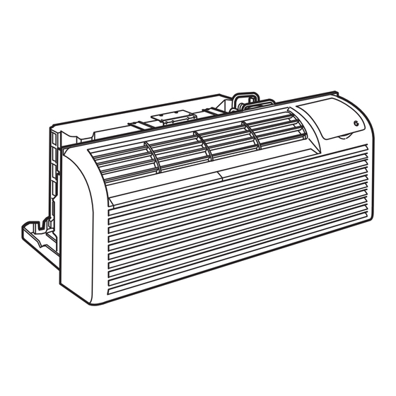
Component Locator Views Front View Control Panel Power Supply Housing Indoor Coil Power Cord Connector Room Air Thermistor Compressor Outdoor Fan Motor Vent Door Reversing Valve Indoor Fan Motor Heater Assembly Outdoor Coil Outdoor Coil Thermistor Outdoor Air Thermistor – 33 –... -
Page 34: Circuit Boards Connector Locator Views
Circuit Boards Connector Locator Views Main Board and Operation Board CN11 BCN301 BCN9 BCN302 BCN7 CN1 - Room Air, Indoor Coil, Outdoor Coil, and Outdoor Air Thermistors CN4 - BCN101 on Drive Board CN5 - BCN108 on Drive Board CN6 - BCN109 on Drive Board CN11 -Transformer, 24 VAC Note: Main board connections BCN7 and BCN9 and operation board connections BCN301 and BCN302 are permanently attached. - Page 35 Drive Board CN102 - Outdoor Fan CN103 - Indoor Fan CN104 - Transformer CN105 - Reversing Valve CN110 - Heater Power Check Circuit CN102 CN112 - Triac BCN101 CN201 - ICR Pump RY101 - Compressor RY102 - Heater Circuit (1.4 and 2.4 KW Heaters) RY108 - Reversing Valve CN103 RY110 - Heater Circuit (1 KW Heater)
- Page 36 To replace FU106 in-line fuse assembly: 3. Insert a small jewelers, fl at blade screwdriver into the fuse link section of the disconnected 1. Disconnect the in-line fuse from RY102. 3-pin wire connector. 2. Disconnect the 3-pin wire harness. 3-Pin Wire Harness RY102 FU106 Note: 230 VAC drive board shown.
-
Page 37: Components
Components To adjust air direction, remove the room cabinet Room Cabinet (grille). Remove the 7 louver screws that hold the louvers in place. Flip the louver section 180°. The room cabinet houses the reversible discharge Replace the screws and the room cabinet. louvers and the air fi... -
Page 38: Control Assembly
Vent Door and Cable Control Assembly The vent door is manually operated by a vent The user controls are located behind a door in the control, which is located at the upper left side of the top-right of the room cabinet. The room cabinet unit behind the front cabinet. -
Page 39: Control Box Components
3. Turn the control panel over and remove the 5 Control Box Components Phillips-head screws that attach the main board to the inside of the control panel. The control box houses the compressor run capacitor, transformer, main power connector, terminal board, and drive board. Control Box Component View Terminal Board 4. - Page 40 To access the control box components: Wire Terminals 1. Remove the room cabinet. (See Most of the electrical components in the unit share Room Cabinet.) wire terminals that use a small clip that holds the 2. Remove the 2 Phillips-head screws that attach wire fi...
- Page 41 Note: When disconnecting wires from the capacitor, Main Power Connector note wire locations. The main power connector receptacle receives line voltage from the cord or direct connection kit and supplies power to the drive board. Transformer The transformer supplies 24 VAC to the control board at location CN11 from BCN106 on the drive board.
- Page 42 6. Slide the triac housing to the left and maneuver 4. Lift the transformer and maneuver it out from the triac housing out from the air plenum. the control box. 7. Remove the Phillips-head screw and triac cover from the triac. Bottom Tab Slot Triac Assembly...
- Page 43 9. Turn the triac housing over (as shown below), Check for 24 VAC on the drive board at CN104 then lift the tab up and slide the triac to the left between pin 1 and pin 2. and out of the housing. Pin 1 Pin 2 CN104...
- Page 44 To remove the drive board: 3. Disconnect the wire harnesses at locations CN102, CN103, CN104, CN105, CN110, and 1. Disconnect CN1, CN3, CN5, CN6, and CN11 from CN112. the main board. (See , follow Control Assembly steps 1-4.) 4. Disconnect the wire harnesses at locations CN201 and CN202, if present.
-
Page 45: Thermistors
Note: The drive board is attached to the control box Thermistors with 8 retainers that lock the board in place using compression tabs. The 6100 series electric heat models use 4 thermistors: 10. Compress the 8 tabs and pull the drive board from the control box. - Page 46 Indoor Coil Thermistor Outdoor Air Thermistor The indoor coil thermistor is mounted in a copper The outdoor air thermistor is attached to a standoff tube that is brazed to an end turn at the right side bracket with a plastic wire tie. The bracket is of the indoor coil.
-
Page 47: Indoor Fan Motor
Caution: Indoor Fan Motor • To prevent motor controller damage, power The indoor fan motor is a thermally protected DC must be off for 2 minutes before disconnecting motor, located in a housing that is attached to the or reconnecting the fan connector CN103. right side of the air plenum, behind the protector •... - Page 48 8. Remove the Phillips-head screw that attaches 12. Locate the blower setscrew through the opening the control box to the air plenum. in the right side of the blower wheel, then loosen the 7-mm. setscrew approximately 3 turns. 9. Lift control box from the tab located at the top, and position box to the right.
-
Page 49: Tangential Blower
5. Carefully lift the evaporator to clear the base Tangential Blower pan. Gently swing the left side of the evaporator out approximately 45 degrees. The Zoneline utilizes a tangential blower that provides wide, uniform air delivery. The tangential blower has a unique cylindrical shape, that causes the air to move and respond with equal power, but with less noise than traditional fans. -
Page 50: Outdoor Fan Motor
2. Test DC motor voltage output from drive board Outdoor Fan Motor (1.4x AC input) The outdoor fan motor is a thermally-protected a. No DC voltage - check FU102 - open, check motor, mounted in the center of a metal bracket. both motor resistances red to black The metal bracket is mounted on the fan shroud and b. - Page 51 3. Lift the control panel from the 2 top tabs. (See 7. Remove the 2 Phillips-head screws that hold the .) Position the control panel to fan bracket to the bottom of the chassis. Control Assembly the right. 8. Remove the 4 Phillips-head screws from the 4.
-
Page 52: Heater Assembly
10. Using a fl at blade screwdriver, pry and remove 12. Lift the outdoor fan motor and shroud from the the wire cover from the rear of the air plenum. base pan. Wire Cover Heater Assembly The heater assembly consists of three 230/208 VAC or 265 VAC resistance heating elements, a L110°C (230°F) one-shot thermal fuse, and an L80-17°C (176-63°F) auto reset thermal protector. - Page 53 To prevent damage to the heater, a duty cycle is Heater Test utilized. When the unit is ON, the fan will start up at With power disconnected and the heater wire 900 rpm when at Hi speed, and at 800 rpm when at harness unplugged, check for resistance of each Low speed, with the heater at 50% duty cycle.
-
Page 54: Compressor And Capacitor
8. Remove the left side Phillips-head screw and The compressor run capacitor is located under the bracket and the right side Phillips-head screw main board housing inside the control box. To test, that attach the heater to the air plenum. substitute a known good capacitor. -
Page 55: Condensate Disposal Systems
Reversing Valve Condensate Disposal Systems The reversing valve operates on 230/208 VAC or Slinger Ring Systems 265 VAC, and is used to switch the direction of Packaged terminal units employ various means refrigerant fl ow. The reversing valve controls the of dispersing the condensate water against the direction of the refrigerant fl... -
Page 56: Accessory List
Accessory List Kit Number Description RAA63 Replacement fi lters (10 pairs per box) RAB71A Steel Wall Case – 13-3/4” deep RAB7116 Steel Wall Case – 16” deep RAB7124 Steel Wall Case – 24” deep RAB7128 Steel Wall Case – 28” deep RAB7131 Steel Wall Case –... - Page 57 Duct Extension – Insulated – 44” long – includes Register and Trim Flange RAK602 Register and Trim Flange (Included with RAK601) RAK6052 Duct adapter for New Installation (or older non-GE duct adapter installation) RAK7012 Duct Adapter for replacement of A-B with rounded-front AZ chassis RAK7022...
-
Page 58: Forced Function Diagnostics
Troubleshooting Forced Function Diagnostics The Zoneline unit incorporates a forced function feature so that components can be operated regardless of ambient conditions to allow testing of various components. To enter forced operation mode the unit must be in the STOP mode. 1. - Page 59 QUICK CHECKS COMPRESSOR With cover and board accessed, power off. Discharge capacitor and check resistance across 2 terminals of capacitor. This will measure START and RUN windings of compressor. No need to remove wires. Check on 200 ohms scale or such. Should read 3 to 10 ohms. Checking from either wire on terminal of capacitor to the BLACK wire on RY101 will check the overload and COMMON.
- Page 60 QUICK CHECKS DEAD UNIT Check for proper voltage at receptacle? Remove cover. Check for CDC and Aux Mode 2 setting. If on wall thermostat make sure Aux Mode 6 is on. If unit is on CDC remove 1 lead to disable CDC. If not on wall thermostat, Set all Aux Modes to off.
-
Page 61: Schematics And Wiring Diagrams
Schematics and Wiring Diagrams 6100 Series Typical Wiring Diagram Refer to the mini-manual attached to the unit. Note: Refer to Yellow Universal Connector (Continued next page) – 61 –... - Page 62 6100 Series Typical Schematic Refer to the mini-manual attached to the unit. Note: Refer to Yellow Universal Connector ub No 31 61550 1 – 62 –...
-
Page 63: Warranty
This warranty is extended to the original purchaser and any succeeding owner for products purchased for use within the USA and Canada. If the product is located in an area where service by a GE Authorized Servicer is not available, you may be responsible for a trip charge or you may be required to bring the product to an Authorized GE Service location for service.
Need help?
Do you have a question about the Zoneline 6100 Series and is the answer not in the manual?
Questions and answers