Table of Contents
Advertisement
Quick Links
No. D-*S-TFP34
ORIGINAL INSTRUCTIONS
Installation & Maintenance Manual
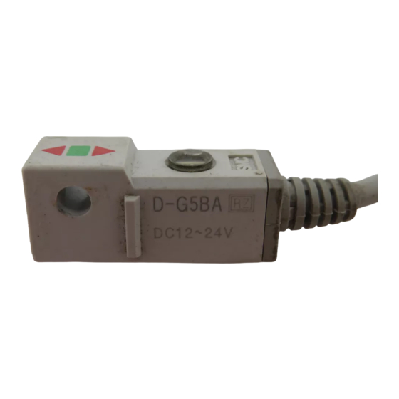
Solid State Auto Switch
Series D-G5BA
(Basic Safety Principles according to EN ISO 13849)
The intended use of the Auto Switch is to detect a position of a magnet in
a pneumatic cylinder. The magnet is installed in e.g. a piston, a slide table,
etc.
This IMM is only applicable for validated products to ISO 13849. Refer to
Doc. No. D-*S-TDP0002.
This manual should be read in conjunction with the current product
catalogue. Keep this manual in a safe place for future reference.
Model Indication Method
D-G5BA__
Lead wire length
L ..... 3 m
Z ..... 5 m
Safety Instructions
These safety instructions are intended to prevent a hazardous situation
and/or equipment damage. These instructions indicate the level of
potential hazard by label of "Caution", "Warning" or "Danger".
(Note1)
To ensure safety be sure to observe ISO4414
, JIS B 8370
other safety practices.
(Note 1):ISO 4414:Pneumatic fluid power - Recommendations for the application of
equipment to transmission and control systems.
(Note 2):JIS B 8370:Pneumatic system axiom.
IMPORTANT MESSAGES
Read this manual and follow its instructions.
Titles such as DANGER, WARNING and CAUTION will be followed by
important safety information which must be carefully followed.
Indicates a hazard with a high level
of risk, which if not avoided, will
result in death or serious injury.
Indicates a hazard with a medium
level of risk, which if not avoided,
could result in death or serious
injury
Indicates a hazard with a low level
of risk, which if not avoided, could
result in minor or moderate injury.
1. The compatibility of pneumatic equipment is the responsibility
of the person who designs the pneumatic system or decides its
specifications.
Since the products specified here are used in various operating conditions,
their compatibility for the specific pneumatic system must be based on
specifications or after analysis and/or tests to meet your specific
requirements.
Safety Instructions (continued)
2. Only trained personnel should operate pneumatically operated
machinery and equipment.
Compressed air can be dangerous if an operator is unfamiliar with it.
Assembly, handling or repair of pneumatic systems should be performed by
trained and experienced operators.
3. Do not service machinery/equipment or attempt to remove
component until safety is confirmed.
1) Inspection and maintenance of machinery/equipment should only be
performed after confirmation of safe locked-out control positions.
2) When equipment is to be removed, confirm the safety process as
mentioned above. Switch off air and electrical supplies and exhaust all
residual compressed air in the system.
3) Before machinery/equipment is re-started, ensure all safety measures to
prevent sudden movement of actuators etc. (Supply air into the system
gradually to create backpressure, i.e. incorporate a soft-start valve).
4. Contact SMC if the product is to be used in any of the following
conditions:
1) Conditions and environments beyond the given specifications, or if
product is used outdoors.
2) Installations in conjunction with atomic energy, railway, air navigation,
vehicles, medical equipment, food and beverage or recreation equipment.
Specifications
D-G5BA
Model number
Wiring style
2 wire type
Application
24V DC Relay, PLC
Load voltage
24 VDC (10~28 VDC)
Load current
5~40mA
Internal voltage
4V or less
drop
Leak current
0,8 mA or less at 24 VDC
Operating time
1 ms or less
Operating
2 colour
indicator LED*
Proof impact
1000 m/s
Vibration
10 to 150 Hz, at the smaller of amplitude 1,5 mm or 20 m/s
resistance
in X, Y, Z directions for 2 hours each (De-energized)
Insulation
50 MΩ or more at 500 VDC mega
(Note2)
and
resistance
Proof voltage
1500 VAC for 1 minute (lead wire, between cases)
Ambient
-10 to +60℃
temperature
Protection
IEC 60529 standard IP67, JIS C 0920
structure
* 2 colour
Operating range ................Red LED is ON.
Proper operating range .....Green LED is ON.
Installation
Actuators
To eliminate the possibility of magnetic interference between switches,
please ensure that, when two or more actuators are used in parallel, they are
kept at least 40 mm apart.
Mid-stroke position sensing
Exercise caution when attempting to detect the piston at mid-position without
stopping, as the switch detection time may be too short, particularly at
relatively high actuator speeds. Detectable max. piston speed can be
obtained by the following formula:
Where possible keep all wiring as short as possible.
If the 2-wire type solid state auto-switch has a large internal voltage drop and
leakage current is too high, it is possible that the load may not operate
correctly due to incorrect load specification.
Installation (continued)
Please confirm the following conditions before operation, and note that the
internal voltage drop and leak current have considerable influence on the
serial and parallel connection of the 2-wire solid state switch.
Leak current influence
I.e. Voltage generated to the load when the power is turned off.
Voltage generated = Auto-switch leak current x load resistance. If this voltage
exceeds the OFF voltage of the load, it is possible that the load may stay ON.
In order to match the condition of the controller-input unit and leak current,
then auto-switch leak current must be less than input unit OFF current.
Internal voltage drop
Should an internal voltage drop occur, then the load supply voltage will also
drop as the switch operates. (Load supply voltage = Source voltage – Internal
voltage drop).
When the load supply voltage becomes lower than the switch ON voltage, the
load may not operate correctly.
Incorrect load voltage
Although the switch will operate correctly, even if the load current is below the
limit of the specification, the indicator light will be 'dimmed'. If the load current
falls to 3mA, or lower, the operation may not start.
Ensure that, if using a load that can generate a surge voltage, i.e. relay or
solenoid valve, a built-in surge protection circuit is installed.
If an auto-switch is to be used to generate an inter-lock signal, which requires
high reliability, then investigate mechanical protection, or place another switch,
double inter-lock style, together. Ensure the correct operation of this Inter-lock
frequently.
Ensure, when installing this product, that enough space is available for
maintenance.
Do not subject this product to any form of impact or vibration damage.
Do not lift an actuator, fitted with an auto-switch, by the switch lead, as stress
may be applied to the inside of the switch.
Ensure auto-switch mounting screw is tightened to the correct torque (see
2
2
Adjust the auto-switch so that the ON position coincides with the centre of the
operating area. If the switch is set to one side or the other of this centre
position then inconsistent operation will occur.
Wiring
Do not apply repeated bending or tensile forces to the connecting wiring as
this may cause disconnection. Bend radius is approximately R40mm or more.
Connect the load before applying power to the switch, failure to do so may
cause excess current to damage the switch.
Ensure wiring is carried out correctly. Not all wiring modes have protection and
the switch may be damaged.
Separate signal lines from power/high voltage lines to prevent 'noise'.
Ensure all wiring is correctly and fully insulated.
DO NOT USE THIS SWITCH IN AN EXPLOSIVE ATMOSPHERE:
Do not use this switch in high magnetic fields, as this will damage the switch
and actuator magnet.
Do not use this switch in water-laden atmospheres, oil or chemical laden
atmospheres.
Do not use this switch in conditions where temperatures are outside of the
switch operating spec.
Protect the switch from weld spatter and accumulation of iron dust etc.
Maintenance
To avoid incorrect operation periodic maintenance should be carried out.
•
Check tightness of mounting screw regularly to prevent possible
movement of the switch from its set position.
•
Regularly check condition of the wiring. Repair insulation damage
immediately or replace the switch.
•
If a red LED is showing this indicates that the switch has moved from the
set position. Re-adjust the switch until the green LED is showing (this is
the optimum position).
Maintenance (continued)
If detection failure accurs i.e. LED remains ON, follow the fault finding chart
below (Fig. 6).
For applications involving contact with water, elasticity and welding, contact
your nearest SMC office. (refer to the end of this Manual).
If the hysteresis, between the ON and OFF position of the switch is incorrect
please consult SMC.
Fig. 1
Outline dimensions (mm)
Fig. 2
Basic wiring
Lead wire colour in brackets indicates products complying with IEC.
Connection with PLC (sequence controller)
Depending on the PLC input specification, the output design of switches
differ (See below).
PLC Input specification
2 wire connection type
Sink input
Sink output mode
Source input
Source output mode
2 wire type (Sink output)
Load
OUT(+)
Brown
Power
Switch
Source
OUT(-)
Blue
Advertisement
Table of Contents

Subscribe to Our Youtube Channel
Related Manuals for SMC Networks D-G5BA Series


Summary of Contents for SMC Networks D-G5BA Series
- Page 1 No. D-*S-TFP34 Safety Instructions (continued) Installation (continued) Maintenance (continued) ORIGINAL INSTRUCTIONS 2. Only trained personnel should operate pneumatically operated Please confirm the following conditions before operation, and note that the Installation & Maintenance Manual machinery and equipment. internal voltage drop and leak current have considerable influence on the serial and parallel connection of the 2-wire solid state switch.
- Page 2 No. D-*S-TFP34 Basic wiring (continued) Setting the switch detection position Troubleshooting 2 wire type (Source output) OUT(+) Brown D-G5BA is a water resistant type autoswitch Power Although this switch has improved properties with regard to oil and water Switch Source resistance, it should not be exposed to cutting oil, which contains additives, OUT(-) Load...
Need help?
Do you have a question about the D-G5BA Series and is the answer not in the manual?
Questions and answers