
Related Manuals for SMC Networks D-P3DW Series


Summary of Contents for SMC Networks D-P3DW Series
- Page 1 No.D-#S-OML0002-C PRODUCT NAME Magnetic Field Resistant 2-color Indication Type Solid State Auto Switch MODEL / Series / Product Number D-P3DW(A)# Series...
-
Page 2: Table Of Contents
Contents Safety Instructions Model Indication Method Names and Functions of products Definition and terminology Mounting and Installation Installation Maintenance Troubleshooting Specification Specifications Dimensions No.D-#S-OML0002-C... -
Page 3: Safety Instructions
Safety Instructions These safety instructions are intended to prevent hazardous situations and/or equipment damage. These instructions indicate the level of potential hazard with the labels of “Caution,” “Warning” or “Danger.” They are all important notes for safety and must be followed in addition to International Standards (ISO/IEC) , and other safety regulations. -
Page 4: Limited Warranty And Disclaimer
Safety Instructions Caution We develop, design, and manufacture our products to be used for automatic control equipment, and provide them for peaceful use in manufacturing industries. Use in non-manufacturing industries is not covered. Products we manufacture and sell cannot be used for the purpose of transactions or certification specified in the Measurement Act. - Page 5 Operator This operation manual is intended for those who have knowledge of machinery using pneumatic equipment, and have sufficient knowledge of assembly, operation and maintenance of such equipment. Only those persons are allowed to perform assembly, operation and maintenance. Read and understand this operation manual carefully before assembling, operating or providing maintenance to the product.
- Page 6 Cylinders or actuators include cylinders, air grippers, rotary actuators, and electrical actuators/cylinders. Design/Selection 1. Confirm the specifications. If the product is used with excess load applied or beyond the specification range, this may cause the product to break or malfunction. We do not guarantee against any damage if the product is used outside of the specification range. 2.
- Page 7 12. Pay attention to leakage current. <2-wire type> Current (leakage current) flows to the load to operate the internal circuit when in the OFF state. Operating current of load (OFF condition) > Leakage current If the criteria given in the above formula are not met, it will not reset correctly (stays ON). Use a 3-wire auto switch if this specification will not be satisfied.
- Page 8 Wiring 1. Confirm proper insulation of wiring. If there is any improper insulation (mixed contact with other circuit, grounding fault, or improper insulation between terminals, etc.) in the wiring, an over-current flows in, causing the auto switch to break. 2. Wire separately from power lines or high voltage lines, avoiding parallel wiring or wiring in the same conduit with these lines.
- Page 9 Operating Environment 1. Never use in an atmosphere of explosive gases, dust. The structure of auto switches is not intended to prevent explosion. This may lead to explosion hazard. 2. Do not use in an area where a magnetic field is generated. Auto switches will malfunction or magnets inside cylinders/ actuators will become demagnetized.
- Page 10 Maintenance 1. Perform the following maintenance periodically in order to prevent possible danger due to unexpected auto switch malfunction. 1) Secure and tighten auto switch mounting screws. If screws become loose or the mounting position is dislocated, retighten them after readjusting the mounting position.
-
Page 11: Model Indication Method
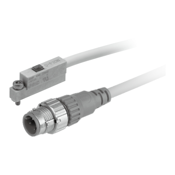
Model Indication Method Names and Functions of products •Names of products D-P3DW D-P3DWA -10- No.D-#S-OML0002-C... -
Page 12: Definition And Terminology
■Definition and terminology Term Meaning Display method in which a red LED turns on when it is in the operating position, and a 2-color indication green LED turns on when it is in the optimum operating range. 2-wire Auto switch Auto switch which has only signal line and COM line. -
Page 13: Mounting And Installation
Mounting and Installation ■Installation When mounting the Auto switch to actuator it should be done with a mounting bracket for actuator. “How to mount” depends on the actuator type and tube I.D. Please refer the actuator catalogue. When the Auto switch is newly mounted, please prepare the mounting bracket for actuator after confirming that the actuator has a built in magnet. -
Page 14: Maintenance
Maintenance How to reset the product for power loss or forcible de-energizing Regarding set up, contents of the program may be maintained by customer's application systems. Be sure to confirm safety when returning operation of the actuator because it could have been stopped in an unstable condition. -
Page 15: Troubleshooting
Troubleshooting When the Auto switch falls in operation failure, identify the trouble with the following flow chart. A failure of the Auto switch might depend on operating environment (application etc.) Contact type: Normally open (normal direction) output The switch Is the actuator Misapplication does not detect applicable? - Page 16 •Trouble list Trouble Investigation to find possible Trouble Possible cause Countermeasure cause Malfunction due The effect of magnetic field Place a magnetic shield plate to The Auto switch to magnetic field generated by adjacent actuator the actuator. output does not turn off.
- Page 17 Trouble Investigation to find possible Trouble Possible cause Countermeasure cause Adjust power supply voltage to a given value. Power supply Power supply voltage “Power supply (Refer to page failure (zero or extremely low) voltage or Load voltage” in Specifications.) Correct wiring. Voltage (load) applied to the Auto “Internal Incorrect wiring...
- Page 18 Trouble Investigation to find possible Trouble Possible cause Countermeasure cause Improper setting Move the Auto switch to proper Detection close to the limit of (mounting) position (near the center of the Auto switch operating angle position Auto switch operating angle). Looseness of the Auto switch Displacement Fix to proper position at the...
-
Page 19: Specification
Specification ■Specifications PLC: Programmable Logic Controller Auto switch model D-P3DW(A) Wiring 2-wire Output Applicable load 24 VDC Relay / PLC Load voltage 24 VDC (20 to 28 VDC) Load current 6 to 40 mA Internal voltage drop 5 V or less Current leakage 1 mA or less Operating time... -
Page 20: Dimensions
■Dimensions D-P3DW(L)(Z) D-P3DWSC, P3DWSE Common : Mounting the white heat shrinking tube with only D-P3DWSE. -19- No.D-#S-OML0002-C... - Page 21 D-P3DWA(L)(Z) D-P3DWASC, D-P3DWASE Common : Mounting the white heat shrinking tube with only D-P3DWASE. -20- No.D-#S-OML0002-C...
- Page 22 Revision history A: Housing, thread and connector changed. B: Addition of D-P3DWA C: Revised content in accordance with Safety Instructions. [April 2024] Tel: + 81 3 5207 8249 Fax: +81 3 5298 5362 https://www.smcworld.com Note: Specifications are subject to change without prior notice and any obligation on the part of the manufacturer. ©...
Need help?
Do you have a question about the D-P3DW Series and is the answer not in the manual?
Questions and answers