
Related Manuals for onsemi NIS3071


Summary of Contents for onsemi NIS3071
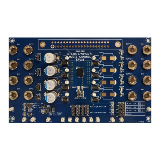
- Page 1 NIS(V)3071 Evaluation Board User’s Manual EVAL BOARD USER’S MANUAL Figure 1. Evaluation Boa Figure 2. Features of Evaluation Board © Semiconductor Components Industries, LLC, 2015 August, 2023 Rev. 1...
- Page 2 NIS3071 EVB Manual Figure 3. Bill of Materials Figure 4. Evaluation Board Schematic http://onsemi.com...
- Page 3 NIS3071 EVB Manual Figure 5. Evaluation Board Layout Image (6 layers) Instructions Caution: Observe all precautions while testing this evaluation board (wear safety glasses, do not connect potentially dangerous high voltages, be sure to not make incorrect reverse connections). Do NOT exceed a DC input voltage of 60V.
- Page 4 • Ex. Pull Enable2 high by connecting a jumper across top pins of JEN1. • Note: All enables are pulled high internally by NIS3071 if left floating. • Controlling Enables 1. Locate the 4 Test Points on the bottom of the board labeled TPEN1, 2, 3, and 4.
- Page 5 NIS3071 EVB Manual Multi-Channel Use • An additional functionality of the device is the ability to operate each channel independently of the others, each with their own input, output, enable, and protection. • Two Rail Configuration Test Parallel Channels 2 and 3 (inputs and enables) using jumpers as described in the above section.
- Page 6 NIS3071 EVB Manual Turn on Time • The turn on time (or slew rate) of the output can be adjusted by connecting a capacitor from the dvdt pin to ground. In this EVB’s case, there are 2 different capacitors to choose from that will show this functionality effectively.
- Page 7 NIS3071 EVB Manual • is a threshold current that, when reached or exceeded for longer than 1.5ms, will turn off the eFuse. The value of I is set by R and that relationship can be seen in Figure 5 of the datasheet.
- Page 8 NIS3071 EVB Manual Figure 11. Output Turn Off due to I Event (R = 30k) Thermal Shutdown • When the temperature of the eFuse reaches 175 C, it will enter thermal shutdown to protect itself from damage. • TS Test 1.