Table of Contents
Advertisement
Quick Links
Advertisement
Table of Contents

Related Manuals for Extech Instruments GX930


Summary of Contents for Extech Instruments GX930
- Page 1 USER GUIDE MODEL GX900 – GRAPHICAL DMM MODEL GX930 – DMM / DIGITAL OSCILLOSCOPE ...
-
Page 2: Introduction
Please visit the Extech Instruments website (www.extech.com) for the latest versions of Manuals, Software, Product updates, and other current information. GX900 ‐ KEY FEATURES The GX900 measures AC/DC Voltage/Current (including remote Clamp current), Resistance, Capacitance, Frequency (electrical and electronic), RPM, Duty Cycle, dBm/dBV, Diode, Continuity, and Temperature The GX930 DMM measures AC/DC Voltage/Current (including remote Clamp current), Resistance, Capacitance, Frequency (electrical and electronic), Diode, Continuity, and Temperature Built‐in datalogger and trend features store measurement data with convenient recall functionality Maximum reading (MAX) and Minimum Reading (MIN) memory features Reading HOLD feature for freezing displayed information (with Auto Hold) Intuitive TFT color LCD display and convenient keypad push‐button control On‐screen HELP utility for user hints and application information Quick A/D conversion sample rates with low pass AC filtering Internal real‐time calendar clock for time stamping Industrial strength meter housing GX900-GX930-EN V1.1 5/14 ... -
Page 3: Gx930 - Key Features
Extech Instruments GX930 ‐ KEY FEATURES Measures AC/DC Voltage/Current, Resistance, Capacitance, Frequency (electrical and electronic), Duty Cycle, Diode, Insulation, Continuity, and Thermocouple Temperature New design, compact size/portable TFT color LCD with clear and stable waveform display Real time sample rate: 500 — 50M samples/second Internal memory storage: 3000 data points Trigger function: Rising edge, Falling edge Automatic search utility 10 sets of waveform storage/output; waveform data can be transmitted via Bluetooth USB PC interface Cursor based operation Multi‐screen display for channel waveform and FFT waveform Simple Menu navigation On‐screen Help utility Includes 1:1 probe with adaptor and battery charger GX900-GX930-EN V1.1 5/14 ... -
Page 4: Table Of Contents
Extech Instruments TABLE OF CONTENTS INTRODUCTION .................... 2 GX900 ‐ KEY FEATURES .................. 2 GX930 ‐ KEY FEATURES .................. 3 TABLE OF CONTENTS .................. 4 SAFETY ...................... 7 INTERNATIONAL SAFETY SYMBOLS .............. 7 IEC1010 OVERVOLTAGE INSTALLATION CATEGORIES ........ 7 CAUTIONS ...................... 8 SAFETY INSTRUCTIONS – INPUT PROTECTION LIMITS ........ 9 FCC COMPLIANCE ................... 10 INDUSTRY CANADA (IC) COMPLIANCE ............ 11 DIGITAL MULTIMETER INSTRUCTIONS ............. 1 2 DESCRIPTIONS .................... 12 METER DESCRIPTION .................. 12 INPUT TERMINAL DESCRIPTION .............. 12 KEYPAD DESCRIPTION .................. 13 ... - Page 5 RESISTANCE MEASUREMENTS ................ 22 CONTINUITY CHECK .................. 23 DIODE TEST ..................... 23 TEMPERATURE MEASUREMENTS .............. 24 CAPACITANCE MEASUREMENTS .............. 25 FREQUENCY, DUTY CYCLE, PULSE WIDTH, and PERIOD MEASUREMENTS (ELECTRONIC) .................... 25 RPM MEASUREMENTS ................... 26 COUNTER MEASUREMENTS ................ 26 FUNCTIONS AND FEATURES ................ 2 7 FUNCTION MENU BASICS ................ 27 THE ‘HELP’ UTILITY .................. 27 AUTOMATIC AND MANUAL RANGING ............ 28 AC AND DC SIGNALS .................. 28 MINIMUM (MIN) AND MAXIMUM (MAX) READINGS ........ 29 CAPTURING PEAK VALUES ................ 30 RELATIVE MODE ..................... 30 DATA HOLD AND AUTO‐HOLD MODE ............ 31 STORING INDIVIDUAL SCREEN‐SHOTS ............. 3 1 VIEWING MEMORY DATA ................ 31 VIEW TREND DATA .................. 32 RECORDING MEASUREMENTS (DATALOGGING) .......... 3 3 GX900-GX930-EN V1.1 5/14 ...
- Page 6 AUTOMATIC POWER OFF ................ 3 7 TIME AND DATE FORMATS ................ 3 8 NUMERIC FORMAT .................. 3 8 LANGAUGE FORMAT .................. 3 8 DIGITAL OSCILLOSCOPE INSTRUCTIONS ............ 3 9 MAIN OSCILLOSCOPE DISPLAY DESCRIPTION .......... 39 OSCILLOSCOPE FUNCTION TEST .............. 40 OSCILLOSCOPE PROBE AND CONNECTOR ............ 40 BATTERY AND FUSE REPLACEMENT .............. 4 1 BATTERY REPLACEMENT ................ 41 FUSE REPLACEMENT .................. 41 SPECIFICATIONS .................... 4 2 GENERAL SPECIFICATIONS ................ 42 ELECTRICAL SPECIFICATIONS ................ 43 GX900-GX930-EN V1.1 5/14 ...
-
Page 7: Safety
Equipment of OVERVOLTAGE CATEGORY I is equipment for connection to circuits in which measures are taken to limit the transient over‐voltages to an appropriate low level. Examples include protected electronic circuits. OVERVOLTAGE CATEGORY II Equipment of OVERVOLTAGE CATEGORY II is energy‐consuming equipment to be supplied from the fixed installation. Examples include household, office, and laboratory appliances. OVERVOLTAGE CATEGORY III Equipment of OVERVOLTAGE CATEGORY III is equipment in fixed installations. Note – Examples include switches in the fixed installation and some equipment for industrial use with permanent connection to the fixed installation. OVERVOLTAGE CATEGORY IV Equipment of OVERVOLTAGE CATEGORY IV is for use at the origin of the installation. Examples include electricity meters and primary over‐current protection equipment. GX900-GX930-EN V1.1 5/14 ... -
Page 8: Cautions
Always remove the test leads before replacing the battery or fuses. Inspect the condition of the test leads and the meter itself for any damage before operating the meter. Use great care when making measurements if the voltages are greater than 25VAC rms or 35VDC. These voltages are considered a shock hazard. Warning! This is a class A equipment. This equipment can cause interference in residential areas; in these cases the operator may be required to take steps to avoid or minimize the interference. Always discharge capacitors and remove power from the device under test before performing Diode, Resistance, or Continuity tests. Voltage checks on electrical outlets can be difficult and misleading because of the uncertainty of connection to the recessed electrical contacts. Other means should be used to ensure that the terminals are not "live". If the equipment is used in a manner not specified by the manufacturer, the protection provided by the equipment may be impaired. This device is not a toy and must not reach children’s hands. It contains hazardous objects as well as small parts that the children could swallow. Do not leave batteries and packing material unattended; they can be dangerous in the hands of children. In the event that the device is going to be unused for an extended period of time, remove the batteries. Expired or damaged batteries can cause cauterization on contact with the skin. Always, therefore, use suitable gloves in such cases. Ensure that the batteries are not short‐circuited. Never incinerate batteries. GX900-GX930-EN V1.1 5/14 ... -
Page 9: Safety Instructions - Input Protection Limits
Input Protection Limits Function Maximum Input V DC or V AC 1000V DC/AC rms mA AC/DC 800mA 1000V fast acting fuse 10A 1000V fast acting fuse (20A for 30 A AC/DC seconds max every 15 minutes) Frequency, Resistance, Capacitance, Duty Cycle, Diode 1000VDC/AC rms Test, Continuity Temperature 1000VDC/AC rms 2. USE EXTREME CAUTION when working with high voltages. 3. DO NOT measure voltage if the voltage on the "COM" input jack exceeds 1000V above earth ground. 4. NEVER connect the meter leads across a voltage source while the function switch is in the current, resistance, or diode mode. Doing so can damage the meter. 5. ALWAYS discharge filter capacitors in power supplies and disconnect the power when making resistance or diode tests. 6. ALWAYS turn off the power and disconnect the test leads before opening the covers to replace the fuse or batteries. 7. NEVER operate the meter unless the back cover and the battery and fuse covers are in place and fastened securely. 8. If the equipment is used in a manner not specified by the manufacturer, the protection provided by the equipment may be impaired. GX900-GX930-EN V1.1 5/14 ... -
Page 10: Fcc Compliance
This equipment complies with FCC RF radiation exposure limits set forth for an uncontrolled environment. To maintain compliance with FCC RF exposure compliance requirements, avoid direct contact to the transmitting antenna during transmission. WARNING: Changes or modifications not expressly approved by the party responsible for compliance could void the user's authority to operate the equipment. GX900-GX930-EN V1.1 5/14 ... -
Page 11: Industry Canada (Ic) Compliance
This equipment complies with RSS 102 RF radiation exposure limits set forth for an uncontrolled environment. To maintain compliance with RSS 102 RF exposure compliance requirements, avoid direct contact to the transmitting antenna during transmission. GX900-GX930-EN V1.1 5/14 ... -
Page 12: Digital Multimeter Instructions
Input for 0 A to 10.00 A current (20VA overload for 30 seconds on, 10 minutes off) Input for 0 A to 500 mA current measurements Return terminal for all measurements Input for voltage, continuity, resistance, diode test, conductance, capacitance GX900-GX930-EN V1.1 5/14 ... -
Page 13: Keypad Description
MAX/MIN button Starts and stops the Maximum (MAX) and Minimum (MIN) reading memory OK button Confirms data entry Rotary Switch Selects the primary measurement function; for each, the meter presents a standard display for that function (range, measurement units, and modifiers). See table below: V~ AC voltage measurements V– DC and AC+DC voltage measurements mV DC(AC) millivolts, ac + dc millivolt, Temperature, Clamp Current measurements Resistance, Diode test, capacitance, continuity measurements Hz % Frequency and duty cycle measurements RPM Counter RPM, Counter measurements A AC, dc and ac + dc amps measurements mA AC, dc and ac + dc milliamps measurements uA AC, dc and ac + dc microampere measurements up to 5,000 μA INFO button Opens the information window Backlight button Selects backlight intensity from low to high. Also used to return from an auto‐power off condition GX900-GX930-EN V1.1 5/14 ... -
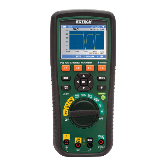
Page 14: Lcd Display Description
3. Primary measurement display area* (minus sign indicates a negative reading). 4. Range indicates the meter’s present range and the ranging mode (auto or manual). 5. Battery level indicates the battery charge level. 6. Time indicates the time set for the internal clock. 7. Mode annunciators indicate the Meter's mode. 8. Mini‐measurement display shows the input value when the primary and secondary displays are busy with a menu screen or pop‐up message. Also shows the lightning bolt icon (when necessary) in this area. 9. Main display provides measurement information regarding the input signal. 10. Date indicates the date set for the internal clock. 11. Beeper indicates the Meter’s audible feedback is enabled (this is not associated with the continuity beeper). 12. Unit indicates the units of measure. Auxiliary Units indicates measurements that use factors instead of units (such as Crest Factor). 13. Blue tooth indicates communication link activity. 14. Relative indicates that the displayed value is relative to a stored reference value. 15. Secondary display shows secondary measurement information concerning the input signal. *The Primary display area indicates the most important value of the selected function. The secondary display contains the bar graph and other values that may be measured in addition to the primary function (for example, frequency measurements along with the primary AC voltage measurement). GX900-GX930-EN V1.1 5/14 ... -
Page 15: Quick Start Guide
Extech Instruments QUICK START GUIDE Step One: Ensure that batteries are installed and are fresh Step Two: Carefully read the Safety section of this Instruction Manual Step Three: Check the Table of Contents to find the section of this Instruction Manual related to the desired test Step Four: Connect the test leads to the meter and to the device under test as described in this Instruction Manual’s section related to the test in question Step Five: Safely perform the test as described in this Instruction Manual Step Six: Read the measurement value on the LCD display Step Seven: Carefully disconnected the meter’s test leads from the circuit or device under test Step Eight: Read the section of this Instruction Manual entitled Features and Functions to learn more about the multitude of meter uses and features Step Nine: Disconnect the test leads from the circuit under test and from the meter and switch OFF the meter before storing. GX900-GX930-EN V1.1 5/14 ... -
Page 16: Measurements
2. If OL appears in the display during a measurement, the value exceeds the selected range. Change to a higher range or use the Auto range mode. DC VOLTAGE MEASUREMENTS CAUTION: Do not measure DC voltages if a motor on the circuit is being switched ON or OFF. Large voltage surges may occur that can damage the meter. 1. Set the function switch to the V‐ position. 2. Insert the black test lead banana plug into the negative COM jack. Insert the red test lead banana plug into the positive V jack. 3. Touch the black test probe tip to the negative side of the circuit. 4. Touch the red test probe tip to the positive side of the circuit. 5. Read the voltage in the display. GX900-GX930-EN V1.1 5/14 ... -
Page 17: Ac Voltage Measurements
CAUTION: Do not measure AC voltages if a motor on the circuit is being switched ON or OFF. Large voltage surges may occur that can damage the meter. 1. Set the function switch to the V~ position. 2. Insert the black test lead banana plug into the negative COM jack. Insert red test lead banana plug into the positive V jack. 3. Touch the black test probe tip to the neutral side of the circuit. Touch the red test probe tip to the “hot” side of the circuit. 4. Read the voltage in the display. dBm/dBV AC MEASUREMENTS The meter is capable of displaying AC voltage as a dB value; relative to 1 milli‐watt (dBm), relative to 1V (dBV), or to a custom reference value. 1. Set the function switch to the V~ position 2. Press the F1 key (MENU) on the LCD and then navigate to the dBm/dBV field using the arrow keys and then press OK. 3. Navigate to the menu item labeled dBm and then press OK. 4. Insert the black test lead banana plug into the negative COM jack. Insert red test lead banana plug into the positive V jack. 5. Touch the black test probe tip to the neutral side of the circuit. Touch the red test probe tip to the “hot” side of the circuit. 6. Read the dBm in the primary display area and read the Voltage in the secondary display area. GX900-GX930-EN V1.1 5/14 ... -
Page 18: Low Pass Filter For Acv Measurements
1. Set the rotary switch to the V~ position 2. Press the F1 key (MENU) 3. Move the menu selector to the LOW PASS field and then press OK 4. Select LPF (Low Pass Filter) and then press OK 5. Press the F3 key (RANGE) and then press the F2 key (MANUAL) 6. Move the menu selector to the 500V field and press the OK key DC/AC MILLIVOLT MEASUREMENTS CAUTION: Do not measure DC/AC voltages if a motor on the circuit is being switched ON or OFF. Large voltage surges may occur that can damage the meter. 1. Set the function switch to the mV position. 2. Press the F1 key (MENU), move the menu selector to the menu item labeled mVDC or mVAC, and then press the OK key 3. Select mVDC or mVAC from the key options and press the OK key. 4. Insert the black test lead banana plug into the negative COM jack. 5. Insert the red test lead banana plug into the positive V jack. 6. Touch the black test probe tip to the negative side of the circuit. 7. Touch the red test probe tip to the positive side of the circuit. 8. Read the voltage in the display. GX900-GX930-EN V1.1 5/14 ... -
Page 19: Current Clamp Measurements
Extech Instruments CURRENT CLAMP MEASUREMENTS 1. This meter offers remote current clamp measurement functionality. 2. Set the rotary switch to the mV position. 3. Press the F1 key (MENU), move the menu selector to the item labeled CLAMP DC/AC, and then press the OK key. 4. Select the item labeled RANGE (0.1~100mV/A) and then press the OK key. 5. Connect the remote clamp to the input terminal jacks ensuring proper polarity. Insert the clamp’s negative lead into the negative COM jack and connect the clamp’s positive lead into the meters positive V jack. 6. Read the measurement in the display. GX900-GX930-EN V1.1 5/14 ... -
Page 20: Dc Current Measurements
Extech Instruments DC CURRENT MEASUREMENTS CAUTION: Do not make 20A current measurements for longer than 30 seconds. Exceeding 30 seconds may cause damage to the meter and/or the test leads. 1. Insert black test lead banana plug into the negative COM jack. 2. For current measurements up to 5000µA DC, set the function switch to the µA position and insert the red test lead banana plug into the µA/mA jack. Press the F1 key (MENU) and select uADC, Press the OK key. 3. For current measurements up to 500mA DC, set the function switch to the mA position and insert the red test lead banana plug into the µA/mA jack. Press the F1 key (MENU) and select mADC, Press the OK key. 4. For current measurements up to 10A DC, set the function switch to the 10A position and insert the red test lead banana plug into the 10A jack. Press the F1 key (MENU) and select ADC, Press the OK key. 5. Remove power from the circuit under test, then open up the circuit at the point where current is to be measured. 6. Touch the black test probe tip to the negative side of the circuit. 7. Touch the red test probe tip to the positive side of the circuit. 8. Apply power to the circuit. 9. Read the current in the display. GX900-GX930-EN V1.1 5/14 ... -
Page 21: Ac Current Measurements
Extech Instruments AC CURRENT MEASUREMENTS CAUTION: Do not make 20A current measurements for longer than 30 seconds. Exceeding 30 seconds may cause damage to the meter and/or the test leads. 1. Insert the black test lead banana plug into the negative COM jack. 2. For current measurements up to 5000µA AC, set the function switch to the µA position and insert the red test lead banana plug into the µA/mA jack. Press the F1 key (MENU) and select uAAC, Press the OK key. For current measurements up to 500mA AC, set the function switch to the mA position and insert the red test lead banana plug into the µA/mA jack. Press the F1 key (MENU) and select mAAC, Press the OK key. For current measurements up to 10A AC, set the function switch to the 10A position and insert the red test lead banana plug into the 10A jack. Press the F1 key (MENU) and select AAC, Press the OK key. 5. Press the key labeled MENU, move the menu selector to the item labeled AC, and then press the OK key 6. Remove power from the circuit under test, then open up the circuit at the point where current is to be measured. 7. Touch the black test probe tip to the neutral side of the circuit. Touch the red test probe tip to the “hot” side of the circuit. 8. Apply power to the circuit. 9. Read the current in the display. GX900-GX930-EN V1.1 5/14 ... -
Page 22: Resistance Measurements
Extech Instruments RESISTANCE MEASUREMENTS WARNING: To avoid electric shock, disconnect power to the unit under test and discharge all capacitors before taking any resistance measurements. Remove the batteries and unplug the line cords. 1. Set the function switch to the Ω CAP position. 2. Insert the black test lead banana plug into the negative COM jack. 3. Insert the red test lead banana plug into the positive Ω jack 4. Touch the test probe tips across the circuit or part under test. It is best to disconnect one side of the part under test so the rest of the circuit will not interfere with the resistance reading. 5. Read the resistance in the display. GX900-GX930-EN V1.1 5/14 ... -
Page 23: Continuity Check
2. Press the F1 key (MENU), move the menu selector to the RESISTANCE, and then press the OK key 3. Move the menu selector to the item labeled CONTINUITY and press the OK key 4. Insert the black lead banana plug into the negative COM jack. 5. Insert the red test lead banana plug into the positive jack. 6. Touch the test probe tips to the circuit or wire under test. 7. If the resistance is less than approximately 35 Ω, the audible signal will sound. If the circuit is open, the display will indicate OL. DIODE TEST 1. Set the function switch to the Ω CAP position 2. Press the F1 key (MENU), move the menu selector to the DIODE field, and then press the OK key 3. Move the menu selector to the item labeled DIODE and press the OK key 4. Insert the black test lead banana plug into the negative COM jack and the red test lead banana plug into the positive V jack. 5. Touch the test probes to the diode under test. Forward voltage will typically indicate 0.400 to 3.200V. Reverse voltage will indicate OL. Shorted devices will indicate near 0V and an open device will indicate OL in both polarities. GX900-GX930-EN V1.1 5/14 ... -
Page 24: Temperature Measurements
Extech Instruments TEMPERATURE MEASUREMENTS 1. Set the function switch to the TEMP position. 2. Press the F1 key (MENU), move the menu selector to the item labeled TEMP, and then press the OK key 3. Move the menu selector to menu item labeled FAHRENHEIT, Celsius, or Kelvin and then press the OK key 4. Insert the Temperature Probe into the input jacks ensuring correct polarity. 5. Touch the Temperature Probe head to the device under test. Maintain contact with the device until the reading stabilizes (about 30 seconds). 6. Read the temperature in the display. To input a temperature offset value, press the F3 key (OFFSET). A message box will appear showing the currently selected offset value. Use the right/left arrow keys to position the cursor over one of the digits (or the polarity sign). Then use the up/down arrows to edit the selected digit or polarity sign. With the desired value displayed, press the F1 key (OK) to confirm the temperature offset. Note: The temperature probe is fitted with a type K mini connector. A mini connector to banana connector adaptor is supplied for connection to the input banana jacks. The adapter connects to COM (‐) and V (+). Note: The temperature range of the supplied thermocouple probe is ‐20 to 250°C (‐4 to 482°F) GX900-GX930-EN V1.1 5/14 ... -
Page 25: Capacitance Measurements
WARNING: To avoid electric shock, disconnect power to the unit under test and discharge all capacitors before taking any capacitance measurements. Remove the batteries and unplug the line cords. 1. Set the rotary function switch to the CAP position. 2. Press the F1 key (MENU), move the menu selector to the menu item labeled CAPACITANCE, and then press the OK key. 3. Select CAPACITANCE and then press the OK key. 4. Insert the black test lead banana plug into the negative COM jack. 5. Insert the red test lead banana plug into the positive V jack. 6. Touch the test leads to the capacitor to be tested. 7. Read the capacitance value in the display FREQUENCY, DUTY CYCLE, PULSE WIDTH, and PERIOD MEASUREMENTS (ELECTRONIC) 1. Set the rotary function switch to the Hz/% position. 2. Press the F1 key (MENU), move the menu selector to the menu item of your choice, either FREQUENCY(Hz), DUTY CYCLE, PULSE WIDTH, or PERIOD, and then press the OK key. 3. Insert the black lead banana plug into the negative COM jack and the red test lead banana plug into the positive Hz jack. 4. Touch the test probe tips to the circuit under test. 5. Read the measurement on the display. GX900-GX930-EN V1.1 5/14 ... -
Page 26: Rpm Measurements
RPM MEASUREMENTS 1. Set the rotary function switch to the RPM position. 2. Insert the black lead banana plug into the negative COM jack and the red test lead banana plug into the positive V jack. 3. Touch the test probe tips to the circuit under test. 4. Read the RPM value on the display. COUNTER MEASUREMENTS 1. Set the rotary function switch to the RPM position. 2. Press the F1 key (MENU), move the menu selector to the item labeled COUNTER, and then press the OK key 3. Move the menu selector to the item labeled START and press the OK key 4. Insert the black test lead into the negative COM jack and the red test lead into the positive V jack. 5. Touch the test probe tips to the circuit under test. 6. Read the Period value on the display. 7. To set the Count Threshold press the F1 key (MENU), move the menu selector to the item labeled COUNTER, and press the OK key 8. Move the menu selector to the menu item labeled THRESHOLD and press the OK key 9. Enter 1 or 2 or 3 using the arrow keys and then press the F1 key to save. Press the F1 key to return to the measure screen. GX900-GX930-EN V1.1 5/14 ... -
Page 27: Functions And Features
Use the keys labeled NEXT and PREV to move from topic to topic. Use the key labeled MORE, UP, and DOWN to scroll through the information a full screen at a time. GX900-GX930-EN V1.1 5/14 ... -
Page 28: Automatic And Manual Ranging
Select one of the above combinations using the FUNCTION and MODE menu as described in the steps below: 1. With the rotary switch set to V, mV, A, mA, or uA press the key labeled MENU 2. Move the menu selector to the menu item labeled MATH 3. Press OK 4. The three labels (AC+DC, AC/DC, and DC/AC) will appear 5. Move the menu selector to the desired menu label 6. Press OK While in any of the three modes described above Peak Measurements, Frequency, Duty Cycle, MAX‐MIN, Relative %, and Period Measurements are not available for use. GX900-GX930-EN V1.1 5/14 ... -
Page 29: Minimum (Min) And Maximum (Max) Readings
To save the MIN‐MAX screen data, the MIN‐MAX session must be ended by pressing the key labeled STOP. After pressing STOP, press the key labeled SAVE. A dialogue box will open prompting for a filename (a name is automatically proposed which can be accepted or changed by the user). Press the key labeled SAVE. Press the key labeled RESTART while MIN‐MAX is running stops the MIN‐MAX session, discards all MIN‐MAX data, and starts a new MIN‐MAX recording session. GX900-GX930-EN V1.1 5/14 ... -
Page 30: Capturing Peak Values
Move the menu selector to the menu item labeled PEAK/CREST F (Crest Factor) and then press the OK key. Move the menu selector to the PEAK or the CREST F label and then press OK to start the PEAK recording session. RELATIVE MODE To activate the Relative mode, press the F1 key (MENU) and move the menu selector next to the menu item labeled REL/REL% and then press the OK key. Move the menu selector to the REL or the REL% label and press OK to start the Relative mode. If the meter is currently in the Relative mode, pressing REL% causes the meter to switch OFF the Relative mode and display Relative percent. GX900-GX930-EN V1.1 5/14 ... -
Page 31: Data Hold And Auto-Hold Mode
(Auto‐Hold threshold) for at least one second. The meter filters open lead conditions so that the meter leads can be moved between test points without triggering a display update. STORING INDIVIDUAL SCREEN‐SHOTS For all measurement functions, a snapshot of the screen data is saved by pressing the key labeled SAVE. VIEWING MEMORY DATA Viewing data stored in the meter’s memory is performed through the SAVE menu as described below: 1. Press the F2 key (SAVE). 2. Position the menu selector on MEMORY and press the OK key. 3. Position the menu selector on VIEW and press the OK key. 4. Position the menu selector on LOG and press the OK key. 5. Press F1 (PREV) or F2 (NEXT) to view your saved data sets. GX900-GX930-EN V1.1 5/14 ... -
Page 32: View Trend Data
If there are previously stored records, press the F1 key (PREV) to page through them or Press the F2 key (NEXT) to scroll in the opposite direction. Press F4 (CLOSE) to return the meter to the normal operating mode. Press the F3 key (TREND) to display the recorded data in a trend‐plot view. Press the F2 key (DELETE) to clear recorded data. Press the F3 key (SUMMARY) to get back to the data summary and Press F4 key (CLOSE) to return to normal operating mode. GX900-GX930-EN V1.1 5/14 ... -
Page 33: Recording Measurements (Datalogging)
7. Press the key labeled START to start recording. 8. The recording session will continue until the allocated memory is consumed, the batteries expire, the rotary switch is moved, or the session is terminated by pressing the key labeled STOP. GX900-GX930-EN V1.1 5/14 ... -
Page 34: Zooming On Trend Data
Meter information such as serial number, model, etc. is also available in the Setup mode. Access to the setup options is available by pressing the F4 key (SETUP). RESET THE METER SETUP OPTIONS The meter’s setup options can be reset to factory default conditions through the Setup menu. 1. Open the setup menu by pressing the F4 key (SETUP). 2. Position the menu selector next to the item labeled RESET and then press the OK key 3. Position the menu selector next to the item labeled SETUP and then press the OK key, press the OK key again. 4. A message will appear asking “Reset settings to Factory Defaults?” to confirm the Reset action. Press the F1 key (OK) or the F4 key (Cancel) to cancel the reset. GX900-GX930-EN V1.1 5/14 ... -
Page 35: Meter Information Screen
The Calibration selection allows a qualified calibration technician to enter a password that grants access to the meter for calibration purposes. 1. Press the F4 key (SETUP) to access the Setup menu. 2. Using the cursor buttons, move the menu selector next to the item labeled Calibration and press OK. 3. Select PASSWORD and press OK. 4. Select EDIT and press OK. 5. Using the menu arrow keys enter a password and Click F1 key (OK) of F4 key (CANCEL). Note: default password is 1234 GX900-GX930-EN V1.1 5/14 ... -
Page 36: Calibration Access
5. Input the current password using the menu keys and press F1 key (OK) or press the F4 key (CANCEL). Calibration instructions are only available to qualified certified technicians. Contact Extech Instruments for further information concerning calibration instructions BLUETOOTH CAPABILITY A Bluetooth communication link can be established allowing the user to monitor the meter from an Android device using the application ExView™. 1. Open the setup menu by pressing the F4 key (SETUP). 2. Position the menu selector next to the INSTRUMENT label and press OK 3. Position the menu selector next to the COMMUNICATE label and press OK 4. Press the F1 key (START) to turn on the Bluetooth™ signal or press the F2 key (STOP) to turn off the Bluetooth™ signal. Note: when the meter is shut off and then back on, the Bluetooth signal will have to be turned back on manually. GX900 SOFTWARE The GX900 meter is supplied with software that will allow you to capture measured data in Real Time and download logged data from the GX900 to the software. Refer to the software’s help file for instructions for use. GX900-GX930-EN V1.1 5/14 ... -
Page 37: Setting The Date And Time
5. Use the up and down arrows to change the selected date or time values. 6. Press the F1 key (OK) to complete and confirm the actions. AUTOMATIC POWER OFF 1. Open the Setup menu by pressing the F4 Key (SETUP). 2. Position the menu selector next to INSTRUMENT and press OK. 3. Position the menu selector next to SETTINGS and press OK. 4. Position the menu selector next to the item labeled POWER OFF and press OK. 5. To set the Auto Power OFF time interval, use the up and down arrows to select the time in minutes (05 to 60). 6. Set the time to zero (00) to disable the Auto Power OFF feature. 7. Press the F1 key (OK) to confirm the selection. 8. Press the F4 key (CANCEL) to return to the normal operating mode without saving the edit. GX900-GX930-EN V1.1 5/14 ... -
Page 38: Time And Date Formats
4. Position the menu selector next to the item labeled TIME FORMAT or DATE FORMAT and press OK to begin editing 5. TIME FORMAT – select F1 (24 HOUR) or F2 (12 HOUR). DATE FORMAT – select F1(MM/DD/YY) or F2 (DD/MM/YY). Press F3 (CANCEL) to exit without changing the format. NUMERIC FORMAT 1. Press the F4 key (SETUP). 2. Position the menu selector next to the item labeled DISPLAY and press OK. 3. Position the menu selector next to the item labeled FORMAT and press OK 4. Position the menu selector next to the item labeled NUMERIC and press OK. 5. Select F1 (0.000) or F2 (0,000) or F4 (CANCEL). LANGAUGE FORMAT 1. Press the F4 key (SETUP). 2. Position the menu selector next to the item labeled DISPLAY and press OK. 3. Position the menu selector next to the item labeled FORMAT and press OK 4. Position the menu selector next to the item labeled LANGAUGE and press OK. 5. Select F1 (ENG) or F4 (CANCEL). GX900-GX930-EN V1.1 5/14 ... -
Page 39: Digital Oscilloscope Instructions
Extech Instruments DIGITAL OSCILLOSCOPE INSTRUCTIONS MAIN OSCILLOSCOPE DISPLAY DESCRIPTION 1. Date and Time 2. Status of current waveform window 3. Remaining battery power 4. Waveform display area 5. Waveform peak value 6. Signal coupling marks, preset amplitude 7. Waveform’s measured frequency 8. Preset sample rate 9. Trigger mode mark 10. Fast display mark 11. Slow display mark 12. Operation prompt bar GX900-GX930-EN V1.1 5/14 ... -
Page 40: Oscilloscope Function Test
Extech Instruments OSCILLOSCOPE FUNCTION TEST Perform a quick functional test to verify the operation of the oscilloscope. 1. Switch ON power 2. Connect the oscilloscope to a signal source. A 110/220V AC power source is a good place to start. 3. Press ‘AUTO’ and the corresponding frequency and peak waveform will be detected in a matter of seconds. 4. If using a 110/220V power source use the down arrow button to set the V/div. User the left/right arrows to set the number of samples per second. OSCILLOSCOPE PROBE AND CONNECTOR The probe provides finger protection from electrical shock. Keep fingers in the safe area behind the protective barrier at all times. GX900-GX930-EN V1.1 5/14 ... -
Page 41: Battery And Fuse Replacement
Observe local, state, and federal regulations with regard to battery disposal. Never dispose of batteries in a fire. Batteries may explode or leak. Never mix battery types. Always install new batteries of the same type. FUSE REPLACEMENT 1. Switch the meter off and remove the test leads from the meter’s input jacks 2. Remove the battery compartment cover. 3. Remove the fuse from the battery compartment by first carefully prying one end loose and then sliding the fuse from its bracket 4. Install only specified replacement fuses 5. Replace the battery compartment cover 800mA/1000V ceramic ‐ 6.3mm x 32mm (SIBA 7017240.0,8) 10A/1000V ceramic ‐ 10mm x 38mm (SIBA 5019906.10) GX900-GX930-EN V1.1 5/14 ... -
Page 42: Specifications
ANSI / NEDA- 5004LC,IEC-CR2032; Normal Voltage: 3.0 Volts; Built-in lithium Typical Capacity: 240 mAh ; Storage 5 Year Chemical type: Lithium polymer, Standard: GB/T Dimensions 9.25 x 4.25 x 2.5” (235 x 108 x 63.5mm) Weight 1.85 lbs. (839g) GX900-GX930-EN V1.1 5/14 ... -
Page 43: Electrical Specifications
<1KHz (1.5% + 25) 50mA AC Current <10KHz (3% + 25) 0.01mA 500mA 0.001A (20A: 30 sec max with reduced accuracy) Accuracy for all AC current ranges are specified from 5% of range to 100% of range GX900-GX930-EN V1.1 5/14 ... - Page 44 50nF[¹] 0.01nF 500nF 0.1nF Capacitance 5µF 0.001µF ±(2% + 40 digits) 50µF 0.01µF 500µF 0.1µF ±(5% +40 digits) 10mF 0.01mF [1] With a film capacitor or better, use relative mode (REL ∆ ) to zero residual. GX900-GX930-EN V1.1 5/14 ...
- Page 45 0.1A-0.0001A Clamp + 0.5% Clamp(AC) 0.1-100mV/A 0.1A-0.0001A Clamp + 0.5% Function Range Resolution Accuracy ±(1.0% reading -50 to 1000°C 0.1°C + 2.5°C) Temperature ±(1.0% reading (type-K) + 4.5°F) -58 to 1832°F 0.1°F (Probe accuracy not included) GX900-GX930-EN V1.1 5/14 ...
- Page 46 Annual calibrations should be performed to verify meter performance and accuracy. Technical support and general customer service is also provided, refer to the contact information provided below. Support Lines: U.S. (877) 439‐8324; International: +1 (603) 324‐7800 Technical Support: Option 3; E‐mail: support@extech.com Repair & Returns: Option 4; E‐mail: repair@extech.com Product specifications are subject to change without notice Please visit our website for the most up‐to‐date information www.extech.com FLIR Commercial Systems, Inc., 9 Townsend West, Nashua, NH 03063 USA ISO 9001 Certified Copyright © 2013 FLIR Systems, Inc. All rights reserved including the right of reproduction in whole or in part in any form www.extech.com GX900-GX930-EN V1.1 5/14 ...
- Page 47 à la réparation ou au remplacement du produit. La garantie définie ci‐dessus est inclusive et aucune autre garantie, écrite ou orale, n’est exprimée ou implicite. Calibrage, réparation et services après‐vente FLIR Systems, Inc. offre des services de calibrage et de réparation pour les produits Extech Instruments que nous commercialisons. Nous fournissons également une certification NIST pour la plupart des produits. Contactez notre service client pour toute information sur les services de calibrage disponibles pour ce produit. Un calibrage doit être effectué chaque année pour vérifier les performances et la précision du mètre. Nous offrons également une assistance technique et un service à la clientèle. Veuillez vous reporter aux coordonnées fournies ci‐dessous. Lignes d’assistance: États‐Unis (877) 439‐8324; international: +1 (603) 324‐7800 Service d’assistance technique : Option 3 ; E‐mail : support@extech.com Réparations et retours : Option 4 ; E‐mail : repair@extech.com Les spécifications produit sont sujettes à modifications sans préavis. Pour les toutes dernières informations, veuillez visiter notre site Web. www.extech.com FLIR Commercial Systems, Inc., 9 Townsend West, Nashua, NH 03063 USA Certifié ISO 9001 Copyright © 2013 FLIR Systems, Inc. Tous droits réservés, y compris la reproduction partielle ou totale sous quelque forme que ce soit. www.extech.com GX900-GX930-EN V1.1 5/14 ...
- Page 48 Llame al Departamento de Servicio al Cliente para solicitar información de calibración para este producto. Para verificar el funcionamiento y precisión se debe realizar la calibración anual. Además se provee Soporte Técnico y servicios generales al cliente, consulte la información de contacto en seguida. Líneas de soporte: EE.UU. (877) 439‐8324; Internacional: +1 (603) 324‐7800 Soporte Técnico Opción 3; correo electrónico: support@extech.com Reparación / Devoluciones: Opción 4; correo electrónico: repair@extech.com Las especificaciones del producto están sujetas a cambios sin aviso Por favor visite nuestra página en Internet para la información más actualizada www.extech.com FLIR Commercial Systems, Inc., 9 Townsend West, Nashua, NH 03063 USA Certificado ISO 9001 Copyright © 2013 FLIR Systems, Inc. Reservados todos los derechos, incluyendo el derecho de reproducción total o parcial en cualquier medio www.extech.com GX900-GX930-EN V1.1 5/14 ...
Need help?
Do you have a question about the GX930 and is the answer not in the manual?
Questions and answers