Extech CB10 - Receptacle Tester Manual
- User manual (8 pages) ,
- User manual (8 pages) ,
- User manual (2 pages)
Advertisement
Introduction
Congratulations on your purchase of the Extech Model CB10 Circuit Breaker Finder and Receptacle Tester. This instrument is shipped fully tested and calibrated and, with proper use, will provide years of reliable service.
Safety
 This symbol adjacent to another symbol, terminal or operating device indicates that the operator must refer to an explanation in the Operating Instructions to avoid personal injury or damage to the meter.

This WARNING symbol indicates a potentially hazardous situation, which if not avoided, could result in death or serious injury.

This CAUTION symbol indicates a potentially hazardous situation, which if not avoided, may result damage to the product.
 This symbol indicates that a device is protected throughout by double insulation or reinforced insulation.
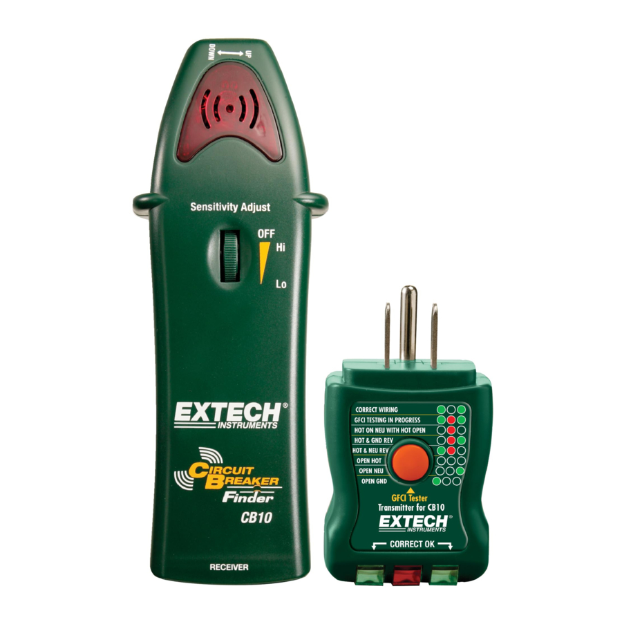
Meter Description

Receiver
- Indicating LED and Beeper
- ON/OFF and Sensitivity adjust
- Transmitter storage plug
Note that battery compartment is located on rear of receiver
Transmitter
- Receptacle LED coding scheme
- GFCI test button
- Receptacle LED's
Specifications
| Operating Voltage | 90 to 120V |
| Operating Frequency | 47 to 63Hz |
| Power supply | 9V battery (receiver) |
| Operating Temperature | 41ºF to 104ºF (5ºC to 40ºC) |
| Storage Temperature | -4ºF to 140ºF (-20ºC to 60ºC) |
| Operating Humidity | Max 80% up to 87ºF (31ºC) decreasing linearly to 50% at 104ºF (40ºC) |
| Storage Humidity | <80% |
| Operating Altitude | 7000ft. (2000meters) maximum. |
| Weight | 5.9oz (167g) |
| Dimensions | 8.5" x 2.2" x 1.5" (215 x 56 x 38mm) |
| Approvals | UL CE |
| UL Listed | The UL mark does not indicate that this product has been evaluated for the accuracy of its readings. |
Operation
Always test on a known good circuit before use.
Refer all indicated problems to a qualified electrician.
Locating a Circuit Breaker or Fuse
The transmitter injects a signal onto the circuit which can be detected by the receiver. The receiver will beep when the signal is detected. The sensitivity adjustment allows for tracing and pinpointing the exact circuit breaker or fuse protecting the selected circuit.

- Plug the Transmitter / Receptacle Tester into a powered outlet. The two green LED's should illuminate.
- Rotate the Receiver's Sensitivity adjustment from the OFF position to the HI position. The red LED should turn on. If the LED does not turn on, replace the battery.
- Test the operation of the Receiver by placing it in close proximity to the transmitter. The receiver should beep and the LED should flash.
- At the breaker panel, set the sensitivity to the HI position and hold the receiver as indicated by the "UP – DOWN" label.
- Move the receiver along the row of breakers until the selected circuit is identified by the beep and flashing light.
- Reduce the sensitivity as needed to pinpoint the exact circuit breaker controlling the circuit.
Receptacle Wiring Test

- Plug the Transmitter / Receptacle tester into the outlet.
- The three LED's will indicate circuit condition. The diagram lists all of the conditions that the CB10 can detect. The LED's in this diagram represent the view from the GFCI button side of the transmitter. When viewing the other side of the transmitter the LED's will be a mirror image of those shown here.
- The tester will not indicate the quality of the ground connection, 2 hot wires in a circuit, a combination of defects, or reversal of ground and neutral conductors.
Receptacle GFCI Test
- Before using the tester, press the TEST button on the installed GFCI receptacle, the GFCI should trip. If it does not trip, do not use the circuit and call a qualified electrician. If it does trip, press the RESET button on the receptacle.
- Plug the Transmitter / Receptacle tester into the outlet. Verify that the wiring is correct as described above.
- Press and hold the test button on the tester for at least 8 seconds, the indicator lights on the tester will shut off when the GFCI trips.
- If the circuit does not trip, either the GFCI is operable but the wiring is incorrect, or the wiring is correct and the GFCI is inoperable.
Replacing the Battery
- When the battery drops below the operating voltage the receiver's LED will not light. The battery should be replaced
- Remove receiver battery cover by removing the screw using a Philips head screwdriver. (The Transmitter is line powered.)
- Install 9 volt battery observing the correct polarity.
- Re-install battery cover
- Dispose of the old battery properly.
Calibration and Repair Services
Teledyne FLIR offers calibration and repair services for the Extech brand products we sell. We offer NIST traceable calibration for most of our products. Contact us for information on calibration and repair availability, refer to the contact information below. Annual calibrations should be performed to verify meter performance and accuracy. Product specifications are subject to change without notice. Please visit our website for the most up-to-date product information: www.extech.com.
Contact Customer Support
Customer Support Telephone List: https://support.flir.com/contact
Calibration, Repair, and Returns: repair@extech.com
Technical Support: https://support.flir.com
www.extech.com
Documents / Resources
References
Download manual
Here you can download full pdf version of manual, it may contain additional safety instructions, warranty information, FCC rules, etc.
Advertisement


Need help?
Do you have a question about the CB10 and is the answer not in the manual?
Questions and answers