
Related Manuals for Schwinn 530


Summary of Contents for Schwinn 530
- Page 1 This product is compliant with the ASSEMBLY MANUAL / OWNER’S MANUAL applicable CE requirements.
-
Page 2: Table Of Contents
For details regarding product warranty or if you have questions or problems with your product, please contact your local Schwinn distributor. To find your local distributor, go to: www.nautilusinternational.com Nautilus, Inc., www.nautilusinternational.com | Nautilus, Inc., 18225 NE Riverside Parkway, Portland, OR 97230 USA | Printed in China | © 2016 Nautilus, Inc. | ® indicates trademarks registered in the United States. These marks may be registered in other nations or otherwise protected by common law. Schwinn, the Schwinn Quality logo, Schwinn 530, Schwinn Connect, Nautilus, Bowflex, and Universal are trademarks owned by or licensed to Nautilus, Inc. Polar , OwnCode , MyFitnessPal... -
Page 3: Important Safety Instructions
• If replacement parts are necessary, use only genuine Schwinn replacement parts and hardware. Failure to use genuine replacement parts can cause a risk to users, keep the machine from operating correctly and void the warranty. - Page 4 • This product contains magnets. Magnetic fields can interfere with the normal use of certain medical devices at a close range. Users may come into proximity of the magnets in the assembly, maintenance, and/or use of the product. Given the obvious importance of these devices, such as a pacemaker, it is important that you consult with your medical provider in connection with the use of this equipment. Please consult the “Safety Warning Labels and Serial Number” section to determine the location of the magnets on this product.
- Page 5 • Keep power cord away from heat source and hot surfaces. • This machine must be connected to an appropriate, dedicated electrical circuit. Nothing else must be connected to the circuit. • Always connect the power cord to a circuit capable of handling at least 10 amperes with no other loads applied. •...
-
Page 6: Safety Warning Labels / Serial Number
SAFETY WARNING LABELS AND SERIAL NUMBER WARNING! WARNING! - Moving parts can crush Keep young children away and cut. from this machine at all - Keep guards in place. times. Contact with the - Lock out power before moving surface may result in servicing. -
Page 7: Earthing Instructions
Earthing Instructions This product must be electrically earthed. If a malfunction occurs, correct earthing decreases the risk of electric shock. The power cord is equipped with an equipment-earthing conductor, and must be connected to an outlet that is properly installed and earthed. The electrical wiring must comply with all applicable local and provincial standards and requirements. -
Page 8: Specifications
SPECIFICATIONS / BEFORE ASSEMBLY Maximum User Weight: 136 kg (300 lbs) Total Surface Area (footprint) of equipment: 16387 cm 146.3 cm ( 57.6” ) Power Requirements: Operational Voltage: 220V - 240V AC, 50Hz Operating Current: Maximum Inclined Deck Height: 38.4 cm (15.1 inches) 183.3 cm ( 72.2” ) Assembled Weight: Approx. 90.7 kgs (200 lbs) 89.4 cm... -
Page 9: Parts
PARTS Item Description Item Description Console Assembly Base Assembly ( Console Backing Base Shroud, Left Tray, Left Upright, Left Tray, Right Handlebar Shroud, Left Upright, Right Power Cord Handlebar Shroud, Right Safety Key Base Shroud, Right Media Cable (not shown) DO NOT CUT the Shipping Strap on the Base Assembly until it has been placed face up as shown in the appropriate work space (... -
Page 10: Hardware
HARDWARE / TOOLS Item Description Item Description Socket Head Hex Screw, M8x50 Self Tapping Screw, M3.9x16 Socket Head Hex Screw, M8x16 Lock Washer, M8 Phillips Head Screw, M5x14 Flat Washer, M8 Note: Select pieces of Hardware have been provided as spares on the Hardware Card. Be aware that there may be remaining Hardware after the proper assembly of your machine. Tools Included 6 mm... -
Page 11: Assembly
ASSEMBLY DO NOT CUT the Shipping Strap on the Base Assembly until it has been placed face up as shown in the appropriate work space. 1. Fold the Walking Deck on the Base Assembly Cut the Shipping Strap on the Base Assembly. Make sure that there is safe clearance around, on and above your tread- mill. - Page 12 2. Connect the Input/Output (I/O) Cables and Attach the Uprights to Frame Note: Do not crimp cables. Do not fully tighten Hardware until instructed.
- Page 13 3. Unfold the Walking Deck Slightly push the walking deck forward toward the front of the machine. With your left foot lightly push the top part of the hydraulic lift forward until the locking tube releases and you can pull the walking deck slightly toward the rear of the machine.
- Page 14 4. Remove the Console Backing from the Console Assembly Note: Dispose of the pre-installed hardware.
- Page 15 5. Connect the I/O Cables and Attach the Console to Frame Assembly Note: Do not crimp the Cables.
- Page 16 6. Fold the Walking Deck and tighten ALL Hardware from previous steps 7. Place the Base Shrouds onto the Frame Assembly, and then unfold the Walking Deck Note: Unfold the Walking Deck after the Base Shrouds have been placed onto the Frame Assembly. The Base Shrouds do not use hardware or snap onto the Frame Assembly.
- Page 17 8. Attach the Console Backing to the Frame Assembly NOTICE: Attach the hardware marked below with the ( * ) first, then the hardware with the ( ** ), followed by the remaining hardware.
- Page 18 9. Attach the Handlebar Shrouds to the Frame Assembly NOTICE: The parts have a right (“ R ”) and left (“ L ”) mark to assist with assembly.
- Page 19 10. Snap the Trays into the Console Assembly NOTICE: Tray edges should be flush with the face of Console.
- Page 20 11. Connect the Power Cord and Safety Key to the Frame Assembly Connect this machine to a properly earthed outlet only (see Earthing Instructions). 12. Final Inspection Inspect your machine to ensure that all hardware is tight and components are properly assembled. Be sure to record the serial number in the field provided at the front of this manual.
-
Page 21: Moving The Machine
BEFORE YOU START Moving the Machine The machine can be moved by one or more persons. Use caution when you move the machine. The treadmill is heavy and can be awkward. Make sure that your own physical strength is capable of moving the machine. -
Page 22: Unfolding The Machine
Carefully tilt the base frame of the folded treadmill a small distance back on the transport wheels while grasping the support bar. Do not use the Console, handlebars, or lifted walking deck to lift or move the treadmill. Damage to the treadmill can occur. -
Page 23: Leveling The Machine
Leveling the Machine The machine needs to be leveled if your workout area is uneven. To adjust: Place the machine in your workout area. 2. A djust the levelers until they all contact the floor. Do not adjust the levelers to such a height that they detach or unscrew from the machine. Injury to you or damage to the machine can occur. -
Page 24: Features
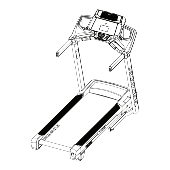
FEATURES Handlebar Motor Cover Ergo Bar Base Contact Heart Rate (CHR) Sensors Leveler Emergency Safety Key Port Transport Wheel Hydraulic Lift Console Dampener USB Port Side Foot Support Rails MP3 Input Walking Belt and Deck Media Tray Power Switch Speaker AC Inlet Storage Tray Telemetry Heart Rate (HR) Receiver (not shown) -
Page 25: Console Features
Console Features The Console provides important information about your workout and lets you control the resistance levels while you exercise. The Console features touch control buttons to navigate you through the exercise programs. Goal Track Achievement Lights Pre-Set Pre-Set Speed Incline Buttons Buttons Incline Speed Enter Enter Button Button INCLINE SPEED Fan Button Console Display Goal Track Achievement Lights- when an achievement level is reached or a result is reviewed, the achievement indicator light will activate. - Page 26 Incline Enter button- Activates the incline motor to adjust the Walking Deck to the selected Pre-Set Incline value. START button- Begins a Quick Start workout, begins a Program Workout after customized for the User, or resumes a paused workout. FAN button- Controls 3-speed fan PAUSE / STOP button- Pauses an active workout, ends a paused workout, or exits to the previous menu Pre-Set Speed buttons- Selects a speed value for the Walking Belt.
- Page 27 Option Guides The Option Guides inform the User where they are in a list of options with the MORE and PREVIOUS Options. If the MORE Options (decrease arrow) is active, then there are additional options that can be viewed by pushing the Decrease () button.
- Page 28 Track Your Results at www.schwinnconnect.com Take advantage of the Schwinn Connect™ website to see your progress over time and share your data with MyFitnessPal . Review your workouts and results away from the machine when convenient for you. The Schwinn ®...
- Page 29 Remote Heart Rate Monitor Monitoring your Heart Rate is one of the best procedures to control the intensity of your exercise. Contact Heart Rate (CHR) sensors are installed to send your heart rate signals to the Console. The Console can also read telemetry HR sig- nals from a Heart Rate Chest Strap Transmitter that operates in the 4.5kHz - 5.5kHz range. Note: The heart rate chest strap must be an uncoded heart rate strap from Polar Electro or an uncoded POLAR ®...
- Page 30 The graph is a brief guideline, describing the generally suggested target heart rates based on age. As noted above, your optimal target rate may be higher or lower. Consult your physician for your individual target heart rate zone. Note: As with all exercises and fitness regimens, always use your best judgment when you increase your exercise time or intensity.
-
Page 31: Operations
OPERATIONS What to Wear Wear rubber-soled athletic shoes. You will need the appropriate clothes for exercise that allow you to move freely. How Often Should You Exercise Consult a physician before you start an exercise program. Stop exercising if you feel pain or tightness in your chest, become short of breath, or feel faint. Contact your doctor before you use the machine again. Use the values calculated or measured by the machine’s computer for reference purposes only. -
Page 32: Power Up / Idle Mode
• If there is a need to immediately stop the machine, pull out the Safety Key to shut off the power to the Belt and Incline Motors. This will quickly stop the belt (brace yourself- this is an abrupt stop) and clear the workout. Push the PAUSE/STOP button to stop the belt and pause the program. -
Page 33: Quick Start Program
Push OK to set. The Console goes to the Power-Up Mode screen. Note: To adjust these selections, consult the “Console Set-Up Mode” section. Quick Start ( Manual ) Program The Quick Start ( Manual ) program lets you start a workout without entering any information. During a Manual Workout, each column represents a 2 minute time period. - Page 34 3. The Console display shows the EDIT prompt and the current User Profile name. Push OK to start the Edit User Profile option. T o exit the User Profile options, push the PAUSE/STOP button and the console will go back to the Power-Up Mode screen. 4. The Console display shows the NAME prompt and the current User Profile name. Note: The User name will be blank if this is the first edit.
- Page 35 The Upper Display shows the current value setting: “ON” or “OFF”. Push the Increase() or Decrease() buttons to change the value. The default is “ON”. Push the OK button to set the Telemetry Heart Rate Receiver to active. 10. The Console will go to the Power-Up Mode screen with the user selected. Reset a User Profile 1.
-
Page 36: Profile Programs
QUICKSTART (press and hold to customize PERFORMANCE 1: program) QUICK GOAL and PACER brickyard (s): QUICK GOAL Profile Programs Distance These programs feature different incline angles of the deck and belt speeds based on the maximum and minimum speed Time Default MAX SPEED : 3 mph supplied by the user. The user can also manually adjust the incline and speed values at any time during a workout. The Calories Profile Programs are organized into Categories (Quick Goal, Heart Health, Weight Control, Interval, Train, and Custom). - Page 37 this program, Console uses BEST pace from Aerobic 75% Default MAX SPEED : 7 mph ENDURANCE 2: previous workout if this distance has not been Anaerobic85% Boot Camp: [ 1299 machine ] previously done. INTERVAL LOW IMPACT OW IMPACT/INCLINE: HIIT/SPEED HIIT/SPEE MAX SPEED : 1 mph INTERVAL-DUAL (Incline and Speed)
- Page 38 6. Use the Increase() or Decrease() buttons to adjust the Maximum Speed of the Belt, and push OK. The Profile Program will adjust so the Maximum Speed value is the highest Speed of the Profile Program when accepted. During a Workout, the User can directly adjust the speed of the belt above the Maximum Speed setting if desired. Use the Increase() or Decrease() buttons to select a type of Goal (Distance, Time or Calories), and push OK. 8. U se the Increase() or Decrease() buttons to adjust the workout value, and push OK.
-
Page 39: Pausing Or Stopping
3. Push the Increase() or Decrease() buttons to set the Heart Rate (HR) value for the workout, and push OK. 4. Push the Increase() or Decrease() buttons to set the Minimum Speed, and push OK. 5. Push the Increase() or Decrease() buttons to set the Maximum Speed, and push OK. 6. -
Page 40: Goal Track Statistics
GOAL TRACK Statistics (and Achievements) The statistics from every workout are recorded to a User Profile. To view the GOAL TRACK statistics of a User Profile: 1. From the Power-Up screen, push the User button to select a User Profile. 2. Push the Goal Track button to enter the Goal Track mode. Note: To exit the Goal Track mode, push the Goal Track button and the console will go back to the Power-Up Mode screen. 3. The Console will display the “LONGEST WORKOUT”, the workout values and activate the corresponding Achievement light. -
Page 41: Console Setup Mode
CONSOLE SETUP MODE The Console Setup Mode lets you control the sound settings ( on/off ), adjust the date and time, or see maintenance statistics (Total Run Hours and Software Version– for service technician use only). Hold down the PAUSE/STOP button and Right button together for 3 seconds while in the Power-Up Mode to go into the Console Setup Mode. -
Page 42: Maintenance
MAINTENANCE Read all maintenance instructions fully before you start any repair work. In some conditions, an assistant is required to do the necessary tasks. Equipment must be regularly examined for damage and repairs. The owner is responsible to make sure that regular maintenance is done. -
Page 43: Adjusting The Belt Tension
NOTICE: T o prevent damage to the finish of the machine or Console, do not clean with a petroleum based sol- vent. Do not apply too much moisture to the Console. Adjusting the Belt Tension If the walking belt starts to slip during use, it is necessary to adjust the tension. Your treadmill has tension bolts at the rear of the treadmill. -
Page 44: Lubricating The Walking Belt
Stand at the rear of the treadmill to see which direction the belt moves. If the belt moves to the left, turn the left belt adjustment bolt 1/4 turn clockwise and the right belt adjustment bolt 1/4 turn counterclockwise. If the belt moves to the right, turn the left adjustment bolt 1/4 turn counterclockwise and the right adjustment bolt 1/4 turn clockwise. - Page 45 Do not connect the power cord or try to operate the treadmill in the folded position. Apply a few drops of the lubricant to the inner surface of the belt for the entire width of the belt. A very thin layer of silicone lubricant on the entire deck below the belt is desired.
-
Page 46: Maintenance Parts
Maintenance Parts Console Assembly Tray, Right Handlebar Shroud, Right Safety Key Port Right Upright Cable Upright, Left Upright, Right Base Shroud, Left Contact Heart Rate Sensor Base Shroud, Right Handlebar Shroud, Left Console Cable Base Cable Power Cord Tray, Left Base Assembly... - Page 47 Maintenance Parts ( Frame ) Front Back Fuse Base Support Incline Adjuster Power Switch Deck Cushioners Pivot Assembly Power Input Transport Wheel Belt Tensioner Motor Cover Leveler Rear Roller Cover Side Foot Support Rails Lifting Cylinder GG Motor Control Board (MCB) Cover...
-
Page 48: Troubleshooting
TROUBLESHOOTING Condition/Problem Things to Check Solution No display/partial display/ Check electrical (wall) Make sure unit is plugged into a functioning wall outlet. Test the unit will not turn on outlet outlet with a known functioning device such as a lamp. Check connection at front Connection should be secure and undamaged. - Page 49 Condition/Problem Things to Check Solution Console shuts off (enters Check electrical (wall) Make sure unit is plugged into a functioning wall outlet. Test the sleep mode) while in use outlet outlet with a known functioning device such as a lamp. Check connection at front Connection should be secure and undamaged.
- Page 50 Nautilus Bowflex Schwinn Fitness Universal ® ® ® ® 8012306.060116.A...
Need help?
Do you have a question about the 530 and is the answer not in the manual?
Questions and answers