Table of Contents
Advertisement
Quick Links
Vision Sensor
FZ4-60_-10/FZ4-65_-10/FZ4-H60_-10/FZ4-H65_-10
FZ4-70_-10/FZ4-75_-10/FZ4-H70_-10/FZ4-H75_-10
FZ4-110_-10/FZ4-115_-10/FZ4-H110_-10/FZ4-H115_-10
FZD-50_-10/FZD-55_-10
INSTRUCTION MANUAL
Thank you for selecting the FZ Series Vision Sensor.
This manual explains how to use the FZ Series Vision Sensor.
When using the FZ Series Vision Sensor, make sure to observe the following:
• The FZ Series Vision Sensor must be operated by personnel
knowledgeable in electrical engineering.
• To ensure correct use, please read this manual thoroughly to deepen your
understanding of the product.
• Please keep this manual in a safe place so that it can be referred to whenever necessary.
The meaning of "_" in model is described below.
0:NPN I/O type
TRACEABILITY INFORMATION:
Representative in EU:
Omron Europe B.V.
Wegalaan 67-69 2132 JD Hoofddorp,The Netherlands
Manufacturer:
Omron Corporation,
Shiokoji Horikawa,Shimogyo-ku, Kyoto 600-8530 JAPAN
Ayabe Factory
3-2 Narutani, Nakayama-cho, Ayabe-shi, Kyoto 623-0105 JAPAN
The following notice applies only to products that carry the CE mark:
Notice:
This is a class A product. In residential areas it may cause radio interference, in
which case the user may be required to take adequate measures to reduce
interference.
OMRON Corporation 2011 All Rights Reserved.
FZ Series
5:PNP I/O type
(SETUP)
Advertisement
Table of Contents

Related Manuals for Omron FZ4-60 10 Series


Summary of Contents for Omron FZ4-60 10 Series
- Page 1 The following notice applies only to products that carry the CE mark: Notice: This is a class A product. In residential areas it may cause radio interference, in which case the user may be required to take adequate measures to reduce interference. OMRON Corporation 2011 All Rights Reserved.
- Page 2 PRODUCTS, WHETHER SUCH CLAIM IS BASED ON CONTRACT, WARRANTY, NEGLIGENCE, OR STRICT LIABILITY. In no event shall responsibility of OMRON for any act exceed the individual price of the product on which liability is asserted. IN NO EVENT SHALL OMRON BE RESPONSIBLE FOR WARRANTY, REPAIR, OR OTHER CLAIMS REGARDING THE PRODUCTS UNLESS OMRON’S ANALYSIS CONFIRMS THAT THE PRODUCTS...
-
Page 3: Meanings Of Signal Words
Meanings of Signal Words The following signal words are used in this manual. Indicates a potentially hazardous situation which, if not avoided, will result in minor or moderate injury, or WARNING may result in serious injury or death. Additionally there may be significant property damage. Indicates a potentially hazardous situation which, if not avoided, may result in minor or moderate injury CAUTION or in property damage. -
Page 4: Precautions For Correct Use
55_-10) at its base, it will short-circuit to the FG of your device since the bottom surface is connected to the SG (0V). In order to avoid this, we provide insulating spacers. Please consult your OMRON representative for information. Camera cable... -
Page 5: Confirming Package Contents
• Noise Resistance • Do not install the product in a cabinet containing high-voltage equipment. • Do not install the product within 200 mm of power cables. • Component Installation and Handling • Touching Signal Lines To prevent damage from static electricity, use a wrist strap or another device for preventing electrostatic discharges when touching terminals or signal lines in connectors. -
Page 6: Basic Configuration
FZ-VM (2 m, 5 m) camera cable FZ-VSL2 (15m) Camera Power Supply Detects workpieces as images. Recommended Model Intelligent camera Automatic focus camera By OMRON Corporation S8VS-18024 Peripheral Device Intelligent compact camera Standalone camera FZ-SQ010F/FZ-SQ050F FZ-SC/FZ-S/FZ-SC2M USB memory FZ-SQ100F/FZ-SQ100N FZ-S2M/FZ-SC5M/FZ-S5M... - Page 7 FZ-VSL (2 m, 5 m, 10 m) FZ-VM (2 m, 5 m) Camera Power Supply Detects workpieces as images. Recommended Model 3D vision camera FZD-STC2M By OMRON Corporation S8VS-18024 Peripheral Device USB memory Standalone camera FZ-SC/FZ-S FZ-MEM1G FZ-SC2M/FZ-S2M Input Device...
-
Page 8: Component Names And Functions
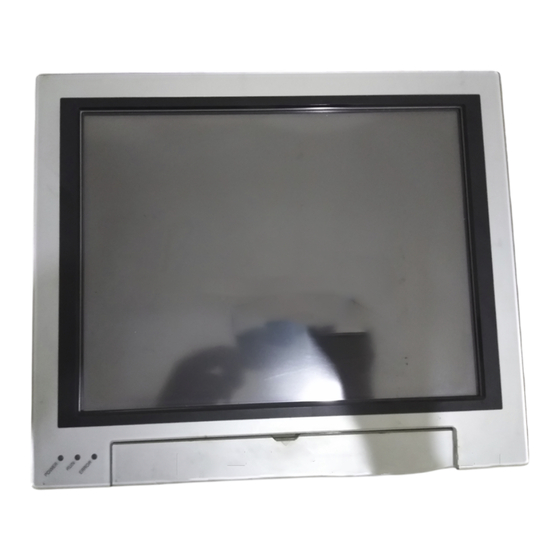
Component Names and Functions • LCD integrated type FZ4-600-10/FZ4-605-10/FZ4-H600-10/FZ4-H605-10 FZ4-700-10/FZ4-705-10/FZ4-H700-10/FZ4-H705-10 FZ4-1100-10/FZ4-1105-10/FZ4-H1100-10/FZ4-H1105-10 FZD-500-10/FZD-505-10 Left-side view Front view Right-side view RS-232C/RS-422 connector Power/ ground I/O connector terminal (control lines, data lines) Monitor connector (analog RGB) Ethernet connector Camera connector USB connector POWER LED RUN LED USB connector Touch pen (holder) -
Page 9: Parallel Interface
Parallel Interface NPN I/O type FZ4-600-10/FZ4-650-10/FZ4-H600-10/FZ4-H650-10/FZ4-700-10/FZ4-750-10/FZ4-H700-10 FZ4-H750-10/FZ4-1100-10/FZ4-1150-10/FZ4-H1100-10/FZ4-H1150-10/FZD-500-10/FZD-550-10 • Internal Specifications [Input] signals: STEP0/ENCTRIG_Z0, STEP1/ENCTRIG_Z1, [Input] signals: RESET, DI0 to DI7, DSA0, DSA1 ENCTRIG_A0 to 1, ENCTRIG_B0 to 1 Input voltage 12 to 24 V DC ±10 % Input voltage 12 to 24 V DC ±10 % ON current *1 5 mA min. - Page 10 Parallel Interface PNP I/O type FZ4-605-10/FZ4-655-10/FZ4-H605-10/FZ4-H655-10/FZ4-705-10/FZ4-755-10/FZ4-H705-10 FZ4-H755-10/FZ4-1105-10/FZ4-1155-10/FZ4-H1105-10/FZ4-H1155-10/FZD-505-10/FZD-555-10 • Internal Specifications [Input] signals: STEP0/ENCTRIG_Z0, STEP1/ENCTRIG_Z1, [Input] signals: RESET, DI0 to DI7, DSA0, DSA1 ENCTRIG_A0 to 1, ENCTRIG_B0 to 1 Input voltage 12 to 24 V DC ±10 % Input voltage 12 to 24 V DC ±10 % ON current *1 5 mA min.
-
Page 11: Serial Interface
• Recommended items Use a shielded cable. Manufacturer Model Pin numbers will depend on the external device being connected. Refer Plug OMRON Corporation XM3A-0921 to the manual for the personal computer or PLC being connected. Hood OMRON Corporation XM2S-0911 •... - Page 12 Mounting • LCD integrated type (Unit: mm) • Panel mounting Make a mount hole on the panel. Panel thickness range: 1.6 to 4.8 mm Panel material: Metal (iron, aluminum or stainless) * No burr allowed Insert the LCD integrated controller into the hole, from the front panel.
- Page 13 Controller External Dimensions • LCD integrated type FZ4-600-10/FZ4-605-10/FZ4-H600-10/FZ4-H605-10 FZ4-700-10/FZ4-705-10/FZ4-H700-10/FZ4-H705-10 FZ4-1100-10/FZ4-1105-10/FZ4-H1100-10/FZ4-H1105-10 FZD-500-10/FZD-505-10 (Unit: mm) 4-M3 Depth 6 12.8 28.4 • Box type FZ4-650-10/FZ4-655-10/FZ4-H650-10/FZ4-H655-10 FZ4-750-10/FZ4-755-10/FZ4-H750-10/FZ4-H755-10 FZ4-1150-10/FZ4-1155-10/FZ4-H1150-10/FZ4-H1155-10 FZD-550-10/FZD-555-10 (Unit: mm) 4-M4 Depth 6 4-M4 Depth 6 – 11.5 4-M4 Depth 6...
-
Page 14: Controller Specifications
Controller Specifications Operation LCD integrated type: Touch pen, mouse etc. BOX type: Mouse or similar device Serial communications RS-232C/422: 1 channel Network communications Ethernet 100BASE-TX/10BASE-T EtherNet/IP communication Use Ethernet port. (Exclude FZD) Transmission speed : 100Mbps(100BASE-TX) Parallel I/O 17 inputs (RESET, STEP0/ENCTRIG_Z0, STEP1/ENCTRIG_Z1, DSA0 to 1, ENCTRIG_A0 to 1, ENCTRIG_B0 to 1, DI0 to 7) 29 outputs (RUN/BUSY1, BUSY0, GATE0 to 1, OR0 to 1, READY0 to 1, ERROR, STGOUT0 to 3, DO0 to 15) Monitor interface...
Need help?
Do you have a question about the FZ4-60 10 Series and is the answer not in the manual?
Questions and answers