Table of Contents
Advertisement
Quick Links
A V T E C H
E L E C T R O S Y S T E M S
L T D .
N A N O S E C O N D
W A V E F O R M
E L E C T R O N I C S
S I N C E
1 9 7 5
info@avtechpulse.com
Tel: 888-670-8729 (USA & Canada) or +1-613-686-6675 (Intl)
BOX 5120, LCD MERIVALE
http://www.avtechpulse.com/
Fax: 800-561-1970 (USA & Canada) or +1-613-686-6679 (Intl)
OTTAWA, CANADA K2C3H5
INSTRUCTIONS
MODEL AVOZ-D6-B
1000 VOLT, 200 AMP
PULSE GENERATOR
WITH IEEE 488.2 AND RS-232 CONTROL
SERIAL NUMBER: ____________
Advertisement
Table of Contents

Subscribe to Our Youtube Channel
Related Manuals for AVTECH ELECTROSYSTEMS AVOZ-D6-B


Summary of Contents for AVTECH ELECTROSYSTEMS AVOZ-D6-B
- Page 1 Tel: 888-670-8729 (USA & Canada) or +1-613-686-6675 (Intl) BOX 5120, LCD MERIVALE http://www.avtechpulse.com/ Fax: 800-561-1970 (USA & Canada) or +1-613-686-6679 (Intl) OTTAWA, CANADA K2C3H5 INSTRUCTIONS MODEL AVOZ-D6-B 1000 VOLT, 200 AMP PULSE GENERATOR WITH IEEE 488.2 AND RS-232 CONTROL SERIAL NUMBER: ____________...
-
Page 2: Warranty
WARRANTY Avtech Electrosystems Ltd. warrants products of its manufacture to be free from defects in material and workmanship under conditions of normal use. If, within one year after delivery to the original owner, and after prepaid return by the original owner, this Avtech product is found to be defective, Avtech shall at its option repair or replace said defective item. -
Page 3: Table Of Contents
TABLE OF CONTENTS WARRANTY........................2 TECHNICAL SUPPORT....................2 TABLE OF CONTENTS....................3 INTRODUCTION.......................5 AVAILABLE OPTIONS.....................6 SPECIFICATIONS......................7 REGULATORY NOTES....................8 FCC PART 18.......................... 8 EC DECLARATION OF CONFORMITY..................8 DIRECTIVE 2011/65/EU (RoHS).....................9 DIRECTIVE 2002/96/EC (WEEE)....................9 FIRMWARE LICENSING.......................10 INSTALLATION......................11 VISUAL CHECK........................11 POWER RATINGS........................ 11 CONNECTION TO THE POWER SUPPLY................11 PROTECTION FROM ELECTRIC SHOCK................12 ENVIRONMENTAL CONDITIONS..................13 LABVIEW DRIVERS...................... - Page 4 PCB 104F - KEYPAD / DISPLAY BOARD, 2/3..............39 PCB 104F - KEYPAD / DISPLAY BOARD, 3/3..............40 MAIN WIRING - POSITIVE (-P) UNITS.................41 PERFORMANCE CHECK SHEET.................42 Manual Reference: /fileserver2/officefiles/instructword/avoz/AVOZ-D6-B,ed3.odt. Last modified June 5, 2019. Copyright © 2019 Avtech Electrosystems Ltd, All Rights Reserved.
-
Page 5: Introduction
(for instance, production testing of attenuators). The AVOZ-D6-B is capable of generating up to 1000V on each of its ten identical outputs, at repetition rates up to 500 Hz. The pulse width is variable from 1 us to 10 us, and the duty cycle may be as high as 0.05%. -
Page 6: Available Options
AVAILABLE OPTIONS -CK10 Option: Cable kit (ten RG-58C/U cables, 5ft/152cm) -OM10 Option: Output module, with ten input connectors and one output connector. -R5 Option: Rack-mount kit. -
Page 7: Specifications
SPECIFICATIONS Model AVOZ-D6-B Amplitude voltage (each output): 30 - 1000V current (sum of all outputs): 0 - 200A Minimum load impedance (parallel 5 Ω combination of loads on all outputs) Max. number of 50Ω loads (if outputs used separately): Load impedance notes:... -
Page 8: Regulatory Notes
This instrument does not normally require regular maintenance to minimize interference potential. However, if loose hardware or connectors are noted, they should be tightened. Contact Avtech (info@avtechpulse.com) if you require assistance. EC DECLARATION OF CONFORMITY Avtech Electrosystems Ltd. P.O. Box 5120, LCD Merivale Ottawa, Ontario Canada K2C 3H5 declare that this pulse generator meets the intent of Directive 2004/108/EG for Electromagnetic Compatibility. -
Page 9: Directive 2011/65/Eu (Rohs)
(also known as “RoHS Recast”). In addition, this declaration of conformity is issued under the sole responsibility of Avtech Electrosystems Ltd. Specifically, products manufactured do not contain the substances listed in the table below in concentrations greater than the listed maximum value. -
Page 10: Firmware Licensing
laws) on behalf of the customer, as provided for under Article 9 of Directive 2002/96/EC. Customers who have purchased Avtech equipment through local representatives should consult with the representative to determine who has responsibility for WEEE compliance. Normally, such responsibilities with lie with the representative, unless other arrangements (under Article 9) have been made. -
Page 11: Installation
INSTALLATION VISUAL CHECK After unpacking the instrument, examine to ensure that it has not been damaged in shipment. Visually inspect all connectors, knobs, liquid crystal displays (LCDs), and the handles. Confirm that a power cord, a GPIB cable, and two instrumentation manuals (this manual and the “Programming Manual for -B Instruments”) are with the instrument. -
Page 12: Protection From Electric Shock
Destination Region Description Option Manufacturer Part Number United Kingdom, Hong Kong, BS 1363, -AC00 Qualtek 370001-E01 Singapore, Malaysia 230V, 50 Hz AS 3112:2000, Australia, New Zealand -AC01 Qualtek 374003-A01 230-240V, 50 Hz Continental Europe, Korea, European CEE 7/7 -AC02 Qualtek 364002-D01 Indonesia, Russia “Schuko”... -
Page 13: Environmental Conditions
ENVIRONMENTAL CONDITIONS This instrument is intended for use under the following conditions: 1. indoor use; 2. altitude up to 2 000 m; 3. temperature 5 °C to 40 °C; 4. maximum relative humidity 80 % for temperatures up to 31 °C decreasing linearly to 50 % relative humidity at 40 °C;... -
Page 14: Fuses
FUSES This instrument contains four fuses. All are accessible from the rear-panel. Two protect the AC prime power input, and two protect the internal DC power supplies. The locations of the fuses on the rear panel are shown in the figure below: Fuses #1 and #2 Fuse #4 Fuse #3... -
Page 15: Dc Fuse Replacement
DC FUSE REPLACEMENT The DC fuses may be replaced by inserting the tip of a flat-head screwdriver into the fuse holder slot, and rotating the slot counter-clockwise. The fuse and its carrier will then pop out. FUSE RATINGS The following table lists the required fuses: Recommended Replacement Part Nominal Fuses... -
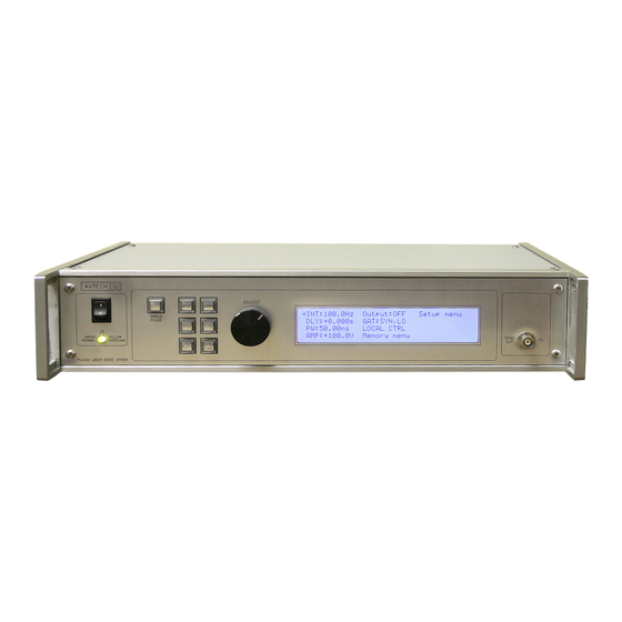
Page 16: Front Panel Controls
FRONT PANEL CONTROLS 1. POWER Switch . This is the main power switch. When turning the instrument on, there is normally a delay of 10 seconds before anything is shown on the main display, as the internal operating system boots up. If the main menu does not appear after 30 seconds, turn off the instrument and leave it off for at least 60 seconds before applying power again. - Page 17 detail. 5. KEYPAD . Control Name Function MOVE This moves the arrow pointer on the display. CHANGE This is used to enter the submenu, or to select the operating mode, pointed to by the arrow pointer. ×10 If one of the adjustable numeric parameters is displayed, this increases the setting by a factor of ten.
-
Page 18: Rear Panel Controls
REAR PANEL CONTROLS GATE TRIG RS-232 GPIB Note: some connectors may be in different positions than shown above, depending on the exact combination of options ordered. 1. AC POWER INPUT . An IEC-320 C14 three-pronged recessed male socket is provided on the back panel for AC power connection to the instrument. One end of the detachable power cord that is supplied with the instrument plugs into this socket. - Page 19 When triggering externally, the instrument can be set such that the output pulse width tracks the pulse width on this input, or the output pulse width can be set independently. 6. GPIB Connector . A standard GPIB cable can be attached to this connector to allow the instrument to be computer-controlled.
-
Page 20: General Information
GENERAL INFORMATION BASIC PULSE CONTROL This instrument can be triggered by its own internal clock or by an external TTL trigger signal. In either case, two output channels respond to the trigger: OUT and SYNC. The OUT channel is the signal that is applied to the load. Its amplitude and pulse width are variable. - Page 21 > 50 ns TRIG TTL LEVELS (external input) (0V and 3V-5V) PROPAGATION DELAY (FIXED) 100 ns, FIXED SYNC OUT 3V, FIXED DELAY > 0 PULSE WIDTH AMPLITUDE, VARIABLE MAIN OUTPUT Figure C As before, if the delay is negative, the order of the SYNC and OUT pulses is reversed. The last figure illustrates the relationship between the signal when an external TTL-level trigger is used in the PW mode.
-
Page 22: Trigger Modes
TRIGGER MODES This instrument has four trigger modes: Internal Trigger: the instrument controls the trigger frequency, and generates the clock internally. External Trigger: the instrument is triggered by an external TTL-level clock on the back-panel TRIG connector. Manual Trigger: the instrument is triggered by the front-panel “SINGLE PULSE” pushbutton. -
Page 23: Amplitude Decay Time
THE LOAD AND OUTPUT MODULE The AVOZ-D6-B has ten identical outputs. These outputs can either be combined to drive a single low-impedance (5 Ohms) load, or can be used separately to drive multiple 50 Ohm loads simultaneously. -
Page 24: Preventing Output Stage Failure
AVOZ-D6-B REAL-TIME MAINFRAME SCOPE OSCILLOSCOPE PROBE OUT CONNECTOR #1 CHANNEL A OUT CONNECTOR #2 50 Ω, 10 W OUT CONNECTOR #10 POWER CHANNEL B To 8 other 50 Ω, 50 Ohm loads. TRIG SYNC 10 W INPUT OUTPUT PREVENTING OUTPUT STAGE FAILURE The output stage is protected against overload conditions by an overload circuit and fuses on the main frame back panel. -
Page 25: Operational Check
4. Turn on the AVOZ-D6-B. The main menu will appear on the LCD. 5. To set the AVOZ-D6-B to trigger from the internal clock at a PRF of 10 Hz: a) The arrow pointer should be pointing at the frequency menu item. If it is not, press the MOVE button until it is. - Page 26 c) The arrow pointer should be pointing at the “Internal” choice. If it is not, press MOVE until it is. d) Press CHANGE to return to the main menu. 6. To set the delay to 1 us: a) Press the MOVE button until the arrow pointer is pointing at the delay menu item.
- Page 27 a) Press the MOVE button until the arrow pointer is pointing at the amplitude menu item. b) Press the CHANGE button. The amplitude submenu will appear. Rotate the ADJUST knob until the amplitude is set at +500V (or -500V for "-N" instruments).
-
Page 28: Programming Your Pulse Generator
PROGRAMMING YOUR PULSE GENERATOR KEY PROGRAMMING COMMANDS The “Programming Manual for -B Instruments” describes in detail how to connect the pulse generator to your computer, and the programming commands themselves. A large number of commands are available; however, normally you will only need a few of these. -
Page 29: All Programming Commands
ALL PROGRAMMING COMMANDS For more advanced programmers, a complete list of the available commands is given below. These commands are described in detail in the “Programming Manual for -B Instruments”. (Note: this manual also includes some commands that are not implemented in this instrument. - Page 30 :SOURce INTernal | EXTernal | MANual | HOLD | IMMediate *CLS [no query form] *ESE <numeric value> *ESR? [query only] *IDN? [query only] *OPC *SAV 0 | 1 | 2 | 3 [no query form] *RCL 0 | 1 | 2 | 3 [no query form] *RST [no query form]...
-
Page 31: Mechanical Information
MECHANICAL INFORMATION TOP COVER REMOVAL If necessary, the interior of the instrument may be accessed by removing the four Phillips screws on the top panel. With the four screws removed, the top cover may be slid back (and off). Always disconnect the power cord and allow the instrument to sit unpowered for 10 minutes before opening the instrument. -
Page 32: Maintenance
MAINTENANCE REGULAR MAINTENANCE This instrument does not require any regular maintenance. On occasion, one or more of the four rear-panel fuses may require replacement. All fuses can be accessed from the rear panel. See the “FUSES” section for details. CLEANING If desired, the interior of the instrument may be cleaned using compressed air to dislodge any accumulated dust. -
Page 33: Wiring Diagrams
WIRING DIAGRAMS WIRING OF AC POWER M a ins circuits - ha z ard ou s live . A3 - BLACK Do not attem pt any repairs on this instrument POWER SWITCH SW325-ND (CW INDUSTRIES G RS-4022-0013) bey ond the fuse replacement procedures described in the m anual. -
Page 34: Wiring Of Dc Power
WIRING OF DC POWER M OUNT WIT H 1/2" ST ANDO FFS P1, N1 = 15000uF, 35V x 2 R1,R2 (O N BOT T OM ): 1.8K O Y CHS GND G RN T O AC/DC CONVERT ER PCB 179B, TRIM MED EXT RA LINES O N HIG H-PO WER ALL UNIT S... -
Page 35: Pcb 158R4 - Low Voltage Power Supply
PCB 158R4 - LOW VOLTAGE POWER SUPPLY... -
Page 36: Pcb 197G - High-Voltage Power Supply
PCB 197G - HIGH-VOLTAGE POWER SUPPLY... -
Page 37: Pcb 183A-S And 183A-P Capacitor Banks
PCB 183A-S AND 183A-P CAPACITOR BANKS 183A-S (SERIES CAPACIT OR BANK) 7 2 00 K -ND, Mfg . 7 2 0 0, 4-4 0 th read stando ff 3 /8" HV + GN D 7 2 00 K -ND, Mfg . 7 2 0 0, 4-4 0 th read stando ff 3 /8" X1 1 7 2 00 K -ND, Mfg . -
Page 38: Pcb 104F - Keypad / Display Board, 1/3
PCB 104F - KEYPAD / DISPLAY BOARD, 1/3 Amp 5 4 9 9 9 1 0 -1 , 1 0 p in strai g h t h ead er LC D-BU TT LC D-BU TT. SCH SD A SD A SC L SC L GN D... -
Page 39: Pcb 104F - Keypad / Display Board, 2/3
PCB 104F - KEYPAD / DISPLAY BOARD, 2/3 U4 A VC C C1 0 VC C BU T1 VC C 2 . 2 u F C1 5 C1 3 0 . 1 u F 0 . 1 u F 0 . 1 u F 0 . -
Page 40: Pcb 104F - Keypad / Display Board, 3/3
PCB 104F - KEYPAD / DISPLAY BOARD, 3/3 VC C VC C 0 . 1 u F 2 . 2 u F GN D VC C VC C VC C SD A SD A SC L SC L GN D PA D3 PA D4 PC F8 5 7 4 AN (MU ST HA VE "A"... -
Page 41: Main Wiring - Positive (-P) Units
MAIN WIRING - POSITIVE (-P) UNITS +15V NSY FOR BO T H: USE 1/2" ST ANDOFFS P1-P3: 220uF, 400V VPRF N1-N3: 220uF, 400V (O PPO SIT E O F SILKSCREEN +/-) VSPARE R1-R6 (BOT , UNDER CAPS): 150K OY PCB 183A-S PCB 183A-S SYNC CONN1... -
Page 42: Performance Check Sheet
PERFORMANCE CHECK SHEET...
Need help?
Do you have a question about the AVOZ-D6-B and is the answer not in the manual?
Questions and answers