Table of Contents
Advertisement
Quick Links
P.O. BOX 265
OGDENSBURG, NY
U.S.A. 13669-0265
A V T E C H
TEL: 888-670-8729 (USA & Canada) or +1-613-686-6675 (Intl)
FAX: 800-561-1970 (USA & Canada) or +1-613-686-6679 (Intl)
info@avtechpulse.com
INSTRUCTIONS
MODEL AVMP-2-B
0 TO 10 VOLTS, 100 ps RISE TIME
HIGH PERFORMANCE PULSE GENERATOR
WITH IEEE 488.2 AND RS-232 CONTROL
SERIAL NUMBER: ____________
E L E C T R O S Y S T E M S
N A N O S E C O N D
W A V E F O R M
S I N C E
-
http://www.avtechpulse.com/
E L E C T R O N I C S
1 9 7 5
BOX 5120, LCD MERIVALE
X
OTTAWA, ONTARIO
CANADA
L T D .
K2C 3H5
Advertisement
Table of Contents

Related Manuals for AVTECH ELECTROSYSTEMS AVMP-2-B


Summary of Contents for AVTECH ELECTROSYSTEMS AVMP-2-B
- Page 1 FAX: 800-561-1970 (USA & Canada) or +1-613-686-6679 (Intl) OTTAWA, ONTARIO U.S.A. 13669-0265 CANADA K2C 3H5 info@avtechpulse.com http://www.avtechpulse.com/ INSTRUCTIONS MODEL AVMP-2-B 0 TO 10 VOLTS, 100 ps RISE TIME HIGH PERFORMANCE PULSE GENERATOR WITH IEEE 488.2 AND RS-232 CONTROL SERIAL NUMBER: ____________...
-
Page 2: Warranty
WARRANTY Avtech Electrosystems Ltd. warrants products of its manufacture to be free from defects in material and workmanship under conditions of normal use. If, within one year after delivery to the original owner, and after prepaid return by the original owner, this Avtech product is found to be defective, Avtech shall at its option repair or replace said defective item. -
Page 3: Table Of Contents
TABLE OF CONTENTS WARRANTY........................2 TECHNICAL SUPPORT....................2 TABLE OF CONTENTS....................3 INTRODUCTION.......................5 AVAILABLE OPTIONS......................5 SPECIFICATIONS......................6 REGULATORY NOTES....................7 FCC PART 18.......................... 7 EC DECLARATION OF CONFORMITY..................7 DIRECTIVE 2002/95/EC (RoHS).....................8 DIRECTIVE 2002/96/EC (WEEE)....................8 AC POWER SUPPLY REGULATORY NOTES...............9 INSTALLATION......................10 VISUAL CHECK........................10 POWER RATINGS........................ 10 CONNECTION TO THE POWER SUPPLY................10 PROTECTION FROM ELECTRIC SHOCK................11 ENVIRONMENTAL CONDITIONS..................12... - Page 4 PCB 104E - KEYPAD / DISPLAY BOARD, 2/3..............39 PCB 104E - KEYPAD / DISPLAY BOARD, 3/3..............40 MAIN WIRING - NEGATIVE UNITS..................41 PERFORMANCE CHECKSHEET..................42 Manual Reference: /fileserver2/officefiles/instructword/avmp/AVMP-2-B,ed4.odt. Last modified November 22, 2012. Copyright © 2012 Avtech Electrosystems Ltd, All Rights Reserved.
-
Page 5: Introduction
"-N" model suffix can generate 0 to -10V. Instruments with the "-PN" suffix can generate both polarities. The AVMP-2-B is a highly flexible instrument. Aside from the internal trigger source, it can also be triggered or gated by external TTL-level signals. A front-panel pushbutton or a computer command can also be used to trigger the instrument. -
Page 6: Specifications
SPECIFICATIONS Model: AVMP-2-B Amplitude : (50Ω load) 0 - 10 Volts Pulse width (FWHM): 5 ns - 100 ns Maximum PRF: 1 MHz Maximum duty cycle: Rise time (20%-80%): ≤ 100 ps Fall time (80%-20%): ≤ 135 ps Required load impedance:... -
Page 7: Regulatory Notes
This instrument does not normally require regular maintenance to minimize interference potential. However, if loose hardware or connectors are noted, they should be tightened. Contact Avtech (info@avtechpulse.com) if you require assistance. EC DECLARATION OF CONFORMITY Avtech Electrosystems Ltd. P.O. Box 5120, LCD Merivale Ottawa, Ontario Canada K2C 3H4 declare that this pulse generator meets the intent of Directive 2004/108/EG for Electromagnetic Compatibility. -
Page 8: Directive 2002/95/Ec (Rohs)
and that this pulse generator meets the intent of the Low Voltage Directive 72/23/EEC as amended by 93/68/EEC. Compliance pertains to the following specifications as listed in the official Journal of the European Communities: EN 61010-1:2001 Safety requirements for electrical equipment for measurement, control, and laboratory use DIRECTIVE 2002/95/EC (RoHS) This instrument is exempt from Directive 2002/95/EC of the European Parliament and... -
Page 9: Ac Power Supply Regulatory Notes
AC POWER SUPPLY REGULATORY NOTES This instrument converts the AC input power to the +24V DC voltage that powers the internal circuitry of this instrument using a Tamura AAD130SD-60-A switching power supply. According to the manufacturer, the Tamura AAD130SD-60-A has the following certifications: UL60950-1 IEC60950 -1... -
Page 10: Installation
INSTALLATION VISUAL CHECK After unpacking the instrument, examine to ensure that it has not been damaged in shipment. Visually inspect all connectors, knobs, liquid crystal displays (LCDs), and the handles. Confirm that a power cord, a GPIB cable, and two instrumentation manuals (this manual and the “Programming Manual for -B Instruments”) are with the instrument. -
Page 11: Protection From Electric Shock
Destination Region Description Option Manufacturer Part Number United Kingdom, Hong Kong, BS 1363, -AC00 Qualtek 370001-E01 Singapore, Malaysia 230V, 50 Hz AS 3112:2000, Australia, New Zealand -AC01 Qualtek 374003-A01 230-240V, 50 Hz Continental Europe, Korea, European CEE 7/7 -AC02 Qualtek 364002-D01 Indonesia, Russia “Schuko”... -
Page 12: Environmental Conditions
ENVIRONMENTAL CONDITIONS This instrument is intended for use under the following conditions: 1. indoor use; 2. altitude up to 2 000 m; 3. temperature 5 °C to 40 °C; 4. maximum relative humidity 80 % for temperatures up to 31 °C decreasing linearly to 50 % relative humidity at 40 °C;... -
Page 13: Fuses
FUSES This instrument contains four fuses. All are accessible from the rear-panel. Two protect the AC prime power input, and two protect the internal DC power supplies. The locations of the fuses on the rear panel are shown in the figure below: Fuses #1 and #2 Fuse #4 Fuse #3... -
Page 14: Dc Fuse Replacement
The DC fuses may be replaced by inserting the tip of a flat-head screwdriver into the fuse holder slot, and rotating the slot counter-clockwise. The fuse and its carrier will then pop out. FUSE RATINGS The following table lists the required fuses for the AVMP-2-B: Recommended Replacement Part Nominal Fuses... -
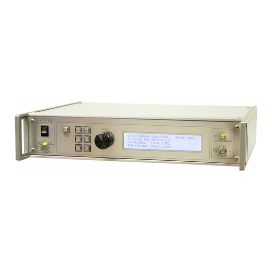
Page 15: Front Panel Controls
FRONT PANEL CONTROLS 1. POWER Switch . This is the main power switch. When turning the instrument on, there may be a delay of several seconds before the instrument appears to respond. 2. OVERLOAD Indicator . When the instrument is powered, this indicator is normally green, indicating normal operation. - Page 16 6. KEYPAD . Control Name Function MOVE This moves the arrow pointer on the display. CHANGE This is used to enter the submenu, or to select the operating mode, pointed to by the arrow pointer. ×10 If one of the adjustable numeric parameters is displayed, this increases the setting by a factor of ten.
-
Page 17: Rear Panel Controls
REAR PANEL CONTROLS DC OFFSET GRN=LNK GATE YEL=ACT TRIG INT EXT RS-232 GPIB Some connectors may be in different positions than those shown above, depending on the exact combination of options ordered. 1. AC POWER INPUT . An IEC-320 C14 three-pronged recessed male socket is provided on the back panel for AC power connection to the instrument. - Page 18 6. GPIB Connector . A standard GPIB cable can be attached to this connector to allow the instrument to be computer-controlled. See the “Programming Manual for -B Instruments” for more details on GPIB control. 7. RS-232 Connector. A standard serial cable with a 25-pin male connector can be attached to this connector to allow the instrument to be computer-controlled.
- Page 19 in the EXT position. DC OFFSET A Connector. (Optional feature. Present on units with the -EO option only). If the DC OFFSET INT/EXT switch is in the EXT position, a 0 to +10V control voltage applied to this input will vary the output DC offset over the range of -5V to +5V, approximately.
-
Page 20: General Information
GENERAL INFORMATION BASIC PULSE CONTROL This instrument can be triggered by its own internal clock or by an external TTL trigger signal. In either case, two output channels respond to the trigger: OUT and SYNC. • OUT. This is the main output. •... -
Page 21: Trigger Modes
The next figure illustrates the relationship between the signal when an external TTL- level trigger is used: > 50 ns TRIG TTL LEVELS (external input) (0V and 3V-5V) PROPAGATION DELAY (FIXED) 100 ns, FIXED SYNC OUT 3V, FIXED DELAY > 0 PULSE WIDTH AMPLITUDE, VARIABLE... -
Page 22: Gating Modes
GATING MODES Triggering can be suppressed by a TTL-level signal on the rear-panel GATE connector. The instrument can be set to stop triggering when this input high or low, using the front- panel gate menu or the appropriate programming commands. When gated, the output will complete the full pulse width if the output is high, and then stop triggering. -
Page 23: Optional Features
OPTIONAL FEATURES RACK MOUNTING, "-R5" OPTION A rack mounting kit is available. The "-R5" rack mount kit may be installed after first removing the one Phillips screw on the side panel adjacent to the front handle. DC OFFSET, "-OT" OPTION This option adds an internally-generated 0 to ±5V DC offset to the main output. -
Page 24: Protecting Your Instrument
PROTECTING YOUR INSTRUMENT TURN OFF INSTRUMENT WHEN NOT IN USE The lifetime of the switching elements in the pulse generator module is proportional to the running time of the instrument. For this reason the prime power to the instrument should be turned off when the instrument is not in use. In the case of failure, the switching elements are easily replaced following the procedure described in a following section. -
Page 25: Operational Check
OPERATIONAL CHECK This section describes a sequence to confirm the basic operation of the instrument. It should be performed after receiving the instrument. It is a useful learning exercise as well. Before proceeding with this procedure, finish reading this instruction manual thoroughly. - Page 26 2. Turn on the AVMP-2-B. The main menu will appear on the LCD. 3. To set the AVMP-2-B to trigger from the internal clock at a PRF of 10 kHz: a) The arrow pointer should be pointing at the frequency menu item. If it is not, press the MOVE button until it is.
- Page 27 7. To enable the output: a) Press the MOVE button until the arrow pointer is pointing at the output menu item. b) Press the CHANGE button. The output submenu will appear. c) Press MOVE until the arrow pointer is pointing at the “ON” choice. d) Press CHANGE to return to the main menu.
- Page 28 This completes the operational check.
-
Page 29: Programming Your Pulse Generator
PROGRAMMING YOUR PULSE GENERATOR KEY PROGRAMMING COMMANDS The “OP1B Interface Programming Manual” describes in detail how to connect the pulse generator to your computer, and the programming commands themselves. A large number of commands are available; however, normally you will only need a few of these. -
Page 30: All Programming Commands
ALL PROGRAMMING COMMANDS For more advanced programmers, a complete list of the available commands is given below. These commands are described in detail in the “OP1B Interface Programming Manual”. (Note: this manual also includes some commands that are not implemented in this instrument. - Page 31 :[TYPE] EVEN | ODD | NONE :SBITS 1 | 2 :ERRor :[NEXT]? [query only] :COUNT? [query only] :VERSion? [query only] TRIGger: :SOURce INTernal | EXTernal | MANual | HOLD | IMMediate *CLS [no query form] *ESE <numeric value> *ESR? [query only] *IDN? [query only] *OPC...
-
Page 32: Mechanical Information
MECHANICAL INFORMATION TOP COVER REMOVAL If necessary, the interior of the instrument may be accessed by removing the four Phillips screws on the top panel. With the four screws removed, the top cover may be slid back (and off). Always disconnect the power cord and allow the instrument to sit unpowered for 10 minutes before opening the instrument. -
Page 33: Maintenance
MAINTENANCE REGULAR MAINTENANCE This instrument does not require any regular maintenance. On occasion, one or more of the four rear-panel fuses may require replacement. All fuses can be accessed from the rear panel. See the “FUSES” section for details. CLEANING If desired, the interior of the instrument may be cleaned using compressed air to dislodge any accumulated dust. -
Page 34: Wiring Diagrams
WIRING DIAGRAMS WIRING OF AC POWER M a in s c ir c u i ts - h a z a r d o u s liv e . D o n o t a tte m p t a n y r e p a i r s o n th is in s t r u m e n t b e y o n d t h e fu s e r e p l a c e m e n t p r o c e d u r e s d e s c r i b e d in th e m a n u a l . -
Page 35: Pcb 158N - Low Voltage Power Supply, 1/3
PCB 158N - LOW VOLTAGE POWER SUPPLY, 1/3 p c b 1 5 8 N _ o v p p c b 1 5 8 N _ o v p . s c h + 1 5 V + 1 5 V + 1 5 V B U + B U +... -
Page 36: Pcb 158N - Low Voltage Power Supply, 2/3
PCB 158N - LOW VOLTAGE POWER SUPPLY, 2/3 8 3 0 8 3 5 F U S E H O L D E R 6 4 0 4 4 5 - 6 T P 6 T P 3 T E S T - L O O P T E S T - L O O P S 1 A S 1 B , O R D C... -
Page 37: Pcb 158N - Low Voltage Power Supply, 3/3
PCB 158N - LOW VOLTAGE POWER SUPPLY, 3/3 R 2 1 1 . 5 K o r 1 . 8 K O Y C A P B A N K R 2 6 1 5 K C 2 3 1 0 0 0 u F , 3 5 V ( P 5 1 6 9 - N D ) L 6 2 7 1 1 H V W A R N I N G R 1 7... -
Page 38: Pcb 104E - Keypad / Display Board, 1/3
PCB 104E - KEYPAD / DISPLAY BOARD, 1/3 A H E 1 0 G - N D , M f g 4 9 9 9 1 0 - 1 , 1 0 p i n s t r a i g h t h e a d e r L C D - B U T T L C D - B U T T . -
Page 39: Pcb 104E - Keypad / Display Board, 2/3
PCB 104E - KEYPAD / DISPLAY BOARD, 2/3 U 4 A V C C C 1 0 V C C B U T 1 V C C 2 . 2 u F C 1 5 C 1 3 1 5 K V C C M M 7 4 H C 1 4 N 0 . -
Page 40: Pcb 104E - Keypad / Display Board, 3/3
PCB 104E - KEYPAD / DISPLAY BOARD, 3/3 V C C V C C 0 . 1 u F 2 . 2 u F G N D V C C V C C V C C S D A S D A S C L S C L I N T... -
Page 41: Main Wiring - Negative Units
MAIN WIRING - NEGATIVE UNITS - 1 5 V P G - N + 2 4 V , N O O L O + 2 4 V - 1 5 V G N D , N O O L O G N D G N D N / C... -
Page 42: Performance Checksheet
PERFORMANCE CHECKSHEET...
Need help?
Do you have a question about the AVMP-2-B and is the answer not in the manual?
Questions and answers