Table of Contents
Advertisement
Quick Links
A V T E C H
E L E C T R O S Y S T E M S
L T D .
N A N O S E C O N D
W A V E F O R M
E L E C T R O N I C S
S I N C E
1 9 7 5
info@avtechpulse.com
Tel: 888-670-8729 (USA & Canada)
BOX 5120, LCD MERIVALE
http://www.avtechpulse.com/
or +1-613-686-6675 (Worldwide)
OTTAWA, CANADA K2C3H5
INSTRUCTIONS
MODEL AVRZ-5W-B
500 VOLTS INTO 50 Ω, 15 ns TO 10 us
HIGH-VOLTAGE, HIGH-SPEED PULSE GENERATOR
WITH IEEE 488.2 / RS-232 / ETHERNET CONTROL
SERIAL NUMBER:
14398
Advertisement
Table of Contents

Subscribe to Our Youtube Channel
Related Manuals for AVTECH ELECTROSYSTEMS AVRZ-5W-B


Summary of Contents for AVTECH ELECTROSYSTEMS AVRZ-5W-B
- Page 1 Tel: 888-670-8729 (USA & Canada) BOX 5120, LCD MERIVALE http://www.avtechpulse.com/ or +1-613-686-6675 (Worldwide) OTTAWA, CANADA K2C3H5 INSTRUCTIONS MODEL AVRZ-5W-B 500 VOLTS INTO 50 Ω, 15 ns TO 10 us HIGH-VOLTAGE, HIGH-SPEED PULSE GENERATOR WITH IEEE 488.2 / RS-232 / ETHERNET CONTROL SERIAL NUMBER: 14398...
-
Page 2: Warranty
WARRANTY Avtech Electrosystems Ltd. warrants products of its manufacture to be free from defects in material and workmanship under conditions of normal use. If, within one year after delivery to the original owner, and after prepaid return by the original owner, this Avtech product is found to be defective, Avtech shall at its option repair or replace said defective item. -
Page 3: Table Of Contents
TABLE OF CONTENTS WARRANTY........................2 TECHNICAL SUPPORT....................2 TABLE OF CONTENTS....................3 INTRODUCTION......................6 HIGH-VOLTAGE PRECAUTIONS..................7 SPECIFICATIONS......................8 REGULATORY NOTES....................9 FCC PART 18.......................... 9 EC DECLARATION OF CONFORMITY..................9 DIRECTIVE 2011/65/EU (RoHS)...................10 DIRECTIVE 2002/96/EC (WEEE)..................10 FIRMWARE LICENSING.......................11 INSTALLATION......................12 VISUAL CHECK........................12 POWER RATINGS........................ 12 CONNECTION TO THE POWER SUPPLY................12 PROTECTION FROM ELECTRIC SHOCK................13 ENVIRONMENTAL CONDITIONS..................14... - Page 4 -OS OFFSET OPTION......................26 -LVA INTERNAL ATTENUATORS OPTION.................26 -SIL SAFETY INTERLOCK OPTION..................26 -RL50 RESISTOR OPTION....................26 MINIMIZING WAVEFORM DISTORTIONS..............27 USE 50 OHM TRANSMISSION LINES.................27 USE LOW-INDUCTANCE LOADS..................27 “BACK-PORCH” TRANSIENT....................27 PROTECTING YOUR INSTRUMENT................28 TURN OFF INSTRUMENT WHEN NOT IN USE..............28 DO NOT EXCEED 5 kHz.......................28 USE A 50 OHM LOAD......................28 OPERATIONAL CHECK....................29 PROGRAMMING YOUR PULSE GENERATOR............32...
- Page 5 PERFORMANCE CHECK SHEET................47 Manual Reference: /fileserver1/officefiles/instructword/avrz/AVRZ-5W-B,ed41.odt. Last modified December 14, 2023. Copyright © 2023 Avtech Electrosystems Ltd, All Rights Reserved.
-
Page 6: Introduction
INTRODUCTION The AVRZ-5 models are high performance, GPIB and RS232-equipped instruments capable of generating up to +500V into 50Ω loads at repetition rates up to 5 kHz. Note: a non-inductive 50Ω load is required for proper operation. The instrument may be damaged if a non-inductive 50Ω load is not attached. Such damage is not covered by the warranty. -
Page 7: High-Voltage Precautions
HIGH-VOLTAGE PRECAUTIONS CAUTION: This instrument provides output voltages as high as 500 Volts under normal operating conditions, and generates > 1000V internally, so extreme caution must be employed when using this instrument. The instrument should only be used by individuals who are thoroughly skilled in high voltage laboratory techniques. The following precautions should always be observed: 1. -
Page 8: Specifications
SPECIFICATIONS Model: AVRZ-5W-B Amplitude Standard: ≤ 50 to 500 Volts. With -LVA option : ≤ 0.1 to 500 Volts Polarity: Positive Output impedance during pulse 50 Ω Required load impedance 50 Ω Rise time (20% - 80%) 0 to +250V: ≤ 4.5 ns (6.5 ns for units with -LVA option) +250 to +500V: ≤... -
Page 9: Regulatory Notes
This instrument does not normally require regular maintenance to minimize interference potential. However, if loose hardware or connectors are noted, they should be tightened. Contact Avtech (info@avtechpulse.com) if you require assistance. EC DECLARATION OF CONFORMITY Avtech Electrosystems Ltd. P.O. Box 5120, LCD Merivale Ottawa, Ontario Canada K2C 3H5 declare that this pulse generator meets the intent of Directive 2014/30/EU for Electromagnetic Compatibility. -
Page 10: Directive 2011/65/Eu (Rohs)
(also known as “RoHS Recast”). In addition, this declaration of conformity is issued under the sole responsibility of Avtech Electrosystems Ltd. Specifically, products manufactured do not contain the substances listed in the table below in concentrations greater than the listed maximum value. -
Page 11: Firmware Licensing
laws) on behalf of the customer, as provided for under Article 9 of Directive 2002/96/EC. Customers who have purchased Avtech equipment through local representatives should consult with the representative to determine who has responsibility for WEEE compliance. Normally, such responsibilities with lie with the representative, unless other arrangements (under Article 9) have been made. -
Page 12: Installation
INSTALLATION VISUAL CHECK After unpacking the instrument, examine to ensure that it has not been damaged in shipment. Visually inspect all connectors, knobs, liquid crystal displays (LCDs), and the handles. Confirm that a power cord, a GPIB cable, and two instrumentation manuals (this manual and the “Programming Manual for -B Instruments”) are with the instrument. -
Page 13: Protection From Electric Shock
Destination Region Description Option Manufacturer Part Number United Kingdom, Hong Kong, BS 1363, -AC00 Qualtek 370001-E01 Singapore, Malaysia 230V, 50 Hz AS 3112:2000, Australia, New Zealand -AC01 Qualtek 374003-A01 230-240V, 50 Hz Continental Europe, Korea, European CEE 7/7 -AC02 Qualtek 364002-D01 Indonesia, Russia “Schuko”... -
Page 14: Environmental Conditions
ENVIRONMENTAL CONDITIONS This instrument is intended for use under the following conditions: 1. indoor use; 2. altitude up to 2 000 m; 3. temperature 5 °C to 40 °C; 4. maximum relative humidity 80 % for temperatures up to 31 °C decreasing linearly to 50 % relative humidity at 40 °C;... -
Page 15: Fuses
FUSES This instrument contains four fuses. All are accessible from the rear-panel. Two protect the AC prime power input, and two protect the internal DC power supplies. The locations of the fuses on the rear panel are shown in the figure below: Fuses #1 and #2 Fuse #4 Fuse #3... -
Page 16: Dc Fuse Replacement
DC FUSE REPLACEMENT The DC fuses may be replaced by inserting the tip of a flat-head screwdriver into the fuse holder slot, and rotating the slot counter-clockwise. The fuse and its carrier will then pop out. FUSE RATINGS The following table lists the required fuses: Recommended Replacement Part Nominal Fuses... -
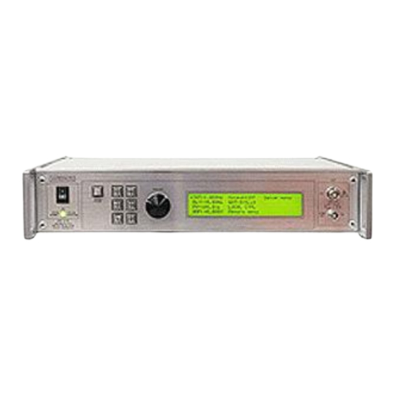
Page 17: Front Panel Controls
FRONT PANEL CONTROLS 1. POWER Switch . This is the main power switch. When turning the instrument on, there is normally a delay of 10 seconds before anything is shown on the main display, as the internal operating system boots up. 2. - Page 18 4. SYNC OUT . This connector supplies a SYNC output that can be used to trigger other equipment, particularly oscilloscopes. This signal leads (or lags) the main output by a duration set by the "DELAY" controls and has an approximate amplitude of +3 Volts to R >...
-
Page 19: Rear Panel Controls
REAR PANEL CONTROLS GATE AMP / LOCK TRIG RS-232 GPIB Note: some connectors may be in different positions than shown above, depending on the exact combination of options ordered. 1. AC POWER INPUT . An IEC-320 C14 three-pronged recessed male socket is provided on the back panel for AC power connection to the instrument. - Page 20 6. GPIB Connector . A standard GPIB cable can be attached to this connector to allow the instrument to be computer-controlled. See the “Programming Manual for -B Instruments” for more details on GPIB control. 7. RS-232 Connector. A standard serial cable with a 25-pin male connector can be attached to this connector to allow the instrument to be computer-controlled.
-
Page 21: General Information
GENERAL INFORMATION BASIC PULSE CONTROL This instrument can be triggered by its own internal clock or by an external TTL trigger signal. In either case, two output channels respond to the trigger: OUT and SYNC. The OUT channel is the signal that is applied to the load. Its amplitude and pulse width are variable. -
Page 22: Trigger Modes
> 50 ns TRIG TTL LEVELS (external input) (0V and 3V-5V) PROPAGATION DELAY (FIXED) 100 ns, FIXED SYNC OUT 3V, FIXED DELAY > 0 PULSE WIDTH AMPLITUDE, VARIABLE MAIN OUTPUT Figure C As before, if the delay is negative, the order of the SYNC and OUT pulses is reversed. The delay, pulse width, and frequency (when in the internal mode), of the OUT pulse can be varied with front panel controls or via the GPIB or RS-232 computer interfaces. -
Page 23: Gating Modes
GATING MODES Triggering can be suppressed by a TTL-level signal on the rear-panel GATE connector. The instrument can be set to stop triggering when this input high or low, using the front- panel gate menu or the appropriate programming commands. The timing nature (synchronous versus asynchronous) is adjustable on some instruments. -
Page 24: Negative Pulse Generation
NEGATIVE PULSE GENERATION -INV OPTION The AVRZ-5W-B mainframe normally generate positive amplitudes in the range of 0 to +500V. Negative pulses can be generated using the -INV option inverting transformer accessory. (This accessory can also be ordered separately as Model AVX-R5. See http://www.avtechpulse.com/transformer/avx-r5... -
Page 25: Pn Option
100 V/div, 2 us/div. (Rise and fall times measured at 20%-80%) -PN OPTION Instruments with the -PN option contain a relay-switched inverting transformer inside the instrument. The performance is similar to that described above. The polarity is controlled by setting the amplitude to a negative value from the front panel, or by computer command (for example: volt -400). -
Page 26: Other Options
OTHER OPTIONS -OS OFFSET OPTION This option provides a special-purpose bias-tee accessory module (model AVX-TG), which can be used to apply a 0 to +/- 5V DC offset to the output of the instrument. This bias-tee can be placed before or after any installed attenuators, if required. The externally-generated DC bias is applied to a solder terminal. -
Page 27: Minimizing Waveform Distortions
“BACK-PORCH” TRANSIENT A “back-porch” transient is present on the falling edge of the AVRZ-5W-B output. This is normal, and unavoidable. A typical waveform is shown below: This transient should be less than 20% of the peak amplitude, and less than 100 ns in... -
Page 28: Protecting Your Instrument
PROTECTING YOUR INSTRUMENT TURN OFF INSTRUMENT WHEN NOT IN USE The lifetime of the switching elements in the pulse generator module is proportional to the running time of the instrument. For this reason the prime power to the instrument should be turned off when the instrument is not in use. In the case of failure, the switching elements are easily replaced following the procedure described in a following section. -
Page 29: Operational Check
2. For units with the -SIL option, ensure that the signal pin of the rear-panel LOCK BNC connector is shorted to chassis ground. (The connector shield is connected to chassis ground.) 3. Turn on the AVRZ-5W-B. The main menu will appear on the LCD. - Page 30 4. To set the AVRZ-5W-B to trigger from the internal clock at a PRF of 100 Hz: a) The arrow pointer should be pointing at the frequency menu item. If it is not, press the MOVE button until it is.
- Page 31 c) Press MOVE until the arrow pointer is pointing at the “ON” choice. d) Press CHANGE to return to the main menu. 9. To change the output amplitude: a) Press the MOVE button until the arrow pointer is pointing at the amplitude menu item.
-
Page 32: Programming Your Pulse Generator
PROGRAMMING YOUR PULSE GENERATOR KEY PROGRAMMING COMMANDS The “Programming Manual for -B Instruments” describes in detail how to connect the pulse generator to your computer, and the programming commands themselves. A large number of commands are available; however, normally you will only need a few of these. -
Page 33: All Programming Commands
ALL PROGRAMMING COMMANDS For more advanced programmers, a complete list of the available commands is given below. These commands are described in detail in the “Programming Manual for -B Instruments”. (Note: this manual also includes some commands that are not implemented in this instrument. - Page 34 :SOURce INTernal | EXTernal | MANual | HOLD | IMMediate *CLS [no query form] *ESE <numeric value> *ESR? [query only] *IDN? [query only] *OPC *SAV 0 | 1 | 2 | 3 [no query form] *RCL 0 | 1 | 2 | 3 [no query form] *RST [no query form]...
-
Page 35: Mechanical Information
MECHANICAL INFORMATION TOP COVER REMOVAL If necessary, the interior of the instrument may be accessed by removing the four Phillips screws on the top panel. With the four screws removed, the top cover may be slid back (and off). Always disconnect the power cord and allow the instrument to sit unpowered for 10 minutes before opening the instrument. -
Page 36: Maintenance
MAINTENANCE REGULAR MAINTENANCE This instrument does not require any regular maintenance. On occasion, one or more of the four rear-panel fuses may require replacement. All fuses can be accessed from the rear panel. See the “FUSES” section for details. CLEANING If desired, the interior of the instrument may be cleaned using compressed air to dislodge any accumulated dust. -
Page 37: Wiring Diagrams
WIRING DIAGRAMS WIRING OF AC POWER... -
Page 38: Pcb 158R7 - Low Voltage Power Supply
PCB 158R7 - LOW VOLTAGE POWER SUPPLY... -
Page 39: Pcb 284D - High-Voltage Power Supply
PCB 284D - HIGH-VOLTAGE POWER SUPPLY... -
Page 40: Pcb 183A-S And 183A-P Capacitor Banks
PCB 183A-S AND 183A-P CAPACITOR BANKS 183A-S (SERIES CAPACITOR BANK) 7 2 00 K -ND, Mfg . 7 2 0 0, 4 -4 0 th read stan do ff 3 /8" HV + GN D 7 2 00 K -ND, Mfg . 7 2 0 0, 4 -4 0 th read stan do ff 3 /8" X1 1 7 2 00 K -ND, Mfg . -
Page 41: Pcb 341A - Interlock Board
PCB 341A - INTERLOCK BOARD... -
Page 42: Pcb 217A - Dual Relay Driver
PCB 217A – DUAL RELAY DRIVER... -
Page 43: Pcb 244A - Octal Relay Driver
PCB 244A – OCTAL RELAY DRIVER... -
Page 44: Pcb 104H - Keypad / Display Board
PCB 104H - KEYPAD / DISPLAY BOARD... -
Page 45: Fan Wiring
FAN WIRING... -
Page 46: Main Wiring
MAIN WIRING... - Page 47 PERFORMANCE CHECK SHEET...
Need help?
Do you have a question about the AVRZ-5W-B and is the answer not in the manual?
Questions and answers