Table of Contents
Advertisement
Quick Links
Advertisement
Table of Contents

Related Manuals for Buchi X-Sential


Summary of Contents for Buchi X-Sential
- Page 1 X-Sential™ Operation Manual...
- Page 2 Imprint Product Identification: Operation Manual (Original) X-Sential™ 11594282 Publication date: 09.2023 Version C NIR-Online GmbH Emil-Gumbel-Str. 1 69126 Heidelberg E-mail: info.nir-online@buchi.com NIR-Online reserves the right to make changes to this manual as required on the basis of future insights, especially with respect to layout, illustrations and technical detail.
-
Page 3: Table Of Contents
Connecting the sensor........................ 23 Establishing electrical connections .................... 24 Operation............................ 25 Journal button ............................ 25 Entering reference data in the journal.................... 25 Cleaning and servicing ........................ 26 Notes on servicing .......................... 26 Regular maintenance work ........................ 26 Operation Manual X-Sential™... - Page 4 Taking out of service and disposal.................... 27 Disposal ............................. 27 Returning the instrument ........................ 27 Appendix ............................ 28 Certificates............................ 28 9.1.1 ATEX certificate ........................ 28 Spare parts and accessories ...................... 28 9.2.1 Accessories.......................... 28 9.2.2 Mounting accessories ...................... 28 9.2.3 Spare parts specifications.................... 32 Operation Manual X-Sential™...
-
Page 5: About This Document
Buttons are marked-up like this. [Field names] Field names are marked-up like this. Menus or menu items are marked-up like this. [Menu / Menu item] Status Status is marked-up like this. Signal Signals are marked-up like this. Operation Manual X-Sential™ 5/34... -
Page 6: Safety
CAUTION Indicates a danger with a low level of risk which could result in mi- nor or medium-severity injury if not prevented. NOTICE Indicates a danger that could result in damage to property. 6/34 Operation Manual X-Sential™... -
Page 7: Warning And Directive Symbols
The instrument has been developed and manufactured using the latest technological advances. Nevertheless, risks to persons, property or the environment can arise if the instrument is used incorrectly. Appropriate warnings in this manual serve to alert the user to these residual dangers. Operation Manual X-Sential™ 7/34... -
Page 8: Risk Of Explosion From Opening Up The Sensor
Depending on the application, hazards due to heat and/or corrosive chemicals may arise. Always wear appropriate personal protective equipment such as safety goggles, protective clothing and gloves. Make sure that the personal protective equipment meets the requirements of the safety data sheets for all chemicals used. 8/34 Operation Manual X-Sential™... -
Page 9: Modifications
Technical modifications to the instrument or accessories should only be carried out with the prior written approval of NIR-Online GmbH and only by authorized NIR-Online service technicians. NIR-Online GmbH accepts no liability whatsoever for damage arising as a result of unauthorized modifications. Operation Manual X-Sential™ 9/34... -
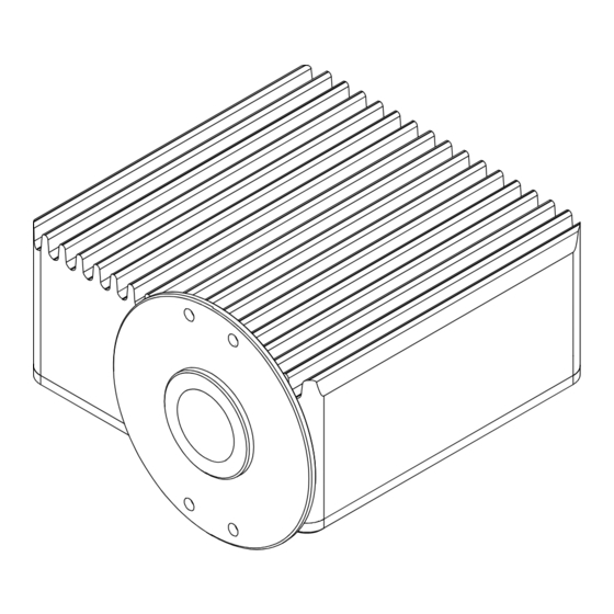
Page 10: Product Description
A computer program compares the data sequence curve with a calibration model and in that way determines the chemical composition of the sample. 3.2 Configuration 3.2.1 Front view Fig. 2: Front View Measurement window Flange Heat sink 10/34 Operation Manual X-Sential™... -
Page 11: Rear View
Power and signal connector Type plate (part) 3.3 Scope of delivery NOTE The scope of delivery depends on the configuration of the purchase order. Accessories are delivered as per the purchase order, order confirmation, and delivery note. Operation Manual X-Sential™ 11/34... -
Page 12: Type Plate
11 Current draw 12 Certificates (maximum) 13 Operating voltage 14 Product type The following product options are possible: Letter Option Gold reflector (X-One) Lamp position rev. 1.3.2 System temperature 0 - 80 °C Humidity sensor 0-100% RH 12/34 Operation Manual X-Sential™... -
Page 13: Atex Rating
900 - 1700 nm; 11100 - 5880 cm NIR range Wavelength spectrum 350 - 900 nm; 28500 - 11100 cm Visible range Number of pixels NIR Number of pixels VIS Detector Diode array Average measurement 20 spectra/s time Operation Manual X-Sential™ 13/34... - Page 14 ASDC (Advanced Spectral Drift Control): active tempera- tion ture control to ±1°C from set system operating tempera- ture. Deviations will lead to automatic white reference mea- surement to account for spectral drifts. ATEX Dust: II 3D Ex tc IIIC T85°C Da/Dc X 14/34 Operation Manual X-Sential™...
-
Page 15: Installation Box
-10 °C ≤ Tamb ≤ +40 °C Max. relative air humidity < 90 % non-condensing Storage temperature max. 45 °C 3.6.4 Materials Component Materials of construction Casing Aluminium (nickel coated), SS 316L 1.4404 flange Seals NBR (standard sealing material) FFKM (optional) Operation Manual X-Sential™ 15/34... -
Page 16: Software
At least 80 GB free disk space Use a hard disk suitable for continuous operation. Data backup At least 0.5 GB free disk space Network or external hard Additional 20 MB per day and sensor disk 16/34 Operation Manual X-Sential™... -
Page 17: Installation Site (Laboratory)
The installation site has a sample removal point at a distance of < 1 m. — The installation site allows a direct product measurement. — The installation site has constant product flow. — The layer thickness of the product to be measured is at least 30 mm. Operation Manual X-Sential™ 17/34... -
Page 18: Transport And Storage
4.2 Storage Make sure that the ambient conditions are complied with (see Chapter 3.6 "Technical data", page 13). Wherever possible, store the device in its original packaging. After storage, check the device for damage and replace if necessary. 18/34 Operation Manual X-Sential™... -
Page 19: Installation
Büchi Labortechnik AG Installation | 5 5 Installation 5.1 Establishing installation point The fixing points or bolts conform to M6 A2-70/7.3 Nm. Establish the installation point according to the specified data of the flange. Fig. 5: Dimensions of flange Operation Manual X-Sential™ 19/34... -
Page 20: Installation Point In Piping System (Example)
Büchi Labortechnik AG 5 | Installation 5.2 Installation point in piping system (example) < 1 m Fig. 6: Configuration Flow restrictor Bypass Analyser Sample removal point Flow restrictor 20/34 Operation Manual X-Sential™... -
Page 21: Installation (Example)
Remote access via Ethernet Remote computer SX-Client Display: Data cable - Results - Charts (RS422) SX-Plus Installation box Chemometric software with mains adapter manual calibration 1 sensor per measurement Up to 4 sensors per computer point Operation Manual X-Sential™ 21/34... -
Page 22: Sensor Installation
Tightening torque: 8.4 Nm +-1 Precondition: Installation point has been established. See Chapter 5.1 "Establishing installation point", page 19. The fixing points or bolts conform to M6 A2-70 15 mm Fix the sensor to the installation point using the bolts. 22/34 Operation Manual X-Sential™... -
Page 23: Connecting The Sensor
Connect the sensor cable to the sensor. Secure the connector. Tightening torque: 2.5 Nm ± 0.5 Attach the cable guard to the sensor. Tightening torque: 2 Nm ± 0.5 Attach the ground cable to the sensor. Operation Manual X-Sential™ 23/34... -
Page 24: Establishing Electrical Connections
Risk of instrument damage because of not suitable power supply cables. Not suitable power supply cables can cause bad performance or an instrument damage Use only BUCHI power supply cables. Precondition: The electrical installation is as specified on the type plate. -
Page 25: Operation
Remove the sample at the sample removal point. Mark sample with date, time and sensor number. Carry out a laboratory analysis. Insert the reference data in the journal for creating the calibration model. See SX- Suite User Manual and SX-Plus User Manual Operation Manual X-Sential™ 25/34... -
Page 26: Cleaning And Servicing
If they are dirty, clean them. Optics Annually NOTICE! Have operation carried out by NIR-Online service techni- cian Replace lamps. Casing NOTICE! Have operation carried Annually out by NIR-Online service techni- cian Check and replace seals 26/34 Operation Manual X-Sential™... - Page 27 When disposing, observe the disposal regulations of the materials used. For the used materials see Chapter 3.6 "Technical data", page 13. 8.2 Returning the instrument Before returning the instrument, contact the NIR-Online GmbH Service Department. service.nir-online@buchi.com and ask for an RMA number. Operation Manual X-Sential™ 27/34...
- Page 28 Siemens LOGO!Power Power Supply 12,7 V 11063076 9.2.2 Mounting accessories Mounting accessories are hardware interfaces between the instrument and the process. Depending on the setup, specific mounting accessories might be needed for an implementation into the production facility. 28/34 Operation Manual X-Sential™...
- Page 29 Operating pressure: -0.5 to 30bar. Max. pressure 100 bar short term — Purge port M5 (ø4mm tube adapter needed) to prevent condensation or detect leakage — The upper and lower hopper diameter has to be specified upon order Operation Manual X-Sential™ 29/34...
- Page 30 1 and 15 mm with additional adapter — DN 50 flange (other sizes upon request) — Clearance volume max. 120 mm³ Cells can be customized with different diameter and flanges There are various dimensions of the X-Cell available in the pricelist. 30/34 Operation Manual X-Sential™...
- Page 31 Product temperature above 70 °C to 130 °C. A flow rate of 5 l water per hour at 20 °C is required — 40 °C over temp switch for external alarm purpose, NO (Normally Open) circuit — Water connectors for 8/6 mm hose Operation Manual X-Sential™ 31/34...
- Page 32 Fig. 8: Pin assignment PIN 1- blue, ground PIN 2- red, 12.7 VDC PIN 3- green, RxD- PIN 4- yellow, TxD+ PIN 5- white, TxD- PIN 6- brown, RxD+ PIN 7- not connected PIN 8- not connected 32/34 Operation Manual X-Sential™...
- Page 33 PIN 1 green, TxD- (A) Pin 2 white (from green), TxD+ (B) Pin 3 orange, RxD+ (B) Pin 4 white (from orange). RxD- (A) When using the supplied Moxa D-Sub 9-pole connector, swap the cables on pin 1 and 2. Operation Manual X-Sential™ 33/34...
- Page 34 We are represented by more than 100 distribution partners worldwide. Find your local representative at: www.buchi.com...
Need help?
Do you have a question about the X-Sential and is the answer not in the manual?
Questions and answers