Advertisement
Quick Links
INSTALLATION &
OPERATION MANUAL
BCD315MW &
BCD315MY
DC-SOURCE
BATTERY CHARGER
An ISO9001:2015 Registered Company
Battery Chargers
•
Inverters
•
Power Supplies
•
Voltage Converters
101-8128 River Way, Delta B.C. V4G 1K5 Canada T. 604.946.9981 F. 604.946.9983 TF. 800.668.3884 (US/CANADA)
www.analyticsystems.com
Advertisement

Related Manuals for Analytic Systems BCD315MW


Summary of Contents for Analytic Systems BCD315MW
- Page 1 INSTALLATION & OPERATION MANUAL BCD315MW & BCD315MY DC-SOURCE BATTERY CHARGER An ISO9001:2015 Registered Company Battery Chargers • Inverters • Power Supplies • Voltage Converters 101-8128 River Way, Delta B.C. V4G 1K5 Canada T. 604.946.9981 F. 604.946.9983 TF. 800.668.3884 (US/CANADA) www.analyticsystems.com...
- Page 2 DC SOURCE BATTERY CHARGER IMPORTANT SAFETY INSTRUCTIONS SAVE THESE INSTRUCTIONS — This manual contains important safety and operating instructions for the battery charger. BATTERY CHARGER PRECAUTIONS 1. Do not expose the battery charger to rain or snow unless it is a sealed model. 2.
- Page 3 MEDICAL EQUIPMENT NOTICE Analytic Systems does not recommend the use of their products in life support applications where failure or malfunction of the product can be reasonably expected to cause failure of the life support device or to significantly affect its safety or effectiveness.
-
Page 4: Table Of Contents
• Main Parts • Operation/Operational Indicators • Charging Profiles • Connections • Installation • Battery Temperature Sensor/Equalize Cycle • Troubleshooting • Specifications • Special Services and Options • Warranty Copyright (2005-2022) Analytic Systems Ware (1993) Ltd. Revised - Aug 9, 2023... - Page 5 Introduction The BCD315MW is a C.O.T.S DC-source battery charger designed to provide up to 300 watts of precision charging power to a one or two bank battery system at 12, 24, 32, 36, or, 48 VDC. The batteries must share a common ground.
-
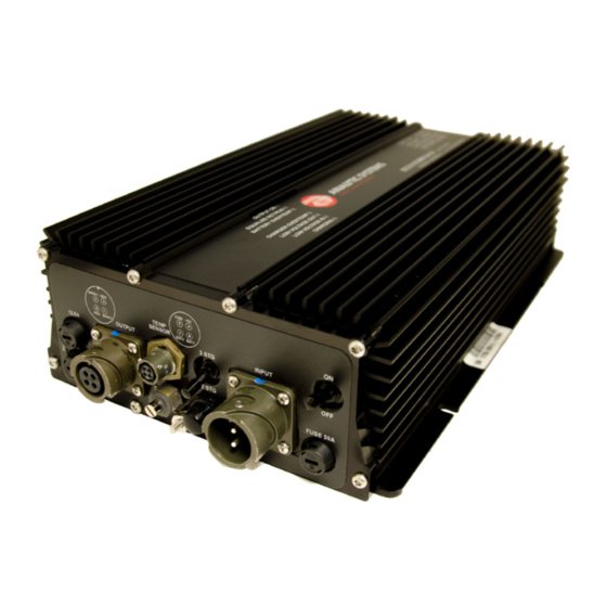
Page 6: Main Parts
Main Parts FRONT PANEL Indicator LEDs Equalize Cycle Start Button Battery Temperature Sensor Connection Charging Profile select switch Output Fuse Power Switch DC Output Connection Input Fuse Output Voltage Adjust 10. DC Input Connection... - Page 7 Operation This battery charger is designed for simple operation. Before operating, the unit must be properly installed and connected. See Installation for more information regarding mounting and connections. TO CHARGE A BATTERY Choose which type of charging profile will be used during charging by moving the Stage Select switch.
- Page 8 Operational Indicators This unit’s top panel features seven indicator LEDs on its front panel to display the unit’s operating condition. The meanings of these LEDs are detailed below. For more information regarding the malfunctions these LEDs can indicate and how to correct them, see Troubleshooting.
-
Page 9: Charging Profiles
Charging Profiles This unit has both two-stage and three-stage charging capability. You can choose which type of charging is used during operation by using the Stage Select switch located on the front panel. Below are explanations of the two charging profiles: TWO-STAGE CHARGING The battery is charged at constant current until the battery’s voltage... -
Page 10: Connections
Connections INPUT CONNECTION The DC Input connection is intended for connection to the DC power source that is powering the battery charger. This unit is equipped with an Amphenol Industrial Circular MIL-spec GTS02R16-11P connector to serve as a DC input connection. This connector’s pin-out is as follows: Function Positive Negative... -
Page 11: Installation
Installation MOUNTING Mount the unit and allow at least 1 inch of clearance around the heat sink fins for adequate cooling. CAUTION: NEVER CONNECT OR DISCONNECT ANYTHING TO THE UNIT’S INPUT OR OUTPUT WHILE IT IS ON! To prevent the risk of high voltage electric shock, never connect or disconnect anything to/from the unit’s input or output connections while the power switch is ON. - Page 12 BATTERY TEMPERATURE SENSOR CONNECTION This unit is equipped with an Amphenol MIL-Spec PT02A8-4S connector to connect to up to two Analytic Systems waterproof battery temperature sensors. This connection’s pinout can be found on the unit label. TO INSTALL THE SENSOR AT THE BATTERY: •...
- Page 13 TO PERFORM AN EQUALIZE CYCLE: Connect the supplied Analytic Systems battery temperature sensor and install it at the battery. See Battery Temperature Sensor, for more information on how to do this. .
-
Page 14: Troubleshooting
Troubleshooting This unit is fitted with several LED indicators and an alarm buzzer to display and diagnose any problems during operation. In the event of a malfunction, the unit will sound the alarm buzzer prior to shutting itself down. You should immediately check which LEDs are glowing to determine the cause of the malfunction, which are detailed in the chart below. - Page 15 Analytic Systems supports the high-quality products with the following limited product warranty: 1. The equipment manufactured by Analytic Systems Ware (1993) Ltd. (the “Warrantor”) is warranted to be free from defects in workmanship and materials under normal use and service.
- Page 16 This page has been intentionally left blank.
- Page 17 This page has been intentionally left blank.
- Page 18 This page has been intentionally left blank.
-
Page 19: Specifications
Specifications Input Nominal Voltage 12 VDC 24 VDC 36 VDC 48 VDC 72 (rail) VDC Actual Voltage 11-16 VDC 20-35 VDC 30-45 VDC 40-60 VDC 65-90 VDC Input Amps (Max) 30 A 18.7 A 12.5 A 9.4 A 5.7 A Input Fuse (MDA) 20-Amp (x2) 25-Amp 20-Amp... - Page 20 DESIGNED AND MANUFACTURED BY 800-668-3884 604-946-9983 Support@analyticsystems.com www.analyticsystems.com Battery Chargers • Inverters • Power Supplies • Voltage Converters 101-8128 River Way Delta, B.C. V4G 1K5 | Canada Register Products Online | www.analyticsystems.com/support/warranty-registration...
Need help?
Do you have a question about the BCD315MW and is the answer not in the manual?
Questions and answers