
Related Manuals for ProsKit MT-7625


Summary of Contents for ProsKit MT-7625
- Page 1 MT-7625 Optical Power Meter & Tone Probe Kits User’s Manual SC AN dB m English 繁体中文 简体中文 P UL L LOC K...
- Page 2 MT-7625 Optical Power Meter & Tone Probe Kits User’s Manual SC AN dB m English P UL L LOC K...
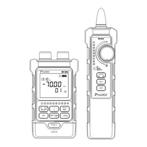
- Page 3 Host dB m P UL L LOC K Module detachable VFL Connector LED Light OPM Connector RJ45 Socket(Continue and crimping test) Keypad RJ45 Socket(Network cable tracing) Network Cable Test Module Type-C Port...
- Page 4 Receiver SC AN Probe Headset Jack Status Indicator Keypad LED Light Power Switch Type-C Port RJ45 Socket...
- Page 5 Display Description Ve r dB m 1. . . 8 LED Light Auto Power-off Battery Level Power Test Socket Position OPM Information Area Network Cable Crimping RJ45 Cable Test Cable tracing(digital) Cable tracing(analog)
- Page 6 On/Off(Host) dB m P UL L LOC K Short press " " to turn on the power with auto-off function, automatically shut down after 10 minutes of no operation. To turn off the auto-off function, long press " " to turn on the device in the off state. The " "...
- Page 7 Charge(Host) dB m P UL L LOC K Use the recommended power adapter and cable to connect to the Type-c interface. The " " icon lights up, indicating that the power supply is connected. The " " icon displays dynamically increasing, and when fully charged, the "...
- Page 8 Charge(Receiver) SC AN Use the recommended power adapter and cable to connect to the Type-c interface. The icon lights up, indicating that the power supply is connected. Green light, battery power is normal. The green light flashes, indicating low battery power. Red light, charging status.
- Page 9 Optical Power Meter dB m P UL L LOC K After power on, short press the " " to switch the measurement wavelength. The device supports measure- ment of 10 calibration wavelengths: 850nm,980nm, 1270nm, 1300nm, 1310nm, 1490nm, 1550nm, 1577nm, 1625nm, 1650nm. Short press the " "...
- Page 10 OPM Data Storage and Viewing dB m S a ve P UL L LOC K Storage: Long press " " in the optical power meter interface to store the current measurement information, and the current storage serial number will be displayed on the interface. The device can store up to 500 pieces of data.
- Page 11 OPM Offset Setting dB m O ffS e t P UL L LOC K Long press " " to enter the offset setting interface, short press " " to switch wavelength, short press " " , and " " to adjust the set offset, the setting range is [-5, +5], short press "...
- Page 12 VFL/LED Light dB m P UL L LOC K Short press " " to switch VFL output mode: CW/Glint/OFF. The " " icon will be displayed in sync status. Short press " " to turn on/off LED lighting. The " "...
- Page 13 Network Cable Test(Module) Ve r dB m 1. . . 8 P UL L LOC K P UL L LOC K Unplug the network cable test module, short press " " to enable the network cable test , the " "...
- Page 14 Network Cable Test(Receiver) Ve r dB m 1 . . . 8 SC AN P UL L LOC K Short press " " to enable the network cable test , and the " " icon will display the synchronization status. 1.
- Page 15 Network Cable test-Crimping Function Ve r dB m P UL L LOC K Short press " " twice to enable the network cable test crimping function, and the " " icon will be displayed in sync status. Connect the tested connector to the RJ45 test socket on the left side of the host.
- Page 16 Network Cable Tracing-Host Settings (Analog) Ve r dB m P UL L LOC K Short press " " three times to turn on the cable tracing function (analog), the " " icon will display the synchronization status, and the " "...
- Page 17 Network Cable Tracing-Receiver Settings (Analog) The red indicator light is on, indicating that the receiver is in analog signal receiving mode, and the green SC AN indicator light is on, indicating that the receiver is in digital signal receiving mode. Turn the receiver knob clockwise to turn the receiver on.
- Page 18 Network Cable Tracing-Host Settings (Digital) Ve r dB m P UL L LOC K Short press " " four times to turn on the cable tracing function (digital), the " " icon will display the synchronization status, and the " "...
- Page 19 Network Cable Tracing-Receiver Settings (Digital) SC AN Turn the receiver knob clockwise to turn the receiver on. Short press " SC AN " to turn on the cable tracing function (digital). At this time, the receiver will beep and the green backlight of the button will light up.
- Page 20 Receiver- NCV Function SC AN Turn the receiver knob clockwise to turn the receiver on. Short press " " to turn on the NCV mode. When a voltage greater than the threshold is detected, the receiver horn will make a "beep" sound, and the ring light on the probe will flash.
- Page 21 Receiver-LED light function SC AN Turn the receiver knob clockwise to turn the receiver on. Short press " " to turn on the LED light function.
-
Page 22: Data Communication
Communication: Use a USB-C data cable to connect the host to the PC, install the communication software on the PC to perform data transfer operations. The " " icon flashes, indicating that communication is in progress. Software download link: https://www.prokits.com.tw/Product/MT-7625/... -
Page 23: Specification
Specification Optical Power Meter Specifications and Functions Detector Type InGaAs Wavelength 700-1700nm Response Range 2.5mm universal connector OPM Connector Measurement 850/980/1270/1300/1310/1490/1550/1577/1625/ Wavelengths 1650nm Measurement Range -70~+10dBm Accuracy* (1550,1310nm)±0.2dB,(850nm,980nm,1300nm,1490 nm,1625nm,1650nm)±0.3dB,(1270nm,1577nm)±1dB Resolution 0.01dB Unit dB,dBm, mW, uW, nW Modulation 270/330/1k/2kHz(Only for Pro’sKit Light Source Detection products)... - Page 24 Specification Audio Hunt function Hunting Function Analog & Digital Mode Detection Frequency 455kHz Detection Distance 600m Line Pressing Function Crimp Detection RJ45 8pin: >10cm Illumination LEDx1 Auto Power-off Yes(no operation in 10 minutes) Low Battery Indicator Battery level Charging Socket Type-C Charging time <3hours...
- Page 25 Specification Non-contact Electricity Test Function Non-contact Voltage AC 90V-1000V Detection Indicator Light LED ×1(ring) Speaker Audio 1500HZ LED Light Functions Illumination LED×1 Headset Jack Φ3.5mm×1 Charging Socket Type-C Power Source Li-ion 3.7V 450mAh Working Current ≤250mA Size 180*45*26mm Weight 100g Packing List Type-C Charging Cable x1, Headset x1, RJ45 Patch-cord x1, Alligator Clip Patch-cord x1, Bag,...
-
Page 26: Troubleshooting
Troubleshooting Failure Failure Cause Solution Cannot power on battery power Charge the battery is too low Immediately shutdown Low battery Charge the battery after power on The operation The instrument program turn on the device is invalid is disordered again improper The face of the Clean the fiber... - Page 27 多功能光功率计/MT-7625 Optical Power Meter & Tone Probe Kits 操作手册 User’s Manual SC AN dB m English 繁体中文 P UL L LOC K...
- Page 28 主机 dB m P UL L LOC K 模块可拆卸 VFL接口 LED灯 OPM接口 RJ45测试插座(对线、压线测试) 按键区 RJ45寻线测试插座 Type-C 网线测试模块...
- Page 29 接收器 SC AN 探头 耳机孔 状态指示灯 按键区 LED环灯 开关旋钮 Type-C RJ45测试插座...
- Page 30 显示说明 Ve r dB m 1 . . . 8 VFL图标 LED图标 USB通信图标 电源图标 关闭省电模式图标 电量指示图标 光功率计信息区域 测试插座位置 网线对线功能图标 网线压线功能图标 寻线功能(模拟) 寻线功能(数字)
- Page 31 主机开关机 dB m P UL L LOC K 短按“ ”键开机,并且自动开启省电功能, 无操作10分钟自动关机。若要关闭省电功能,需在关机状 态下,长按“ ”开机。“ ”图标在顶部亮 起,表示省电功能关闭。开机后短按“ ”键开启 或关闭屏幕背光。在任意界面下长按“ ”键关 机。...
- Page 32 主机充电 dB m P UL L LOC K 使用推荐规格的电源适配器及线材接入Type-c接口, “ ”图标亮起,表示电源已连接。“ ”图标显 示动态递增,充满电时“ ”图标静止。 *推荐的电源适配器规格:5V/1A...
- Page 33 接收器充电 SC AN 使用推荐规格的电源适配器及线材接入Type-c接口,指 示灯亮起,表示电源已连接。 绿灯,电池电力正常 绿灯闪烁,电池低电量提示 红色,充电状态 *推荐的电源适配器规格:5V/1A...
- Page 34 光功率计 dB m P UL L LOC K 开机后进入光功率计界面,短按“ ”键切换测 量波长,设备支持10个校准波长的测量:850nm、980nm、 1270nm、1300nm、1310nm、1490nm、1550nm、1577nm、 1625nm、1650nm。短按“ ”键切换单位和查看REF 设定值,长按可将当前测量值设定为新的REF值。...
- Page 35 光功率存储和查看 dB m S a ve P UL L LOC K 存储:光功率计界面下长按“ ”键可存储当 前测量信息,界面上会显示当前存储序号。设备可存储多 达500条数据,超过500条之后会覆盖第一条记录。 查看:光功率计界面下长按“ ”键进入存储值 查看界面。使用“ ”、“ ”键进行翻页操 作,支持长按快速翻页。短按“ ”键退出存储界 面。...
- Page 36 光功率偏移量设置 dB m O ffS e t P UL L LOC K 长按“ ”键进入偏移量设置界面,短按 “ ”键切换波长,短按“ ”键, “ ”键调整设置偏移量,设置范围【-5,+5】, 短按“ ”键,确认偏移设置,并退出。...
- Page 37 VFL/LED手电筒 dB m P UL L LOC K 短按“ ”键切换VFL状态:开启/闪烁/关闭。 “ ”图标会同步状态显示。 短按“ ”键切换LED手电筒状态:开启/关 闭。“ ”图标会同步状态显示。...
- Page 38 网线测试-对线(模块) Ve r dB m 1 . . . 8 P UL L LOC K P UL L LOC K 拔下网线测试模块,短按“ ”键开启网线测试 对线功能,“ ”图标会同步状态显示。 1. . . 8 将网线两端分别接入主机和模块,根据主机UI和模块 指示灯点亮状态可判断网线是否合格。 “ ”闪烁提示网线插入左侧RJ45测试插座。...
- Page 39 网线测试-对线(接收器) Ve r dB m 1. . . 8 SC AN P UL L LOC K 短按“ ”键开启网线测试对线功能, “ ”图标会同步状态显示。 1 . . . 8 将网线两端分别接入主机和模块,根据主机UI和模块 指示灯点亮状态可判断网线是否合格。...
- Page 40 网线测试-压线 Ve r dB m P UL L LOC K 短按两次“ ”键开启网线测试压线功能, “ ”图标会同步状态显示。 将网线待测水晶头接入主机左侧RJ45测试插座,根据 主机UI指示灯点亮状态可判断网线是否合格。 “ ”亮起压接测试不合格,对应压接失败的线芯序 号LED灯闪烁。“ ”亮起压接测试合格。 “ ”闪烁提示网线插入左侧RJ45测试插座。...
- Page 41 网线测试-寻线功能主机设置(模拟) Ve r dB m P UL L LOC K 必须配合接收器模式使用。短按三次“ ”键 开启寻线功能(模拟),“ ”图标会同步状态显示, “ ”LED会连续闪烁。 将网线待测水晶头接入主机右侧RJ45测试插座,此时 寻线功能主机设置完成,开始设置接收器 。 “ ”闪烁提示网线插入右侧RJ45测试插座。...
- Page 42 网线测试-寻线功能接收器设置(模拟) SC AN 红色指示灯亮,表示接 收器在模拟信号接收模 式,绿色指示灯亮,表 示接收器在数字信号接 收模式。 顺时针旋转接收器旋钮,打开接收器。短按“ ”键 SC AN 开启寻线功能(模拟),此时会接收器会发出蜂鸣声,且按钮红 色背光亮起。 当探测器逐渐靠近测试网线时,接收器会发出规律的蜂 鸣提醒,并且上面的灯环会闪烁。接收器上的调节旋钮用于调 节灵敏度大小(顺时针到底灵敏度最大)。 ▲注意:在网络中寻线时,因为网络交换机原因(发射器发 射信号,通过交换机内部电路传输到其它网线端口),与目 标网线临近的几根网线可能都有音频信号,此时,可以尝试 逆时针旋转接收器灵敏度旋钮,降低接收灵敏度的方法来查 找目标网线。 注意:主机和接收器的模式需要一致,否则接收不到信号。...
- Page 43 网线测试-寻线功能主机设置(数字) Ve r dB m P UL L LOC K 必须配合接收器模式使用。短按四次“ ”键 开启寻线功能(数字),“ ”图标会同步状态显示, “ ”LED会连续闪烁。 将网线待测水晶头接入主机右侧RJ45测试插座,此时 寻线功能主机设置完成,开始设置接收器。 “ ”闪烁提示网线插入右侧RJ45测试插座。...
- Page 44 网线测试-寻线功能接收器设置(数字) SC AN 顺时针旋转接收器旋钮,打开接收器。短按“ ” SC AN 键开启寻线功能(数字),此时会接收器会发出蜂鸣声,且按钮 绿色背光亮起。 当探测器逐渐靠近测试网线时,接收器会发出规律的蜂 鸣提醒,并且上面的灯环会闪烁。接收器上的调节旋钮用于 调节灵敏度大小(顺时针到底灵敏度最大)。 ▲注意:在网络中寻线时,因为网络交换机原因(发射器发 射信号,通过交换机内部电路传输到其它网线端口),与目 标网线临近的几根网线可能都有音频信号,此时,可以尝试 逆时针旋转接收器灵敏度旋钮,降低接收灵敏度的方法来查 找目标网线。 注意:主机和接收器的模式需要一致,否则接收不到信号。...
- Page 45 接收器-NCV功能 SC AN 顺时针旋转接收器旋钮,打开接收器。短按“ ” 键开启NCV模式,当探测到大于阈值电压时,接收器喇叭发出 “滴滴声”,并且探头上环灯会闪烁。 注意:临近的外部干扰源(如无接地的充电器等),可能 会触发非接触电压的探测。 即使没有指示,电压仍然可能存在。不要仅仅依靠非接触 电压探测器来判断导线是否存在电压。探测操作可能会受到插 座设计、绝缘厚度及类型不同等因素的影响。...
- Page 46 接收器-LED照明功能 SC AN 顺时针旋转接收器旋钮,打开接收器。短按“ ” 键开启LED照明功能。...
- Page 47 数据通信 dB m R E F P UL L LOC K PC端通信:使用USB-C数据线将主机连接到PC端,在 PC端安装上位机软件以进行数据通信相关操作,“ ” 图标闪烁,表示正在通信中。 软件下载链接: https://www.prokits.com.tw/Product/MT-7625/...
- Page 48 产品规格 光功率计主机规格及功能 探测器类型 InGaAs 波长响应范围 700-1700nm 功率计接口 2.5mm 通用接口 测量波长 850/980/1270/1300/1310/1490/1550/1577/1625/1650nm 测量范围 -70~+10dBm 准确度* (1550,1310nm)±0.2dB,(850nm,980nm,1300nm,1490nm, 1625nm,1650nm)±0.3dB,(1270nm,1577nm)±1dB 分辨率 0.01dB 显示单位 dB,dBm, mW, uW, nW 频率识别 270/330/1k/2kHz(仅针对宝工光源产品) 数据存储 500 组 波长记忆 用户自校准 相对值测量 屏幕背光 红光功能 输出功率 15mW 测试距离** 10-12km @SM 红光源接口 2.5mm 通用接口 红光波长...
- Page 49 产品规格 压线功能 压接检测 RJ45 8pin: >10cm 辅助照明 LEDx1 自动关机 可选(10分钟内无操作) 电池低电量 电池电量 充电接口 Type-C 充电时间 <3hours 工作时间 >30 hours(功率计模式) 电池 聚合物锂电池3.7V/450mAh 使用温度 -10~50℃ 环境湿度 <90%RH 尺寸 114*65*29mm 重量 120g 接收器功能及规格 电源开关 旋钮操作 功能选择 硅胶按键X3 响应频率 455KHz 音量 ≥85dB 接收器信号 模拟/数字 喇叭音频...
- Page 50 产品规格 充电接口 Type-C 电池 聚合物锂电池 3.7V 450mAh 工作电流 ≤250mA 尺寸 180*45*26mm 重量 100g 配件 Type-C充电线x1、耳机x1、RJ45跳线x1 、RJ45鳄 鱼夹跳线x1、牛津布包、说明书 *测试条件: 23℃±2℃, 40%-60%RH,使用标准测试线。 准确度范围:+3dBm~-60dBm,其余参考如下: ±0.8dB: +3dBm~+6dBm, -60dBm~-65dBm@1550nm ±3.0dB: +6dBm-+10dBm,-65dBm--70dBm@1550nm ** 测试距离受环境条件及视觉敏感度影响。 一般维护 光纤连接适配器应避免与硬物接触,并保持清洁。存放时应通 风干燥,避免受潮。长期不使用时,每隔3个月充一次电,充入 50%-80%的电量。 用户可处理的故障 故障名 故障原因 处理办法 不能开机 电池没电 给电池充电 开机后马上关机 电池电量低...
- Page 51 多功能光功率计/MT-7625 Optical Power Meter & Tone Probe Kits 操作手册 User’s Manual SC AN dB m 简体中文 P UL L LOC K...
- Page 52 主机 dB m P UL L LOC K 模块可拆卸 VFL接口 LED灯 OPM接口 RJ45测试插座(对线、压线测试) 按键区 RJ45寻线测试插座 Type-C 网线测试模块...
- Page 53 接收器 SC AN 探头 耳机孔 状态指示灯 按键区 LED环灯 开关旋钮 Type-C RJ45测试插座...
- Page 54 显示说明 Ve r dB m 1 . . . 8 VFL图标 LED图标 USB通信图标 电源图标 关闭省电模式图标 电量指示图标 光功率计信息区域 测试插座位置 网线对线功能图标 网线压线功能图标 寻线功能(模拟) 寻线功能(数字)
- Page 55 主机开关机 dB m P UL L LOC K 短按“ ”键开机,并且自动开启省电功能,无 操作10分钟自动关机。若要关闭省电功能,需在关机状态 下,长按“ ”开机。“ ”图标在顶部亮起, 表示省电功能关闭。开机后短按“ ”键开启或关闭 屏幕背光。在任意界面下长按“ ”键关机。...
- Page 56 主机充电 dB m P UL L LOC K 使 用 推 荐 规 格 的 电 源 适 配 器 及 线 材 接 入 T y p e - c 接 口,” ”图标亮起,表示电源已连接。“ ”图标 显示动态递增,充满电时“ ”图标静止。 *推荐的电源适配器规格:5V/1A...
- Page 57 接收器充电 SC AN 使用推荐规格的电源适配器及线材接入Type-c接口,指 示灯亮起,表示电源已连接。 绿灯,电池电力正常 绿灯闪烁,电池低电量提示 红色,充电状态 *推荐的电源适配器规格:5V/1A...
- Page 58 光功率计 dB m P UL L LOC K 开机后进入光功率计界面,短按“ ”键切换测 量 波 长 , 设 备 支 持 1 0 个 校 准 波 长 的 测 量 : 8 5 0 n m 、 980nm、1270nm、1300nm、1310nm、1490nm、 1 5 5 0 n m 、 1 5 7 7 n m 、 1 6 2 5 n m 、 1 6 5 0 n m 。 短 按 “...
- Page 59 光功率存储和查看 dB m S a ve P UL L LOC K 存储:光功率计界面下长按“ ”键可存储当前 测量信息,界面上会显示当前存储序号。设备可存储多达 500条数据,超过500条之后会覆盖第一条记录。 查看:光功率计界面下长按“ ”键进入存储值 查看界面。使用“ ”、“ ”键进行翻页操 作,支持长按快速翻页。短按“ ”键退出存储界面。...
- Page 60 光功率偏移量设置 dB m O ffS e t P UL L LOC K 长按“ ”键进入偏移量设置界面,短按 “ ”键切换波长,短按“ ”键,“ ” 键调整设置偏移量,设置范围【-5,+5】,短按 “ ”键,确认偏移设置,并退出。...
- Page 61 VFL/LED手电筒 dB m P UL L LOC K 短按“ ”键切换VFL状态:开启/闪烁/关闭。 “ ”图标会同步状态显示。 短按“ ”键切换LED手电筒状态:开启/关 闭。“ ”图标会同步状态显示。...
- Page 62 网线测试-对线(模块) Ve r dB m 1 . . . 8 P UL L LOC K P UL L LOC K 拔下网线测试模块,短按“ ”键开启网线测试对 线功能,“ ”图标会同步状态显示。 1 . . . 8 将网线两端分别接入主机和模块,根据主机UI和模块指 示灯点亮状态可判断网线是否合格。 “ ”闪烁提示网线插入左侧RJ45测试插座。...
- Page 63 网线测试-对线(接收器) Ve r dB m 1. . . 8 SC AN P UL L LOC K 短按“ ”键开启网线测试对线功能,“ ” 1. . . 8 图标会同步状态显示。 将网线两端分别接入主机和模块,根据主机UI和模块指 示灯点亮状态可判断网线是否合格。...
- Page 64 网线测试-压线 Ve r dB m P UL L LOC K 短按两次“ ”键开启网线测试压线功能, “ ”图标会同步状态显示。 将网线待测水晶头接入主机左侧RJ45测试插座,根据主 机UI指示灯点亮状态可判断网线是否合格。“ ”亮 起压接测试不合格,对应压接失败的线芯序号LED灯闪烁。 “ ”亮起压接测试合格。 “ ”闪烁提示网线插入左侧RJ45测试插座。...
- Page 65 网线测试-寻线功能主机设置(模拟) Ve r dB m P UL L LOC K 必须配合接收器模式使用。短按三次“ ”键开 启寻线功能(模拟),“ ”图标会同步状态显示, “ ”LED会连续闪烁。 将网线待测水晶头接入主机右侧RJ45测试插座,此时寻 线功能主机设置完成,开始设置接收器 。 “ ”闪烁提示网线插入右侧RJ45测试插座。...
- Page 66 网线测试-寻线功能接收器设置(模拟) 红色指示灯亮,表示接收 SC AN 器在模拟信号接收模式, 绿色指示灯亮,表示接收 器在数字信号接收模式。 顺时针旋转接收器旋钮,打开接收器。短按“ ” SC AN 键开启寻线功能(模拟),此时会接收器会发出蜂鸣声,且按 钮红色背光亮起。 当探测器逐渐靠近测试网线时,接收器会发出规律的 蜂鸣提醒,并且上面的灯环会闪烁。接收器上的调节旋钮 用于调节灵敏度大小(顺时针到底灵敏度最大)。 ▲注意:在网络中寻线时,因为网络交换机原因(发射 器发射信号,通过交换机内部电路传输到其它网线端口 ),与目标网线临近的几根网线可能都有音频信号,此 时,可以尝试逆时针旋转接收器灵敏度旋钮,降低接收 灵敏度的方法来查找目标网线。 注意:主机和接收器的模式需要一致,否则接收不到信号。...
- Page 67 网线测试-寻线功能主机设置(数字) Ve r dB m P UL L LOC K 必须配合接收器模式使用。短按四次“ ”键开 启寻线功能(数字),“ ”图标会同步状态显示, “ ”LED会连续闪烁。 将网线待测水晶头接入主机右侧RJ45测试插座,此时寻 线功能主机设置完成,开始设置接收器。 “ ”闪烁提示网线插入右侧RJ45测试插座。...
- Page 68 网线测试-寻线功能接收器设置(数字) SC AN 顺时针旋转接收器旋钮,打开接收器。短按“ ” SC AN 键开启寻线功能(数字),此时会接收器会发出蜂鸣声,且按 钮绿色背光亮起。 当探测器逐渐靠近测试网线时,接收器会发出规律 的蜂鸣提醒,并且上面的灯环会闪烁。接收器上的调节旋 钮用于调节灵敏度大小(顺时针到底灵敏度最大)。 ▲注意:在网络中寻线时,因为网络交换机原因(发射 器发射信号,通过交换机内部电路传输到其它网线端口 ),与目标网线临近的几根网线可能都有音频信号,此 时,可以尝试逆时针旋转接收器灵敏度旋钮,降低接收 灵敏度的方法来查找目标网线。 注意:主机和接收器的模式需要一致,否则接收不到信号。...
- Page 69 接收器-NCV功能 SC AN 顺时针旋转接收器旋钮,打开接收器。短按“ ” 键开启NCV模式,当探测到大于阈值电压时,接收器喇叭 发出“滴滴声”,并且探头上环灯会闪烁。 注意:临近的外部干扰源(如无接地的充电器等),可 能会触发非接触电压的探测。 即使没有指示,电压仍然可能存在。不要仅仅依靠非接 触电压探测器来判断导线是否存在电压。探测操作可能会 受到插座设计、绝缘厚度及类型不同等因素的影响。...
- Page 70 接收器-LED照明功能 SC AN 顺时针旋转接收器旋钮,打开接收器。短按“ ” 键开启LED照明功能。...
- Page 71 数据通信 dB m R E F P UL L LOC K PC端通信:使用USB-C数据线将主机连接到PC端,在 PC端安装上位机软件以进行数据通信相关操作,“ ” 图标闪烁,表示正在通信中。 软件下载链接: https://www.prokits.com.tw/Product/MT-7625/...
- Page 72 产品规格 光功率计主机规格及功能 探测器类型 InGaAs 波长响应范围 700-1700nm 功率计接口 2.5mm 通用接口 测量波长 850/980/1270/1300/1310/1490/1550/1577/1625/1650nm 测量范围 -70~+10dBm 准确度* (1550,1310nm)±0.2dB,(850nm,980nm,1300nm,1490nm, 1625nm,1650nm)±0.3dB,(1270nm,1577nm)±1dB 分辨率 0.01dB 显示单位 dB,dBm, mW, uW, nW 频率识别 270/330/1k/2kHz(仅针对宝工光源产品) 数据存储 500 组 波长记忆 用户自校准 相对值测量 屏幕背光 红光功能 输出功率 15mW 测试距离** 10-12km @SM 红光源接口 2.5mm 通用接口 红光波长...
- Page 73 产品规格 压线功能 压接检测 RJ45 8pin: >10cm 辅助照明 LEDx1 自动关机 可选(10分钟内无操作) 电池低电量 电池电量 充电接口 Type-C 充电时间 <3hours 工作时间 >30 hours(功率计模式) 电池 聚合物锂电池3.7V/450mAh 使用温度 -10~50℃ 环境湿度 <90%RH 尺寸 114*65*29mm 重量 120g 接收器功能及规格 电源开关 旋钮操作 功能选择 硅胶按键X3 响应频率 455KHz 音量 ≥85dB 接收器信号 模拟/数字 喇叭音频...
- Page 74 产品规格 充电接口 Type-C 电池 聚合物锂电池 3.7V 450mAh 工作电流 ≤250mA 尺寸 180*45*26mm 重量 100g 配件 Type-C充电线x1、耳机x1、RJ45跳线x1 、RJ45鳄鱼 夹跳线x1、牛津布包、说明书 *测试条件: 23℃±2℃, 40%-60%RH,使用标准测试线。 准确度范围:+3dBm~-60dBm,其余参考如下: ±0.8dB: +3dBm~+6dBm, -60dBm~-65dBm@1550nm ±3.0dB: +6dBm-+10dBm,-65dBm--70dBm@1550nm ** 测试距离受环境条件及视觉敏感度影响。 一般维护 光纤连接适配器应避免与硬物接触,并保持清洁。存放时应通 风干燥,避免受潮。长期不使用时,每隔3个月充一次电,充入 50%-80%的电量。 用户可处理的故障 故障名 故障原因 处理办法 不能开机 电池没电 给电池充电 开机后马上关机 电池电量低...
- Page 75 产品保固卡 店章 购买 日期 公司 名称 联络 电话 电子 邮箱 联络 地址 产品 型号 □ MT-7625 ※在正常使用情况下,自原购买日起12个月免费维修保证(不含耗 材,消耗品)。 ※产品保固卡需盖上店章.日期章,其保固效力始生效。 ※本卡请妥善保存,如需维修服务时,请出示本卡以为证明。 ※保固期满后,属调整,保养或是维修性质之服务,则酌收检修工时费 用。若有零件需更换,则零件费另计。 产品保固说明 ●保固期限内,如有下列情况者,维修中心则会酌收材料成本或修理 费(由本公司维修人员判定)。 •对产品表面的损伤,包括外壳裂缝或刮痕。 •因误用,疏忽,不当安装或测试,未经授权打开产品修理,修改产 品或者任何其它超出预期使用范围的原因所造成的损害。 •因事故,火灾,电力变化,其它危害,或自然灾难所造成的损害。 ●非服务保证内容: •机件本体之外之附配件:如布包,USB连接线,鳄鱼夹,跳线等附配 件。 ●超过保证期限之检修或服务,虽未更换零件,将依公司保固维修政 策酌收服务费。 制造商: 宝工实业股份有限公司 销售/生产商: 上海宝工工具有限公司 上海市浦东新区康桥东路1365弄25号 电话:021-68183050 服务热线:400 1699 629...
- Page 76 寶工實業股份有限公司 PROKIT’S INDUSTRIES CO., LTD https://www.prokits.com.tw Email: pk@mail.prokits.com.tw ©2023 Prokit’s Industries Co., LTD. All rights reserved 2023001(C)
Need help?
Do you have a question about the MT-7625 and is the answer not in the manual?
Questions and answers