Advertisement
Quick Links
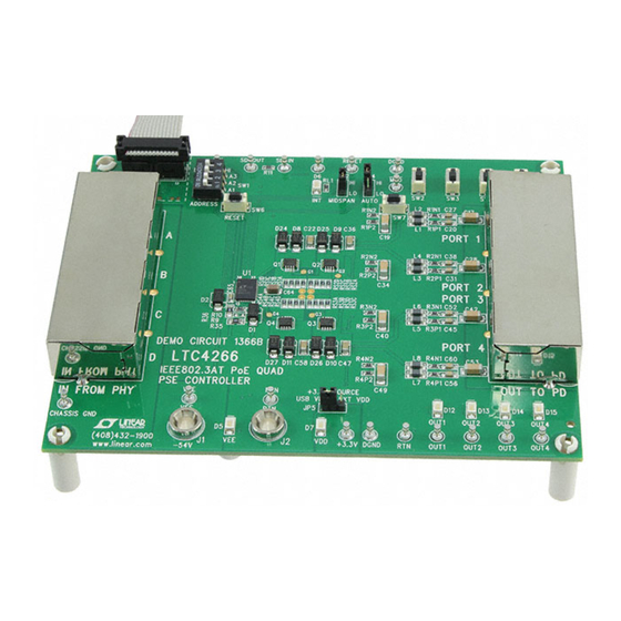
Description
Demonstration circuit DC1366B features the
quad network power controller with I
for use in IEEE 802.3at compliant Power Sourcing Equip-
ment (PSE). Integrated into a tiny 5mm × 7mm 38-pin
QFN package are four independent channels controlling
external N-channel power MOSFETs. Each port features:
Reliable 4-Point PD Detection
n
Selectable 1 or 2-Event Classification
n
Inrush Current Limiting
n
Extremely Fast Short-Circuit Protection with Program-
n
mable Foldback Current Threshold
Programmable Cutoff Current Threshold for Class
n
Power Enforcement
Voltage and Current Readback
n
DC Disconnect Sensing
n
LTC
4266, a
®
2
C
interface, designed
®
DC1366B
DEMO MANUAL DC1366B
IEEE 802.3at PoE
Quad PSE Controller
The DC1366B is configured like a midspan PSE with two
RJ45 connectors for each port such that gigabit Ethernet
data can pass through the board at full line rates while
DC power is injected by the LTC4266 on the OUT TO PD
side of the board.
Often one of the most challenging aspects of designing a
PSE system is the power management software; Linear
Technology makes the job easier with the fully-featured
LTC4266 register set and a QuikEval™ GUI software ap-
plication. The GUI allows the user full and easy access to
the LTC4266 register set with detailed contextual help info.
LTC4266 example software is available only under a non-
disclosure agreement (NDA).
The DC1366B has increased surge protection and more
compact Hot Swap™ MOSFETs over the DC1366A.
Design files for this circuit board are available at
http://www.linear.com/demo/DC1366B
L, LT, LTC, LTM, Linear Technology and the Linear logo are registered trademarks and Hot
Swap and QuikEval are trademarks of Linear Technology Corporation. All other trademarks are
the property of their respective owners.
LTC4266
dc1366bf
1
Advertisement

Related Manuals for Linear Technology DC1366B


Summary of Contents for Linear Technology DC1366B
- Page 1 Design files for this circuit board are available at DC Disconnect Sensing http://www.linear.com/demo/DC1366B L, LT, LTC, LTM, Linear Technology and the Linear logo are registered trademarks and Hot Swap and QuikEval are trademarks of Linear Technology Corporation. All other trademarks are the property of their respective owners.
-
Page 2: Quick Start Procedure
Alternatively, the user can omit the DC590 and connect an positive goes to RTN and negative to V C master device to the DC1366B. If the DC590 is omitted 8. Turn on the main power supply and verify the V then a bench power supply must provide V on the DC1366B is lit. - Page 3 Optional Equipment for Computer Control DC590 USB CABLE Windows USB to I Computer Interface 14-Pin Ribbon Cable CAT5 Cables RJ45 RJ45 RJ45 RJ45 RJ45 RJ45 RJ45 RJ45 – Isolated Optional – Supply Supply (51V to 57V) (3.3V Nominal) Figure 1. DC1366B Setup dc1366bf...
-
Page 4: Operation
R10. The DGND pin is at –3.3V below the AGND High power is disabled and is enabled by a host con- pin. The DC1366B can also be configured for a +3.3V at troller. relative to AGND by removing R10 and installing a 0Ω... - Page 5 This Each port has an individual shut down switch (SW2 signal can be accessed on the DC1366B at the INT test through SW5 for ports 1 through 4 respectively). point. An LED is also included to indicate an interrupt.
- Page 6 +3.3V above AGND and DGND is tied to AGND, the Ethernet ports can be subject to significant cable surge DC1366B has place holders at D28 and C66 for a 64V TVS events. To keep PoE voltages below a safe level and protect...
-
Page 7: Pcb Layout
DEMO MANUAL DC1366B pcB Layout Top Assembly dc1366bf... - Page 8 DEMO MANUAL DC1366B pcB Layout Layer 1 dc1366bf...
- Page 9 DEMO MANUAL DC1366B pcB Layout Layer 2 dc1366bf...
- Page 10 DEMO MANUAL DC1366B pcB Layout Layer 3 dc1366bf...
- Page 11 DEMO MANUAL DC1366B pcB Layout Layer 4 dc1366bf...
- Page 12 DEMO MANUAL DC1366B pcB Layout Bottom Assembly dc1366bf...
-
Page 13: Schematic Diagram
DEMO MANUAL DC1366B schematic Diagram dc1366bf... - Page 14 DEMO MANUAL DC1366B schematic Diagram dc1366bf...
- Page 15 Information furnished by Linear Technology Corporation is believed to be accurate and reliable. However, no responsibility is assumed for its use. Linear Technology Corporation makes no representa- tion that the interconnection of its circuits as described herein will not infringe on existing patent rights.
- Page 16 Linear Technology Corporation (LTC) provides the enclosed product(s) under the following AS IS conditions: This demonstration board (DEMO BOARD) kit being sold or provided by Linear Technology is intended for use for ENGINEERING DEVELOPMENT OR EVALUATION PURPOSES ONLY and is not provided by LTC for commercial use. As such, the DEMO BOARD herein may not be complete in terms of required design-, marketing-, and/or manufacturing-related protective considerations, including but not limited to product safety measures typically found in finished commercial goods.
Need help?
Do you have a question about the DC1366B and is the answer not in the manual?
Questions and answers