Advertisement
Description
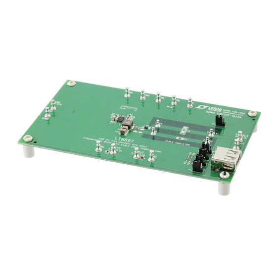
Demonstration circuit 1973A is a USB 5V 2.5A output, 42V
input synchronous buck with cable drop compensation
featuring the
LT
®
efficiency, high speed synchronous monolithic step-down
switching regulator designed to power 5V USB applica-
tions. Top and bottom power switches, compensation
components and other necessary circuits are inside of
the LT8697 to minimize external components and simplify
design. A precise output voltage and programmable cable
drop compensation maintain accurate 5V regulation at the
USB socket at the end of a long cable.
The circuit runs at 2MHz to minimize external components
size and to avoid AM band. The demo board has an EMI
filter installed. The conducted EMI performance of the
board is shown on Figure 2. The figure shows the circuit
passes the EN55022 Class B with a wide margin.
When the load current is being drawn from VCABLE, the
load current is limited by the current limit of the LT8697
or by 5.8V limit at VOUT, whichever comes first. The
rated load current of the demonstration circuit is set at
2.1A, enough for all USB applications. If higher voltage or
higher current is needed at VCABLE, refer to application
examples on the data sheet. If VCABLE is not connected
to any load, VOUT can be used to power up a load. VSYS
can also be used to supply a small load.
Arrow.com.
Downloaded from
USB 5V 2.5A Output, 42V Input Synchronous
Buck with Cable Drop Compensation
8697. The LT8697 is a compact, high
DEMO MANUAL DC1973A
When probing the board, pay attention to GND and C_GND.
On the demonstration board, they are connected together by
default through R13 so a user can connect the ground clip
of a probe to C_GND. However, if a user wants to evaluate
an actual cable, the cable will replace R4 and R13. The
copper between pads of R13 should be cut open. In this
case, C_GND is no longer the same as GND. A differential
measurement is needed to probe across the point of load.
The demonstration board also includes a USB socket.
With the proper configuration of jumpers X1, X2, X3 and
X4, the USB can be configured for different applications.
See Table 1 for configurations.
A 500mA onboard step load can also be activated to evalu-
ate the load transient response of the circuit. To active the
step load, simply set jumper X5 to V+.
The LT8697 data sheet gives a complete description of
the part, operation and application information. The data
sheet must be read in conjunction with this quick start
guide for demo circuit 1973A.
Design files for this circuit board are available at
http://www.linear.com/demo/DC1973A
L, LT, LTC, LTM, Linear Technology and the Linear logo are registered trademarks of Linear
Technology Corporation. All other trademarks are the property of their respective owners.
LT8697
dc1973af
1
Advertisement
Table of Contents

Related Manuals for Linear Technology DC1973A


Summary of Contents for Linear Technology DC1973A
- Page 1 VCABLE, refer to application examples on the data sheet. If VCABLE is not connected L, LT, LTC, LTM, Linear Technology and the Linear logo are registered trademarks of Linear Technology Corporation. All other trademarks are the property of their respective owners.
- Page 2 DEMO MANUAL DC1973A Description Figure 1. LT8697 Demo Circuit EMI Performance, Switching Frequency = 2MHz Table 1. Configure X1 – X4 for Different USB Applications Do Not Care Do Not Care Do Not Care OPEN Not in USE OPEN OPEN...
-
Page 3: Performance Summary
DEMO MANUAL DC1973A performance summary Specifications are at T = 25°C SYMBOL PARAMETER CONDITIONS UNITS Input Supply Range Output Voltage Max I Maximum Output Current Switching Frequency 2.05 Efficiency at DC = 2.1A, Measured at V Quick start proceDure Demonstration circuit 1973A is easy to set up to evalu- 5. - Page 4 DEMO MANUAL DC1973A Quick start proceDure Figure 2. Proper Measurement Equipment Setup Figure 2. Measure Output Ripple dc1973af Arrow.com. Arrow.com. Arrow.com. Arrow.com. Downloaded from Downloaded from Downloaded from Downloaded from...
-
Page 5: Parts List
DEMO MANUAL DC1973A parts List ITEM REFERENCE PART DESCRIPTION MANUFACTURER/PART NUMBER Required Circuit Components Cap., X7R 4.7µF 50V 10% 1206 TAIYO YUDEN, UMK316BJ475KL-T Cap., X5R 0.22µF 16V 10% 0603 TAIYO YUDEN, EMK107BJ224KA-T C4, C25 Cap., X7R 47µF 10V 10% 1210 MURATA, GRM32ER71A476KE15L Cap., X5R 0.1µF 16V 10% 0402... - Page 6 DEMO MANUAL DC1973A parts List ITEM REFERENCE PART DESCRIPTION MANUFACTURER/PART NUMBER Res., Chip, 0Ω, 0.25W, 1206 VISHAY, CRCW12060000Z0EA Res., Chip, 1206 Res., Chip, 75k, 0.1W, 1% 0603 VISHAY, CRCW060375K0FKEA Res., Chip, 43.2k, 0.1W, 1% 0603 VISHAY, CRCW060343K2FKEA R17, R18 Res., Chip, 49.9k, 0.1W, 1% 0603 VISHAY, CRCW060349K9FKEA Res., Chip, 10k, 0.1W, 5% 0603...
-
Page 7: Schematic Diagram
Information furnished by Linear Technology Corporation is believed to be accurate and reliable. However, no responsibility is assumed for its use. Linear Technology Corporation makes no representa- tion that the interconnection of its circuits as described herein will not infringe on existing patent rights. - Page 8 Linear Technology Corporation (LTC) provides the enclosed product(s) under the following AS IS conditions: This demonstration board (DEMO BOARD) kit being sold or provided by Linear Technology is intended for use for ENGINEERING DEVELOPMENT OR EVALUATION PURPOSES ONLY and is not provided by LTC for commercial use. As such, the DEMO BOARD herein may not be complete in terms of required design-, marketing-, and/or manufacturing-related protective considerations, including but not limited to product safety measures typically found in finished commercial goods.
Need help?
Do you have a question about the DC1973A and is the answer not in the manual?
Questions and answers