
Related Manuals for HESCH HE 5750


Summary of Contents for HESCH HE 5750
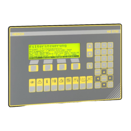
- Page 1 HE 5750 Solenoid Valve Control Operating instructions (Original Language German) # 371521| Version 2.15...
- Page 2 HESCH Industrie Elektronik GmbH, Documentation Department Copyrights © Copyright 2020 HESCH Industrie-Elektronik GmbH. All rights reserved. The content of this operating manual incl. images and design are subject to the protect of copyright and other laws regarding the protection of intel- lectual property.
-
Page 3: Table Of Contents
6.1. Network supply .......................... 18 6.2. Device Dimensions ........................18 Commissioning ........................19 7.1. In- and Outputs (rear display HE 5750) ..................19 7.2. Standard Assignment ........................ 19 7.3. Galvanic Isolation ........................19 7.4. Setting of the common baud rate in the CAN network .............. 20 7.5. - Page 4 Master – Slave CAN Communication ................74 12.1. Data Direction PLC → HE 5750 ..................76 12.2. Data direction HE 5750 → PLC ................... 77 12.3. 12.4. Diagnosis HE 5750 at PLC ....................79 Solenoid Valve Control ......................81 13.1.
- Page 5 2019-05-21 Subchapter 9.4 Table of parameters (1/3): New parameters added. Chapter 12.2 Data Direction PLC → HE 5750, 12.3. HE 5750 → PLC : Function “Parallel valve control inhibit” add- Notes added in subchapter 1.System parameters and 5. Parallel valves.
-
Page 6: Legal Regulations
Warning! The device may not be operated if damages that let assume that a safe operation is not possible. HESCH Industrie-Elektronik GmbH HE 5750, Version 2.15, 22.01.2020 # 371521... -
Page 7: Safety Guidelines
Indicates a possible endangerment with medium risk that may result in death or se- vere body injury, if not prevented. ATTENTION Indicates a possible endangerment with medium risk that may result in death or se- vere body injury, if not prevented. HESCH Industrie-Elektronik GmbH HE 5750, Version 2.15, 22.01.2020 # 371521... -
Page 8: Safety During The Individual Operating Phases
It is recommended to use twisted and shielded measuring leads to avoid the influence of interference fields. The electrical connection takes place according to the connection schedules / connection images of the re- spective device. HESCH Industrie-Elektronik GmbH HE 5750, Version 2.15, 22.01.2020 # 371521... - Page 9 The device must be protected against unin- tended operation. Prior to disconnecting, the impact and respective precautions must be considered if the device is connected to other devices and / or equipments. HESCH Industrie-Elektronik GmbH HE 5750, Version 2.15, 22.01.2020 # 371521...
- Page 10 EX conformity exists. In addition, the information of the related con- formity declaration and the respective country specifications for the installation of elec- trical systems in potentially explosive areas must be considered for these EX devices. HESCH Industrie-Elektronik GmbH HE 5750, Version 2.15, 22.01.2020 # 371521...
-
Page 11: Glossary
The differential pressure is reviewed regarding a minimum value at the same time. If the reading falls short it is as- sumed that no fan operation exists and the cleaning is discontinued. HESCH Industrie-Elektronik GmbH HE 5750, Version 2.15, 22.01.2020 # 371521... - Page 12 In connection with the operating mode partial cycle the valves can be individually processed. Drain valves The control supports the drain valves at the local manifold. Parameters 4.14 to 4.16. HESCH Industrie-Elektronik GmbH HE 5750, Version 2.15, 22.01.2020 # 371521...
-
Page 13: Device Description
2. Display and operating elements 5.2. General Description The system control HE 5750 is the central unit in a CAN based network of the clean- ing control system for industrial hose filters. The central control communicates with the decentralised valve control units HE 5724 and the damper control units HE 5740 via the industrial CAN bus. -
Page 14: Communication Structure
Device Description 5.3. Communication Structure The central control HE 5750 is the master in the CAN bus system of the filter control- ler system. A PROFIBUS or a ModBus interface is alternatively available for the con- trol technology. Altlernatively also a parallel interface for the binary signal exchange is available. -
Page 15: System Layout
Device Description With the option remote maintenance in ‘SmartTool’, a modem connection to the con- trol can be established to perform remote maintenance and diagnosis of plants. 5.5. System Layout HESCH Industrie-Elektronik GmbH HE 5750, Version 2.15, 22.01.2020 # 371521... -
Page 16: Components
Width = 380 mm Height = 300 mm Depth = 155 mm Weight: 7,5 kg 5.6.4. HE 1149 Pressure transmitter, Manifold pressure sensor Width = 78 mm Height = 48 mm HESCH Industrie-Elektronik GmbH HE 5750, Version 2.15, 22.01.2020 # 371521... - Page 17 Width = 130 mm Height = 130 mm Depth = 60 mm HE 5422 MR (with measuring hose cleaning) Width = 200 mm Height = 150 mm Depth = 100 mm HESCH Industrie-Elektronik GmbH HE 5750, Version 2.15, 22.01.2020 # 371521...
-
Page 18: Installation And Housing
The device includes a network filter. In transient interference voltages an addi- tional external network filter may be required. This is not included in the standard scope of delivery, however can be purchased via HESCH Industrie-Elektronik GmbH. 6.1. Network supply The controller requires 24 VDC. -
Page 19: Commissioning
Commissioning Commissioning 7.1. In- and Outputs (rear display HE 5750) 7.2. Standard Assignment DO1: Operation IN1: Local control DO2: Cleaning active IN2: Acknowledgement DO3: IN3: Error Local cleaning DO4: Pulse signal (1 sec) IN4: Filter stop DO5: Lamp test IN5:... -
Page 20: Setting Of The Common Baud Rate In The Can Network
In general, the following rule applies: only as fast as necessary, not as fast as possible. The factory setting is 50 kbd. Master Setting: Slave Setting: Network extension: Baud rate [kbaud] Network extension [m] 1200 HESCH Industrie-Elektronik GmbH HE 5750, Version 2.15, 22.01.2020 # 371521... -
Page 21: Setting Of The Node No. (Address)
By keeping a purely serial topology, the network extension can possibly be increased. The used cable should be permissible for CAN bus operation. Note the diameter for more extension (>= AWG18, 0.75mm HESCH Industrie-Elektronik GmbH HE 5750, Version 2.15, 22.01.2020 # 371521... -
Page 22: Local Control At Control Cabinet
SmartTool. After expiry of the time ‘Re- mote timeout’ they keyboard operation is released again, too, in case of an inter- ruption of the connection to the controller technology. HESCH Industrie-Elektronik GmbH HE 5750, Version 2.15, 22.01.2020 # 371521... -
Page 23: Network Topology Diagramm
Commissioning 7.8. Network Topology diagramm 7.8.1. 1 Slave per chamber HESCH Industrie-Elektronik GmbH HE 5750, Version 2.15, 22.01.2020 # 371521... - Page 24 Commissioning 7.8.2. 2 Slaves per chamber HESCH Industrie-Elektronik GmbH HE 5750, Version 2.15, 22.01.2020 # 371521...
-
Page 25: System Start
1. Waiting for slave messages 2. Preparation 3. Sending parameter 4. Review Actual system status - Cleaning state - Actual chamber/valve - Delta-p symbol - Delta-p value - System pressure HESCH Industrie-Elektronik GmbH HE 5750, Version 2.15, 22.01.2020 # 371521... -
Page 26: Display And Operating Keys
Display and operating keys Display and operating keys Fig. 2 HE 5750, Display and operating keys 1. F1 – F4 Context keys 2. F5 – F16 Permanent function 3. numeric keypad 4. input block 8.1. Numeric keypad and input block Additional functions, setting possibility or branchings are offered on the individual screens. -
Page 27: Function Keys F5 - F16
The warning triangle can be displayed in 2 different sizes . There are currently ac- tive alarms available Small There are currently alarms in hold position which are no longer ap- plied. HESCH Industrie-Elektronik GmbH HE 5750, Version 2.15, 22.01.2020 # 371521... - Page 28 8.2.5. Lamp Test F9 Function Display Indicator lights at the front Actuell display is not changed. door of the control cabinet are triggered. HESCH Industrie-Elektronik GmbH HE 5750, Version 2.15, 22.01.2020 # 371521...
- Page 29 8.2.8. Graphic (Delta-p/ dust development/circulation time) F12 Function Display Delta-p-, dust developing and time of circulation graphics via different time windows. Switchable be- tween both grafics by the F12 key. HESCH Industrie-Elektronik GmbH HE 5750, Version 2.15, 22.01.2020 # 371521...
- Page 30 Keys ▼ ▲ The dust sensor status is called with F3. This sta- tus indicates in % the dust content in the clean gas channel. Tabular representation also with the F2 key. HESCH Industrie-Elektronik GmbH HE 5750, Version 2.15, 22.01.2020 # 371521...
- Page 31 8.2.11. Chamber Isolation F15 Function Display Chambers are deleted from the cleaning process. The valves are not activated anymore. If existing, dam- pers are Off. HESCH Industrie-Elektronik GmbH HE 5750, Version 2.15, 22.01.2020 # 371521...
-
Page 32: Context-Sensitive Keys F1 - F4
The respective function is activated by pressing the corresponding keys F1 to F4. Navigation line Context-sensitive screens 1 During start up Hold Continues start-up for Displays the info info screen without screen for one more pause. minute. HESCH Industrie-Elektronik GmbH HE 5750, Version 2.15, 22.01.2020 # 371521... - Page 33 F8 / F16 key not loaded. Alarm Screen F6 Actual alarms and alarm protocol are displayed. Switching of display by F6 key. Acknowl. Back Acknowledge alarm Back HESCH Industrie-Elektronik GmbH HE 5750, Version 2.15, 22.01.2020 # 371521...
- Page 34 Arrow keys change the value. Can be set via the numeric keypad alternatively. ENTER-key acknowledges new value. ESC-key cancels input. F4-key cancels the input and switches to the previous level. HESCH Industrie-Elektronik GmbH HE 5750, Version 2.15, 22.01.2020 # 371521...
-
Page 35: Filter Time Of Circulation
The time of circulation is formatted as a fixed-point number in minutes with one deci- mal place Example: Time of circulation 37 => 3.7 minutes = 3 minutes and 7 * 6 seconds = 3:42 minutes. HESCH Industrie-Elektronik GmbH HE 5750, Version 2.15, 22.01.2020 # 371521... -
Page 36: Parameter
The individual parameters are described in the ‘Technical Manual’. Modifications can be done via the keyboard of the control, with the service PC and "SmartTool" software or via the control technology. Note! Please refer to HESCH regarding an operating manual for "SmartTool" software. 9.3. Passwords The parameter values are protected against modification by four different password levels. -
Page 37: Parameter Table (1/3)
4.12 System pressure ON 36000 Technician 4.13 System pressure OFF 36000 Technician 4.14 Drain valves Technician 4.15 Drain valve pulse 60000 Technician 4.16 Drain valve pause 10000 Minutes Technician 4.17 Start-/Stop function Technician HESCH Industrie-Elektronik GmbH HE 5750, Version 2.15, 22.01.2020 # 371521... -
Page 38: Parameter Table (2/3)
8.1 Control 1000000 HE5750 8.2 Cleaning 1000000 HE5750 8.3 Cleaning cycles 1000000 Cycles HE5750 8.4 Service control 1000000 HE5750 8.5 Service cleaning 1000000 HE5750 8.6 Service cleaning cycles 1000000 Cycles HE5750 HESCH Industrie-Elektronik GmbH HE 5750, Version 2.15, 22.01.2020 # 371521... -
Page 39: Parameter Table (3/3)
13.8 Dust increase -100 Technician 13.9 Dust monitoring type Technician 13.10 Dust delay 3600 Technician 13.11 Valve current Technician 13.12 Odd valve count Technician 13.13 Hold function Technician 13.14 Fail-safe Technician HESCH Industrie-Elektronik GmbH HE 5750, Version 2.15, 22.01.2020 # 371521... - Page 40 Technician 2 15 Cleaning factors 15.1 Chamber division Technician 2 15.2 Cleaning factor 1 1000 Technician 2 15.3 Cleaning factor 2 1000 Technician 2 15.4 Cleaning factor 3 1000 Technician 2 HESCH Industrie-Elektronik GmbH HE 5750, Version 2.15, 22.01.2020 # 371521...
- Page 41 9999 Technician 17.6 Proportional pause Technician 17.7 Controller modificat. Technician 17.8 Controller mimum 9000 mbar Technician 18 Extra Without - Only via ‘SmartTool‘ - 18.1 LCD-contrast Customer 18.2 LCD-brightness Customer HESCH Industrie-Elektronik GmbH HE 5750, Version 2.15, 22.01.2020 # 371521...
-
Page 42: System Parameters
2 manifolds are used. With the function "valve monitoring", a slave box can monitor the pressure in two manifolds. Therefore the pressure during the valve triggering is measured. The pressure decrease during HESCH Industrie-Elektronik GmbH HE 5750, Version 2.15, 22.01.2020 # 371521... -
Page 43: Valves In 1. Manifold 16 1
Determines whether the system shall monitor hopper levels or not. If ‘Yes’, No, Yes the master control initialises and monitors the respective digital inputs in the inlet damper control. Another parameter determines which action is performed if level ‘high’ is detected. HESCH Industrie-Elektronik GmbH HE 5750, Version 2.15, 22.01.2020 # 371521... -
Page 44: Local Operation 2
Off …0:00…23:59 A signal from the control technology sets the controller clock to the time set here. Via the serial communication or via a parallel interface the signal can be sent. HESCH Industrie-Elektronik GmbH HE 5750, Version 2.15, 22.01.2020 # 371521... -
Page 45: Interfaces 3
3.4 Device address 1 .. 255 3.5 Baud rate COM2 (RS485) 1.2 2.4 4.8 9.6 19.2 38.4 kbaud 3.6 Profibus Node-ID 1 ... 125 3.7 Modbus parity Odd, even, No/2, No/1 HESCH Industrie-Elektronik GmbH HE 5750, Version 2.15, 22.01.2020 # 371521... -
Page 46: Valve Control 4
This pulse time is used for the general cleaning process. 4.7. First Cycletime Pause 1.0 .. 10.0 .. 3600.0 s Pause time for the first control times. This pause time is used for the general cleaning process. HESCH Industrie-Elektronik GmbH HE 5750, Version 2.15, 22.01.2020 # 371521... -
Page 47: 36000 S
If the filling time is exceeded, a ‘Valve Does Not Close’ error is assumed. 4.12. System Pressure On No…3600,0 sec The lead time after opening the central isolation valve and further actions. HESCH Industrie-Elektronik GmbH HE 5750, Version 2.15, 22.01.2020 # 371521... -
Page 48: System Pressure Off
Pause between the next activation of the same drain valve. 4.17. Start/Stop Function Static, dynamic The command mode from the control technology (permanent signal, sensor signal). The condition of the controller is reported back. HESCH Industrie-Elektronik GmbH HE 5750, Version 2.15, 22.01.2020 # 371521... - Page 49 For each chamber, a parallel chamber can be determined which is supposed to be cleaned. Example: Parallel chamber 1 with value 10: Chamber 1 and chamber 10 are triggered in parallel per cycle. HESCH Industrie-Elektronik GmbH HE 5750, Version 2.15, 22.01.2020 # 371521...
- Page 50 0…2…900.0 mbar A value close to zero. If delta-p value is smaller than that, it is assumed that the sys- tem is switched off and no background cleaning takes place. HESCH Industrie-Elektronik GmbH HE 5750, Version 2.15, 22.01.2020 # 371521...
- Page 51 2. The amount of valves in the first manifold must be equal to the amount of valves in the first manifold on the second Slave. (Pa- rameter: Valves in 1. Manifold = valves in 1. Man. Sl. 2) HESCH Industrie-Elektronik GmbH HE 5750, Version 2.15, 22.01.2020 # 371521...
- Page 52 0.0 .. 30.0 .. 3600 s Delay time between the ‘Hopper High Signal‘ and the action as defined in 6.13. Allows time for the service staff to inspect the filter. HESCH Industrie-Elektronik GmbH HE 5750, Version 2.15, 22.01.2020 # 371521...
- Page 53 Function not yet implemented. 7.20. Chamber State Message Switch-off, limit level During ‘Switch-off’ the cleaning state of the chamber is reported. The condition of existing dampers is reported. HESCH Industrie-Elektronik GmbH HE 5750, Version 2.15, 22.01.2020 # 371521...
- Page 54 9.2. Period Cleaning Off, 1…99999 hours Time for the service related to the cleaning time. 9.3. Period Cycles Off, 1…99999 cycles Time for the service related to the cleaning cycles. HESCH Industrie-Elektronik GmbH HE 5750, Version 2.15, 22.01.2020 # 371521...
- Page 55 System engineering and setup, all parameters. 11.2. Service ****, 0…9999 Service staff of manufacturer. 11.3. Customer (Technician) ****, 0…9999 Service staff of customer. 11.4. Customer ****, 0…9999 Service staff of customer. Measurement Range HESCH Industrie-Elektronik GmbH HE 5750, Version 2.15, 22.01.2020 # 371521...
- Page 56 Pressure threshold for Delta-p alarm1. 13.3. Delta-P High Alarm2 -10.0 .. 25.0 .. 900.0 mbar Pressure threshold for Delta-p alarm2. 13.4. Pressure High Alarm 10 .. 10 .. 900 bar System pressure High Alarm HESCH Industrie-Elektronik GmbH HE 5750, Version 2.15, 22.01.2020 # 371521...
- Page 57 For the power monitor not to report a valve error during an odd number of valves, the slave must be mentioned: 0: none; 1: slave1; 2: slave2; 3: slave1 and slave2 HESCH Industrie-Elektronik GmbH HE 5750, Version 2.15, 22.01.2020 # 371521...
- Page 58 If the set value is exceeded the alarm is triggered. When the parameter 1.9 "Lock Dust Valve" is activated, the valves are not triggered anymore after activation of the main alarm. 14.6. Dust Check Time 0.1…2.0…10.0 s Period of time of monitoring window. HESCH Industrie-Elektronik GmbH HE 5750, Version 2.15, 22.01.2020 # 371521...
- Page 59 No = recording is not stopped and continues. 14.11. Air Speed max. 0.1…5.0…100.0 m/s Air speed max. during air flow max. 14.12. Distance Chamber "x" 0.0…0.0…500 Distance chamber "x" to the sensor. HESCH Industrie-Elektronik GmbH HE 5750, Version 2.15, 22.01.2020 # 371521...
- Page 60 Operation modes cleaning system: Permanent cleaning: Time-controlled cleaning Delta-p cleaning: Upper threshold started, lower threshold stopped the cleaning process. Air flow controller: Air flow-depending differential pressure control by pause time variation HESCH Industrie-Elektronik GmbH HE 5750, Version 2.15, 22.01.2020 # 371521...
- Page 61 16.9. Setpoint 50% 0…900.0 mbar 16.10. Setpoint 60% 0…900.0 mbar 16.11. Setpoint 70% 0…900.0 mbar 16.12. Setpoint 80% 0…900.0 mbar 16.13. Setpoint 90% 0…900.0 mbar 16.14. Setpoint 100% 0…900.0 mbar HESCH Industrie-Elektronik GmbH HE 5750, Version 2.15, 22.01.2020 # 371521...
- Page 62 However, to avoid controller vibrations, the modification of the pause time must take place in small step only in considerable air flows. By factory setting of 10%, the P-part during max. air flow is reduced to 10%. HESCH Industrie-Elektronik GmbH HE 5750, Version 2.15, 22.01.2020 # 371521...
- Page 63 0 .. 25 .. 900 mbar Limit value for max. Cleaning. If the differential pressure exceeds the limit value Controller Maximum, the controller is stopped and cleaned with min. pause time (= max. speed). HESCH Industrie-Elektronik GmbH HE 5750, Version 2.15, 22.01.2020 # 371521...
-
Page 64: Commands
The command sources are subject to a priority order. Sources of higher priori- ty overwrite lower priorities. Thereby displays can be activated at the control without accepting control commands via the keyboard! HESCH Industrie-Elektronik GmbH HE 5750, Version 2.15, 22.01.2020 # 371521... -
Page 65: Command Flowchart
Commands 10.2. Command Flowchart HESCH Industrie-Elektronik GmbH HE 5750, Version 2.15, 22.01.2020 # 371521... -
Page 66: Local/Remote Operation
The functions ‘Local Operation’ and ‘Remote Operation’ are independent from each other. It is possible to lock the local operating elements without deactivating the key operation and vice versa. HESCH Industrie-Elektronik GmbH HE 5750, Version 2.15, 22.01.2020 # 371521... -
Page 67: Alarm And Error Messages
- Sensoric reports short circuit - System parameter does not comply with actual hardware Note! Parameters that can possibly be set wrong are highlighted in italic letters in the text. HESCH Industrie-Elektronik GmbH HE 5750, Version 2.15, 22.01.2020 # 371521... -
Page 68: Alarm Screens
(A list of all occured alarms sorted acc. to timely appearance) Latest alarms are mentioned first. Max. 200 alarms are listed. With F1 individual alarms are acknowledged. Toggling possible between both displays with the F6 key HESCH Industrie-Elektronik GmbH HE 5750, Version 2.15, 22.01.2020 # 371521... -
Page 69: Alarms Of Ongoing Operation
Sensoric and actoric are connected at the individual devices. The CAN-numbering of the devices is described on page 23-24. The HE5910 units presented in the summary are not necessary components of the control. HESCH Industrie-Elektronik GmbH HE 5750, Version 2.15, 22.01.2020 # 371521... - Page 70 - Short circuit at sensor fault HE 5910 unit reports error Note! Parameters, which possibly can be set wrong, are highlighted in italic in the text. HESCH Industrie-Elektronik GmbH HE 5750, Version 2.15, 22.01.2020 # 371521...
- Page 71 - System pressure too low - Isolation valve not open - Fuse isolation valve tripped Note! Parameters, which possibly can be set wrong, are highlighted in italic in the text. HESCH Industrie-Elektronik GmbH HE 5750, Version 2.15, 22.01.2020 # 371521...
- Page 72 Dust rise due to valve trigger- - Dust rise set too low Dust high ing too high - Dust delay too low - Filter hose ripped - Dust sensor contaminated HESCH Industrie-Elektronik GmbH HE 5750, Version 2.15, 22.01.2020 # 371521...
- Page 73 Ch. 7 Isolation A valve does not close and the valve 1 locked detected manifold is switched off by the isolation valve. The valve can be opened manu- ally with F14 key HESCH Industrie-Elektronik GmbH HE 5750, Version 2.15, 22.01.2020 # 371521...
-
Page 74: Communication
Digital Sensor error state char Pressure1 sensor break Pressure1 sensor Pressure2 sensor break Pressure2 sensor Dust 1 Sensor break Dust 1 sensor end Dust 2 sensor break HESCH Industrie-Elektronik GmbH HE 5750, Version 2.15, 22.01.2020 # 371521... - Page 75 Local test deacti- vated Voltage monitoring Scan Error acknowled- gement 2nd control cycle Digital Actual valve unsigned char Digital Isolation valve 2 unsigned open char PDO=Process data object SI=Sub Index HESCH Industrie-Elektronik GmbH HE 5750, Version 2.15, 22.01.2020 # 371521...
-
Page 76: Data Direction Plc → He 5750
Communication 12.2. Data Direction PLC → HE 5750 Position Function Data Type Bytes Parallel Interface (IN)Bit Commands Digital Filter Start unsigned char Filter Stop Quick Hold (Not Stop) Alarm Reset Requirement Cleaning Requirement Post cleaning Requirement forced cleaning Parallel valve control inhibit... -
Page 77: Data Direction He 5750 → Plc
Communication Cont. 12.2 data direction PLC -> HE 5750 Position Function Data Type Lenghts (Bytes) Test functions Test command Digital 1= Valve test unsigned char 2= Chamber cleaning 3= Damper control 4= Isolation valve Chamber no. unsigned char Valve no. - Page 78 Communication Cont. 12.3 data direction HE 5750 → PLC Position Function Data Type Bytes Parallel Interface (Out) Differential Pressure Alarm Error cleaning System Pressure Error Pressure chamber pres. manifold Error Isolation valve Valve error Hopper level high Exceedance Threshold Dust...
-
Page 79: Diagnosis He 5750 At Plc
Isolation valve-/ dust alarms Digital Isolation valve Slave 1 Power failure unsigned char Isolation valve Slave 1 short circuit Isolation valve Slave 2 Power failure Isolation valve Slave 2 short circuit HESCH Industrie-Elektronik GmbH HE 5750, Version 2.15, 22.01.2020 # 371521... - Page 80 Communication Cont. 12.4 Diagnosis HE 5750 at PLC Position Function Data Type Length Bytes Dust sensor 1 power failure Dust sensor 1 short-circuit Dust sensor 2 power failure Dust sensor 2 short-circuit 2ndHeader +4 Damper error (exceedances of term) Digital...
-
Page 81: Solenoid Valve Control
Lights permanently, when the connection with the master has been made (CAN status "Opera- tional") Lights during following errors: EEPROM-, sensor-, isolating Error valve-, valve- and CAN bus er- rors HESCH Industrie-Elektronik GmbH HE 5750, Version 2.15, 22.01.2020 # 371521... -
Page 82: Terminals And Jumpers
Solenoid Valve Control 13.4. Terminals and Jumpers HESCH Industrie-Elektronik GmbH HE 5750, Version 2.15, 22.01.2020 # 371521... -
Page 83: Can Wiring And Bus Connection
Signal Wire Terminal Description CAN-H white white CAN-H CAN-L brown blue CAN-L CAN-GND green black Shield Termination The last bus participant must be terminated. Set switch to posi- tion ON. HESCH Industrie-Elektronik GmbH HE 5750, Version 2.15, 22.01.2020 # 371521... -
Page 84: Technical Data He 5750
Permanent 75% rel. humidity, not condensed Shock Sensivity DIN 40046 IEC68-2-69 DIN EN 50081 part 1 DIN EN 50082 part 2 Electrical Connection Via plug/screw-on terminals (max. diameter 2.5 mm²) HESCH Industrie-Elektronik GmbH HE 5750, Version 2.15, 22.01.2020 # 371521... - Page 85 Technical Data HE 5750 Ambient conditions Climatically - 20°C – + 70°C Storage 0°C – + 50°C Operation Relative humidity permanent 75% rel. humidity, not condensed Subject to technical modifications. HESCH Industrie-Elektronik GmbH HE 5750, Version 2.15, 22.01.2020 # 371521...
-
Page 86: Options
Info! From version 2.13 also the cycle time graphic is displayed alternately In control HE 5750, the filter is described with additional parameters to inform the control about the following: distance between chamber and sensor flue gas speed Following parameters are required: ... - Page 87 Toggling between dust and delta P value Note! The grafics are created by volatile data, which is saved in the memory during process time. Voltage failure leads to loss of history. HESCH Industrie-Elektronik GmbH HE 5750, Version 2.15, 22.01.2020 # 371521...
-
Page 88: Reset Dust Valves
If the dust valves are disabled (see 14.9 Lock Dust Valve), they can be enabled again by pressing the function keys F1 or F2 in the 'Actual Alarms' view. Context-sensitive keys for resetting the dust valves HESCH Industrie-Elektronik GmbH HE 5750, Version 2.15, 22.01.2020 # 371521... -
Page 89: Maintenance And Service
Disposal collected separately and to be disposed respectively. Printed circuit boards to be dis- posed professionally. HESCH Industrie-Elektronik GmbH Service Boschstraße 8 31535 Neustadt Germany Phone: + 49 5032 9535-0 HESCH Industrie-Elektronik GmbH HE 5750, Version 2.15, 22.01.2020 # 371521...
Need help?
Do you have a question about the HE 5750 and is the answer not in the manual?
Questions and answers