
Related Manuals for HESCH HE 5721 FP


Summary of Contents for HESCH HE 5721 FP
- Page 1 HE 5721 FP p Solenoid valve controller Operating Instructions (English) # 371342 | Version 2.1...
-
Page 2: Information
Date / Version Description Added Documenthistory. Chapter 3.2, 8, 9: Power supply changed to 23.07.2014 / 2.1 100 – 240 VAC (wide range power supply). Updated Device Designation: max. temperature at surface: 135°C. Added Declaration of conformity. # 371342 HE 5721 FP... -
Page 3: Imprint
Publisher: HESCH Industrie Elektronik GmbH, Technical documentation Property rights © Copyright 2014 HESCH Industrie-Elektronik GmbH. All rights reserved. Content, pictures and design of this manual are protected by copyright and other laws protecting intellectual property. Dissemination or alteration of the content of this manual is not permitted. Furthermore, the content may not be copied for commercial use or distribution. -
Page 4: Table Of Contents
System Setup ........................18 7.1 Adjustment of System Parameters ..................18 7.2 Adjusting Aids for Integer Parameters ................19 8 Connecting Diagramm ...................... 20 9 Technical Data ........................21 10 Declaration of conformity ....................23 # 371342 HE 5721 FP... -
Page 5: General Safety Instructions
The protective earth must be connected to the relevant terminal (in the instrument carrier). In order to prevent electrical interferences, we recommend using twisted and screened cables. The electrical connections must be made according to the relevant connecting diagrams. # 371342 HE 5721 FP... - Page 6 For permanent shut-down, disconnect the instrument from all voltage sources and protect it against accidental operation. Before instrument switch-off, check that other equipment and / or facilities connected in the same signal loop is / are not affected. If necessary, appropriate measures must be taken. # 371342 HE 5721 FP...
- Page 7 If no other recommendations are mentioned in the instruction manual the packing material used should have the quality that no damage to the instrument will occur even if it drops from a height of 80 cm. Right of modification reserved ! # 371342 HE 5721 FP...
- Page 8 Operation with opened cover is not admissible. The tightness of hose fittings e.g. for ∆P- measurement or hose cleaning has to be checked. Only wet or moistured cleaning tools are allowed for the plastic housing, to prevent electrostatic charges. # 371342 HE 5721 FP...
-
Page 9: General Description
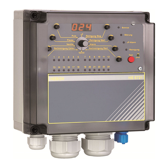
General Description General Description General The HE 5721 FP solenoid valve control system is used for pulse activation of solenoid valves in air pollution control systems. The HE 5721 FP permits numerous controlling and monitoring functions and comprises a differen- tial pressure measuring and control system. -
Page 10: Installation And Housing
The housing is applied with threaded holes 1x M20 x1,5 and 2x M32 x 1,5 for metrical cable glands. Not used holes have to be closed with sealing caps. Power Supply The HE 5721 FP is designed for mains operation at 100 – 240 VAC, 50 to 60 Hz. (Option: 24 VDC) # 371342... -
Page 11: Solenoid Valve Controller
Only pause time control Timer mode Schw. 16, 17 connected Pulse- and pause poti * Terminals 18, 19 connected = release Note: Changes of the jumper configuration become effective after a restart of the device! # 371342 HE 5721 FP... -
Page 12: Inputs
1 change over contact for operating/malfunction message (fail-safe- circuit) 1 normally open contact for cleaning message The inputs and the analog output are not potentially separated ! Provide an external potential separation, if required ! # 371342 HE 5721 FP... -
Page 13: Functions
A signal at the input 'malfunction acknowledgement' resets a valve error message (LED and malfunction relay). When the cause of error has been eliminated, the error message is automati- cally removed. (The condition of a valve is recognized with the next excitation.) # 371342 HE 5721 FP... -
Page 14: Pressure Switch
When the differential pressure increases, the pause time is shortened; when the differential pressure decreases, the pause time is prolonged. The variation of the pause time is not linear. Cleaning is terminated when the differential pressure falls below approx. 5% of the measuring range. # 371342 HE 5721 FP... - Page 15 Additionally, a larger amount of dust per impulse is cleaned if the differential pressure is higher (= higher resistance of filter). For shorter pause times, the capacity of the pneumatic system must be considered. # 371342 HE 5721 FP...
-
Page 16: Delta-P-Extension
For a better accuracy of the adjustment, check the current output 0(4) to 20 mA at terminals 23+ and 24-. Adjustment should be carried out at operational temperature as the sensor can present a temperature drift of up to ± 1 mbar. # 371342 HE 5721 FP... -
Page 17: Front Panel
4 Post Cleaning Start [Nachreinigung Start]: (Lowest threshold) [mbar] 5 Valve [Ventil]: the actual valve number is displayed 6 Post Cleaning Cycles [Nachreinigungszyklen] 7 Valves [Ventile]: number of used valves 8 Pause: pause time 9 Pulse [Puls]: pulse time [s] x.xx # 371342 HE 5721 FP... -
Page 18: System Setup
Pause time in seconds. Format xxx Pause In the mode 'Pause Control': Selection of a characteristic curve. Pulse Pulse time in seconds. Format: x.xx ∆p = 0 Zero point calibration See details in chapter 5.3 # 371342 HE 5721 FP... -
Page 19: Adjusting Aids For Integer Parameters
5 s Ƕ 3 flashing flashing flashing flashing During the adjustment the cleaning process is not interrupted: the cleaning pulse is also displayed. The representation of a valve error is suppressed however during the adjustment. # 371342 HE 5721 FP... -
Page 20: Connecting Diagramm
Connecting Diagramm Connecting Diagramm # 371342 HE 5721 FP... -
Page 21: Technical Data
Hysteresis: ±0.1 % Temperature hysteresis: ± 0.5 % Temp.drift / zero point: ± 0.025 %/K Temp.drift / full-span value: ± 0.01 %/K Settings: ● threshold 'cleanig stop' ● threshold 'cleaning start' ● threshold 'p-alarm' ● p-zero-point # 371342 HE 5721 FP... - Page 22 1 cable gland M20, 1 cable gland M32 12 valves with wire designation and wire end sleeves Cable Connection (Option) 1 cable gland M20, 1 cable gland M32 24 valves with wire designation and wire end sleeves Subject to technical alterations ! # 371342 HE 5721 FP...
-
Page 23: Declaration Of Conformity
Declaration of conformity Declaration of conformity # 371342 HE 5721 FP... - Page 24 Declaration of conformity # 371342 HE 5721 FP...
- Page 25 Declaration of conformity # 371342 HE 5721 FP...
- Page 26 Declaration of conformity # 371342 HE 5721 FP...
- Page 27 Declaration of conformity # 371342 HE 5721 FP...
Need help?
Do you have a question about the HE 5721 FP and is the answer not in the manual?
Questions and answers