
Related Manuals for HESCH HE 5697 MFC


Summary of Contents for HESCH HE 5697 MFC
- Page 1 HE 5697 MFC Multifunctional controller Device description (Translation of the original operating manual) # 321859 | Version 1.4...
- Page 2 HESCH Industrie Elektronik GmbH, Documentation Department Copyrights © Copyright 2019 HESCH Industrie-Elektronik GmbH. All rights reserved. The content including pictures and the design of this device description are subject to copyright pro- tection and other laws for protection of intellectual property. The dissemination or altera- tion of the content of this manual is prohibited.
-
Page 3: Table Of Contents
Service............... . 32 Device description HE 5697 MFC... - Page 4 1 x Ethernet, 1 X RS-485, 1 x Profibus ........50 Device description HE 5697 MFC...
-
Page 5: Foreword
Chapter 10 Technical appendix Description of optional components Target group This device description is intended for qualified electricians that will install, wire, commission and put the HE 5697 MFC multifunctional controller into operation. Device description HE 5697 MFC Version 1.4... - Page 6 Technical appendix I/O card: Converter resolution resolved. 09/2015 / 1.3 Chapter 3 (Relay outputs) Text supplement Control contactor; Chapter 10 (Counter input) Text corrected. 10/2019 / 1.4 Chapter 3 (configuration variations), chapter 10: Technical appendix (IO cards/ communication cards Device description HE 5697 MFC Version 1.4...
-
Page 7: Legal Provisions
Manufacturer HESCH Industrie-Elektronik GmbH, Boschstraße 8, D-31535 Neustadt, Germany Intended use The HE 5697 MFC multifunctional controller is used for switching or continuous control with sequence control and electrical measured value recording. The multifunctional controller can be operated within the usage and ambient conditions ... -
Page 8: Safety Information
Warning of explosive atmosphere! Warning of dangerous electrical voltage! Warning of material damage due to electrostatic charging! Warning of material damage! Note! Indicates possible malfunctions and provides information regarding optimal oper- ating conditions. Device description HE 5697 MFC Version 1.4... - Page 9 All warning notes in these operating instructions are structured in a uniform manner. The pictogram designates the type of danger. SIGNAL WORD! An informative text describes the danger and suggests how it can be avoided. Device description HE 5697 MFC Version 1.4...
-
Page 10: Safety During The Individual Phases Of Operation
Clean soiled contacts using oil-free compressed air or spirit and a lint-free cloth. Material damage due to electrostatic charging! Observe the safety measures according to DIN EN 61340-51/-3 in order to pre- vent electrostatic discharging! Device description HE 5697 MFC Version 1.4... - Page 11 It is only permitted to clean the housing with wet cleaning agents in order to avoid static charging. It is required to clean the device in order to prevent increased dust formation. Device description HE 5697 MFC Version 1.4...
-
Page 12: Device Description
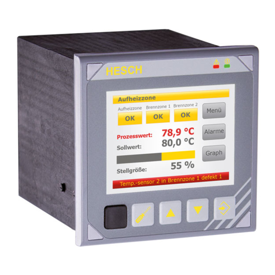
Chapter 3 Device description Device description Overview 3.1.1 Front side Type plate Fig. 3.1: Overview of front side A. Display elements B. Resistive touch screen C. Control elements D. Mini-USB front interface (galvanically isolated) Device description HE 5697 MFC Version 1.4... -
Page 13: Rear Side
A. Slot C (optional and variable), see page 19. B. Slot B (optional and variable), see page 18. C. Slot A (optional and variable), see page 17. D. Power supply slot, see page 16. E. Relay outputs, see page 21. Device description HE 5697 MFC Version 1.4... -
Page 14: Display And Control Elements
Freely assignable control element, see chapter 6 "Software / Programming" on page 28. Freely assignable control element, see chapter 6 "Software / Programming" on page 28. Resistive touch screen Resolution 320 × 240 pixels QVGA Device description HE 5697 MFC Version 1.4... -
Page 15: Technical Data
Climatic Storage -20 °C to +70 °C Transport -20 °C to +70 °C Operation 0 °C to +55 °C Relative humidity Relative humidity 95%, no condensation allowed Air and creepage distances Contamination Class Device description HE 5697 MFC Version 1.4... -
Page 16: Connection Areas
Connection type: 3-pole basic housing; grid dimension 5 B. Transducer supply Connection type: 4-pole basic housing DMC 1.5; grid dimension 3.5 C. USB interface (USB 2.0 host, connector type A) Signal Current no. Power supply Device description HE 5697 MFC Version 1.4... -
Page 17: Slot A - Configuration (Option)
Slot A – Configuration (option) Slot A is variable and can take the following connections: I/O card Fig. 3.4: Slot A: I/O card For information on the I/O card see chapter 10.1 "I/O cards" on page 33. Device description HE 5697 MFC Version 1.4... -
Page 18: Slot B - Configuration (Option)
Slot B – Configuration (option) Slot B is variable and can take the following connections: I/O card Fig. 3.5: Slot B: I/O card For information on the I/O card see chapter 10.1 "I/O cards" on page 33. Device description HE 5697 MFC Version 1.4... -
Page 19: Slot C: Communication Card - Configuration (Option)
1. Profinet + Modbus, see page 48 1 × Profinet CC-A 1 × Modbus TCP (Slave) / 1 × Ethernet (LAN) 1 × RS-485 (Modbus RTU Master) 1 × RS-485 (HPR-Bus Master) Device description HE 5697 MFC Version 1.4... - Page 20 1 × Ethernet (LAN) 1 × RS-485 (Modbus RTU Master) 8. Profibus DP Slave + CAN configuration (Communication card) 1 × Profibus DP Slave 1 × Ethernet (LAN) 1 × CAN Device description HE 5697 MFC Version 1.4...
-
Page 21: Relay Outputs
If a control contactor is connected to a relay output, an RC protective circuit corresponding to the specifications of the contactor manufacturer is required in order to avoid high voltage peaks! Varistor protective circuits are not recommended. Device description HE 5697 MFC Version 1.4... -
Page 22: Connecting External I/Os (Optional)
Connection of several nodes possi- HPR-Bus Only use over short distances Maximum connection of a node CAN-Bus Usage outside the control cabinet possible Connection of several nodes possi- Device description HE 5697 MFC Version 1.4... -
Page 23: Installation
HE 5697 MFC Installation manual Fixing clamps Connectors Note! After receiving the delivery, check it for completeness and obvious defects. In case of a complaint, immediately contact your local HESCH representative. Device description HE 5697 MFC Version 1.4... -
Page 24: Installation
2.2 "Safety during the individual phases of operation" on page 10. The HE 5697 MFC is intended for installation in a control cabinet door or control panel. *Ensure a minimum distance of 20 mm from device front to device front. - Page 25 3. Clamp the fixing clamps on the right and left side of the housing into the brackets. 4. Press both fixing clamps upwards until they engage. 5. Tighten the fixing clamps evenly with a slotted screwdriver. Device description HE 5697 MFC Version 1.4...
-
Page 26: Electrical Commissioning
Only perform the electrical installation in a dead-voltage state. Material damage due to electrostatic charging! Observe the safety measures according to DIN EN 61340-51/-3 in order to pre- vent electrostatic discharging! Note! Only qualified specialists may work on the electronics. Device description HE 5697 MFC Version 1.4... -
Page 27: Supply Voltage
1. Read the supply voltage value off the type plate (there are devices with 100 to 240 V AC and 24 V DC mains voltage). 2. Connect conductors. 3. The multifunctional controller starts when the supply voltage is applied. Boot time: approx. 17 seconds. Device description HE 5697 MFC Version 1.4... -
Page 28: Software / Programming
Ensure that the USB dongle (license key) is inserted in a USB interface of the computer. 2. Start the EasyTool MFC PC software. 3. Load the project. 4. In the menu bar under "Device", select "Data to device". Device description HE 5697 MFC Version 1.4... - Page 29 USB port on the front side of the multifunctional controller, select the "Device (front)" interface and confirm with "OK". If the data transfer was successful, the win- dow is closed. The multifunctional controller will restart automatically. Device description HE 5697 MFC Version 1.4...
-
Page 30: Operation
Chapter 7 Operation Operation Operation is started by applying the supply voltage. The boot time of the multifunctional controller is approx. 17 seconds. Device description HE 5697 MFC Version 1.4... -
Page 31: Controls
The multifunctional controller is operated via the touch screen and the four buttons on the front of the device. All functions are freely programmable and can therefore not be described here. The description of the controls must be made by the creator of the respective program. Device description HE 5697 MFC Version 1.4... -
Page 32: Maintenance And Service
Recycle metals and plastics. Electrical and electronic components should be collected separately and be disposed of accordingly. Properly dispose of printed circuit boards. Service HESCH Industrie-Elektronik GmbH Boschstraße 8 31535 Neustadt Germany Phone: +49 5032 9535-0 Device description HE 5697 MFC Version 1.4... -
Page 33: Technical Appendix
I < 50 µA KTY 11-6 I < 50 µA Accuracy: ≤1K Temperature drift: ≤0.08% / 10K Measuring circuit monitoring: Short circuit, interruption Thermocouple measurement Input type: Voltage Connection type: 2-conductor Input resistance: >10 MΩ Device description HE 5697 MFC Version 1.4... - Page 34 Connection type: 2-conductor Measuring ranges: 0 to 20 kΩ Detection range: Measuring range + 10% Measuring current: tbd. mA Accuracy: ≤0.1% Temperature drift: ≤0.08% / 10 K Measuring circuit monitoring: Overflow detection range Device description HE 5697 MFC Version 1.4...
- Page 35 2-conductor Measuring ranges: 0 to 10 V Detection range: Measuring range +/- 10% Input impedance: type 1.2 MΩ Accuracy: ≤0.1% Temperature drift: ≤0.08% / 10 K Measuring circuit monitoring: Detection range - underflow/overflow Device description HE 5697 MFC Version 1.4...
- Page 36 1. Here the signal evaluation and further processing to an "analogue signal" takes place. Cut-off frequency: 10 kHz Output signal: Impulses / time unit Device description HE 5697 MFC Version 1.4...
- Page 37 I/O card (slot A = A; slot B = B) Fig. 10.1: I/O card electrical connections Interface X_1 Connection type: 4-pole basic housing DMC 1.5; grid dimension 3.5 Analogue output 1 Signal Current no. Voltage output Current output Device description HE 5697 MFC Version 1.4...
- Page 38 Fig. 10.2: Analogue input 1 universal input Fig. 10.3: Analogue input 1 standard signal input Interface X_3 Connection type: 4-pole basic housing DMC 1.5; grid dimension 3.5 Analogue output 2 Signal Current no. Voltage output Current output Device description HE 5697 MFC Version 1.4...
- Page 39 Connection type: 8-pole basic housing DMC 1.5; grid dimension 3.5 Signal Current no. Input/output supply + 24 V external 0 V external Inputs/outputs Input/Output 1 Input/Output 2 Input/Output 3 Input/Output 4 Input/Output 5 Input/Output 6 Device description HE 5697 MFC Version 1.4...
- Page 40 Chapter 10 Technical appendix 10.1.1.9 Connection example Device description HE 5697 MFC Version 1.4...
-
Page 41: I/O Card Type 2
I < 50 µA KTY 11-6 I < 50 µA Accuracy: ≤1K Temperature drift: ≤0.08% / 10K Measuring circuit monitoring: Short circuit, interruption Thermocouple measurement Input type: Voltage Connection type: 2-conductor Input resistance: >10 MΩ Device description HE 5697 MFC Version 1.4... - Page 42 Resistance Connection type: 2-conductor Measuring range: 0 to 20 kΩ Detection range: Measuring range + 10% Measuring current: tbd. mA Accuracy: ≤0.1% Temperature drift: ≤0.08% / 10 K Measuring circuit monitoring:Overflow detection range Device description HE 5697 MFC Version 1.4...
- Page 43 These provide one voltage and one current output. Converter resolution: 12 Bit Linearity: <0.1% Accuracy: <0.2% Temperature drift: ≤0.1% / 10K Cycle time: 50 ms Galvanic isolation: corresponding to category a, see page 16 Device description HE 5697 MFC Version 1.4...
- Page 44 Power consumption: I < 1 A @ 5 V I < 50 mA @ 3.3 V 10.1.2.7 Ambient conditions See chapter 3.3 "Technical data" on page 15. Device description HE 5697 MFC Version 1.4...
- Page 45 I/O card (slot A = A; slot B = B) Fig. 10.6: I/O card electrical connections Interface X_1 Connection type: 4-pole basic housing DMC 1.5; grid dimension 3.5 Analogue output 1 Signal Current no. Voltage output Current output Device description HE 5697 MFC Version 1.4...
- Page 46 Fig. 10.7: Analogue input 1 universal input Fig. 10.8: Analogue input 1 mV input Interface X_3 Connection type: 4-pole basic housing DMC 1.5; grid dimension 3.5 Analogue output 2 Signal Current no. Voltage output Current output Device description HE 5697 MFC Version 1.4...
- Page 47 Connection type: 8-pole basic housing DMC 1.5; grid dimension 3.5 Signal Current no. Input/Output supply + 24 V external 0 V extern Inputs/Outputs Inputs/Outputs 1 Inputs/Outputs 2 Inputs/Outputs 3 Inputs/Outputs 4 Inputs/Outputs 5 Inputs/Outputs 6 Device description HE 5697 MFC Version 1.4...
-
Page 48: Communication Cards
I < 0.1 A @ 3.3 V 10.2.1.4 Ambient conditions See chapter 3.3 "Technical data" on page 15. 10.2.1.5 Electrical connections Ethernet ports XC1 and XC2: RJ-45 Recommended connection cable: Better than Cat5 Device description HE 5697 MFC Version 1.4... - Page 49 Basic housing MC 1.5; grid dimension 3.5 Assembly Signal Current no. RS-485 Port 1 FE (shield connection) Interface Connection type Basic housing MC 1.5; grid dimension 3.5 Assembly Signal Current no. RS-485 Port 2 FE (shield connection) Device description HE 5697 MFC Version 1.4...
-
Page 50: 1 X Ethernet, 1 X Rs-485, 1 X Profibus
Link = LED lights up continuously Data = LED flashes 10.2.2.3 RS-485 interface Interface Connection type Basic housing MC 1.5; grid dimension 3.5 Assembly Signal Current no. RS-485 FE (shield connection) Device description HE 5697 MFC Version 1.4... - Page 51 Notes Device description HE 5697 MFC Version 1.4 • Item number #321859 • 10/2019...
- Page 52 Notes Device description HE 5697 MFC Version 1.4...
Need help?
Do you have a question about the HE 5697 MFC and is the answer not in the manual?
Questions and answers