Sign In
Upload
Manuals
Brands
HESCH Manuals
Controller
HE 5750
HESCH HE 5750 Manuals
Manuals and User Guides for HESCH HE 5750. We have
2
HESCH HE 5750 manuals available for free PDF download: Operating Instructions Manual
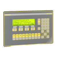
HESCH HE 5750 Operating Instructions Manual (94 pages)
Solenoid valve controller
Brand:
HESCH
| Category:
Controller
| Size: 7 MB
Table of Contents
Table of Contents
4
Legal Provisions
7
Safety Information
8
Symbols and Basic Safety Instructions
8
Signal Words
8
Safety in the Individual Operating Phases
9
Unpack Device
9
Mounting
9
Power Connection
9
Commissioning
10
Troubleshooting
10
Decommissioning
10
Maintenance, Repair and Modification
11
Explosion Prevention
11
Technical Data
12
Sketch of Filter System
13
Glossary
13
Device Description
15
Front View
15
General Description
15
Communication Structure
16
System Setup
16
System Layout
17
Components
18
Master Controller Cabinet
18
Damper Controller Cabinet
18
Valve Controller (Slave Box)
18
HE 1149 Pressure Transmitter, Manifold Pressure Sensor
19
Possible Differential Pressure Sensors
19
Installation and Housing
20
Power Supply
20
Device Dimensions
20
Commissioning
21
Inputs and Outputs (Rear View HE 5750)
21
Standard Assignment of Local Operating Elements
21
Galvanic Isolation
22
Setting the Common Baud Rate in the Can Network
23
Setting the Damper Number (Address)
24
HE 5750 (Master)
24
HE 5750 (Slave)
24
HE 5740 (Damper Controller Boxes)
24
Network Topology
24
Local Operation on the Switch Cabinet
25
Limitation of Local Operation
25
Network Topology Sketch
26
Slaves Per Chamber
26
Slaves Per Chamber
27
Change of Units in 'Smarttool
28
System Start
29
Display and Operating Elements
30
Numeric Keypad and Input Block
30
Function Keys F5-F16
31
Actual System Status F5
31
Alarms F6
33
Info Screen F7
33
Service Screen F2
33
Standby Mode F3 (When Operated with Switch Unit Only)
33
Screen up / Screen down Keys F8 and F16
34
Lamp Test F9
34
Test Functions F10
34
Acknowledging Alarms F11
34
Graphic (Delta-P / Dust Development / Filter Cycle Time) F12
35
Chamber Status F13
35
Isolation Valves F14
36
Chamber Isolation F15
36
Context - Sensitive Keys F1-F4
37
Filter Cycle Times
40
Parameter
41
Accessing Parameter Menu
41
Parameter Groups
41
Passwords
41
Parameter Table (Parameter Groups 1-6)
42
Parameter Description (Parameter Groups 1-6)
43
Parameter Table (Parameter Groups 7-12)
48
Parameter Description (Parameter Groups 7-12)
49
Parameter Table (Parameter Groups 13-19)
52
Parameter Description (Parameter Groups 13-19)
54
Commands
59
Command Sources
59
Command Diagram
60
Local Operation / Remote Control
61
Alarm and Error Messages
62
System Start
62
Alarm Screens
63
Alarms of Current Operation
65
Sensor Error
66
Pressure Error
66
Damper Error
67
Valve Controller Bus Error
67
Valve Error
68
Valve Controller Manifold Pressure-Sensor Error
68
Valve Controller Isolation Valve-Error
68
Valve Controller Dust Sensor-Error
69
Valve Controller Tank Pressure-Error (Sensor Ok)
69
Valve Controller Valve Error Dust too High
69
Valve Controller Dust too High
69
Hopper Level
69
Valve Controller Isolation Valve Locked
69
Communication
70
Master-Slave CAN Communication
70
Data Direction Plc -> He 5750
71
Data Direction He 5750 -> Plc
73
Diagnosis He 5750 at Plc
75
Solenoid Valve Controller
78
Description
78
Supply He 5724
78
Status Diagnosis He 5724
79
Terminals and Jumpers
80
Can Wiring and Bus Termination
81
Pre-Pressure Control
82
Options
83
Central Dust Monitoring
83
Reset Dust Valves
85
He 5750 Switch Unit
86
Safety Information
86
Device Description of Switch Unit
87
Display and Operating Elements
91
Technical Data of Switch Unit
92
Pin Assignment
93
Maintenance and Service
94
Advertisement
HESCH HE 5750 Operating Instructions Manual (89 pages)
Solenoid Valve Control
Brand:
HESCH
| Category:
Controller
| Size: 5 MB
Table of Contents
Table of Contents
3
Legal Regulations
6
Safety Guidelines
7
Symbols and Basic Safety Guidelines
7
Safety During the Individual Operating Phases
8
Glossary
11
Filtersystem Skizze
11
Device Description
13
Display
13
General Description
13
System Setup
14
Communication Structure
14
System Layout
15
Components
16
Installation and Housing
18
Network Supply
18
Device Dimensions
18
Commissioning
19
In- and Outputs (Rear Display HE 5750)
19
Standard Assignment
19
Galvanic Isolation
19
Setting of the Common Baud Rate in the CAN Network
20
Setting of the Node No. (Address)
21
Limitation of Local Operation
22
Local Control at Control Cabinet
22
Network Topology Diagramm
23
System Start
25
Display and Operating Keys
26
Numeric Keypad and Input Block
26
Function Keys F5 - F16
27
Context-Sensitive Keys F1 - F4
32
Filter Time of Circulation
35
Passwords
36
Parameter
36
Open Parameter Menu
36
Parameter Groups
36
Parameter
37
Parameter Table (1/3)
37
Parameter Table (2/3)
38
Name System Min Max Unit
39
Parameter Table (3/3)
39
Chambers 8 1
42
Controller/Chamber 1 1
42
Manifolds/Controller
42
System Parameters
42
Valves on 1. Slave
42
Valves/Chamber
42
Damper Control
43
Dust Detectors/Chamber
43
Hopper Level
43
Isolation Valves/Slave
43
Valves in 1. man
43
Valves in 1. Manifold 16 1
43
Language
44
Local Operation 2
44
Synchro Time -1
44
Baud Rate COM
45
Device Address 1 1
45
Interfaces 3
45
Modbus Parity
45
Modem Interface
45
PLC Interface
45
Profibus Node ID
45
60000 Ms
46
Chamber Sequence
46
Cleaning
46
Manuell Cleaning Mode
46
Operating Mode
46
Valve Control 4
46
Valve Sequence
46
36000 S
47
Manifold Filling Time
47
Pressure Switch Function
47
System Pressure on
47
Drain Valve Pause
48
Drain Valve Pulse Ms
48
Drain Valves
48
Start/Stop Function
48
System Pressure off
48
Command Sources
64
Commands
64
Command Flowchart
65
Local/Remote Operation
66
Alarm and Error Messages
67
System Start
67
Alarm Screens
68
Alarms of Ongoing Operation
69
Communication
74
Master - Slave CAN Communication
74
Data Direction PLC → HE 5750
76
Data Direction HE 5750 → PLC
77
Diagnosis HE 5750 at PLC
79
Description
81
Solenoid Valve Control
81
State Diagnosis HE 5724
81
Supply HE 5724
81
Terminals and Jumpers
82
CAN Wiring and Bus Connection
83
Technical Data HE 5750
84
Central Dust Monitoring
86
Options
86
Reset Dust Valves
88
Maintenance and Service
89
Advertisement
Related Products
HESCH HE 5422 MR
HESCH HE 5697 MFC
HESCH HE 5733
HESCH HE 5721 FP
HESCH HE 5709 Basic
HESCH HE 5713 Basic
HESCH HE 5712 Compact
HESCH HE 5731 Modular
HESCH HE 5710
HESCH HE 5711
HESCH Categories
Controller
Control Unit
Control Systems
Transmitter
Transducer
More HESCH Manuals
Login
Sign In
OR
Sign in with Facebook
Sign in with Google
Upload manual
Upload from disk
Upload from URL