
Related Manuals for HESCH HE 5733


Summary of Contents for HESCH HE 5733
- Page 1 HE 5733 Shaker filter controller Operating instructions (Translation of Original German version) #373511 | Version 1.0...
- Page 2 Published by: AXXERON HESCH electronics GmbH, documentation department Copyrights © Copyright 2023 AXXERON HESCH electronics GmbH. All rights reserved. The content including pictures and the design of these operating instructions are subject to copyright protection and other laws for the protection of intellectual property.
- Page 3 Document history Date / Version Description / Author 16/11/2023 / 1.0 First version / Bg HE 5733 Operating Instructions #373511 | Version 1.0...
-
Page 4: Table Of Contents
Screw closures ..........................17 ..........................18 PENING THE DEVICE ..........................19 OUNTING THE DEVICE DEVICE OVERVIEW ..........................20 5.1.1 HE 5733 shaker filter controller ..................... 20 5.1.2 Differential pressure module ......................20 ELECTRICAL COMMISSIONING ........................ 21 ............................22 IRING DIAGRAM ........................22... - Page 5 4.0 .................... 40 ARAMETRISATION VIA ONTROLS ..........................41 FFSET FOR ZEROING ........................42 ESET OF DEFAULT SETTINGS DIFFERENTIAL PRESSURE MEASUREMENT ..................43 ERROR MESSAGES ..........................44 MAINTENANCE AND SERVICE ......................46 HE 5733 Operating Instructions #373511 | Version 1.0...
-
Page 6: Legal Provisions
Legal Provisions Manufacturer AXXERON HESCH electronics GmbH, Boschstraße 8, 31535 NEUSTADT, GERMANY Intended use The shaker filter controller is a compact controller consisting of an I/O unit and an operating unit. The shaker filter is used for separating dust from raw gases. -
Page 7: Safety Information
Indicates a potentially hazardous medium risk situation, which, if not avoided, could result in death or serious injury. CAUTION! Indicates a hazardous low risk situation, which, if not avoided, could result in minor or moderate injury. HE 5733 Operating Instructions #373511 | Version 1.0... -
Page 8: Safety In The Individual Operating Phases
Observe the safety measures according to DIN EN 61340-51/-3 to avoid electrostatic discharge! Power Connection! The electrical cables must be laid according to the respective national regulations (in Germany VDE 0100). The measuring cables must laid separately from the power lines. HE 5733 Operating Instructions #373511 | Version 1.0... - Page 9 Switch off the power supply on all poles if the device is to be decommissioned. Secure the device against being unintentionally switched on! If the device is connected to other devices and/or equipment, consider the impacts and take appropriate precautions before switching it off. HE 5733 Operating Instructions #373511 | Version 1.0...
-
Page 10: Device Identification And Name Plates
Use in zone 22 for dust IP65 Protection type: Dust-tight and protected against water jets 2.4.2 Name plates HE 5733 with measuring range 0…50 mbar HE 5733 with measuring range 0…100 mbar HE 5733 Operating Instructions #373511 | Version 1.0... -
Page 11: Special Regulations
The ATEX approval remains valid only, if the installation is carried out professionally in compliance with the protection class indicated in the device identification. Note! Close cable glands that are not needed with a locking bolt and housing bores with blanking plugs. HE 5733 Operating Instructions #373511 | Version 1.0... -
Page 12: Technical Data
(fan contactor, shaker contactor): Type of output: potential-loaded semiconductor switch with flyback diode 24 V DC Switching voltage: 200 mA, short-circuit proof Switching current: Potential: no galvanic isolation HE 5733 Operating Instructions #373511 | Version 1.0... - Page 13 Galvanic isolation: Rotating field detection External conductor L1, L2, L3 (400 V AC / 50 Hz, Connection: -10% / +20% Potential: galvanically isolated via optocoupler Interface for software update USB/TTL interface adapter: #58513007 HE 5733 Operating Instructions #373511 | Version 1.0...
- Page 14 .: max. 0.75 mm² with wire end ferrule 3 x cable terminal screw connection M25 (supply, fan, shaker) 1 x cable terminal screw connection M20 Cable inlet: (dp-alert, enable) 1 x cable terminal screw connection M16 (cover switch) HE 5733 Operating Instructions #373511 | Version 1.0...
-
Page 15: Mounting
2.4 Device identification and name plates. Dimensions The dimensions including the cable glands are 271 × 170 × 120 mm. Dimensions HE 5733 HE 5733 Operating Instructions #373511 | Version 1.0... -
Page 16: Torques
Operating instructions (#373511) Note! Check the delivery for completeness and obvious defects after receipt. Please contact your service representative at AXXERON HESCH electronics GmbH immediately in the event of a complaint. Torques Note! When installing the device, you must strictly observe the torques listed in the following tables. -
Page 17: Cable Glands
4.3 g M25 × 1.5 30 mm 13 mm 12 mm 4.0 mm 3.0 Nm 6.6 g M32 × 1.5 37 mm 15 mm 14 mm 5.5 mm 5.0 Nm 12.0 g HE 5733 Operating Instructions #373511 | Version 1.0... -
Page 18: Opening The Device
Open the housing cover to the left up to an angle of 105° (see step 3 in Figure 3). Optionally, the housing cover can be closed with 4 screws to prevent the device from unauthorised access (for further information, please contact the service of AXXERON HESCH electronics GmbH, see chapter 12 Maintenance and Service). -
Page 19: Mounting The Device
The position of the boreholes are identical for every housing. Figure 4 shows an exemplary housing. Back of the housing Note! Alternative: wall mounting with wall brackets. For more information, please contact the service of AXXERON HESCH electronics GmbH (see chapter 12 Maintenance and Service). HE 5733 Operating Instructions #373511 | Version 1.0... -
Page 20: Device Overview
Device overview The HE 5733 is available in different versions. On one hand with a measuring range of 0…50 mbar (#573311002D50)) and on the other with a measuring range of 0…100 mbar (#573311002D60) (see name plate in chapter 2.4 Device identification and name plates). -
Page 21: Electrical Commissioning
Note! Please connect the cables to the cable screw connections properly. Note! The temperature limitations specified for the use of the device must be complied with before and during operation. HE 5733 Operating Instructions #373511 | Version 1.0... -
Page 22: Wiring Diagram
In tab EPLAN under section EPLAN Wiring diagrams, you can find the right diagram for your device. Supply voltage / Operation Note! Please observe the name plate in order to apply the correct supply voltage. Inside of HE 5733 dp-module RJ-45 modular connector for operating unit Relay outputs (RUN/ERR, dp-ALERT) Digital inputs... -
Page 23: Inputs
Opening the device a) Apply the supply voltage 400 V AC. b) Connect the PE conductors. The 7-segment display shows HE 5733 as scrolling text and the device carries out an LED test. Each LED lights up shortly once. Inputs 6.3.1 Digital inputs... -
Page 24: Outputs
The dp-module has an analogue current output and an analogue voltage output. The current differential pressure is signalised via a 0(4)…20 mA & 0…10 V signal, which is not galvanically isolated. 0…10 V 0(4)…20 mA HE 5733 Operating Instructions #373511 | Version 1.0... -
Page 25: Assembly Of Measuring Hose Onto Pressure Connection
Connect hose Insert hose with 6 mm outer diameter into the connection. Disconnect hose 1. Press the blue retaining ring to open the lock. 2. Pull the hose out of the connection. HE 5733 Operating Instructions #373511 | Version 1.0... -
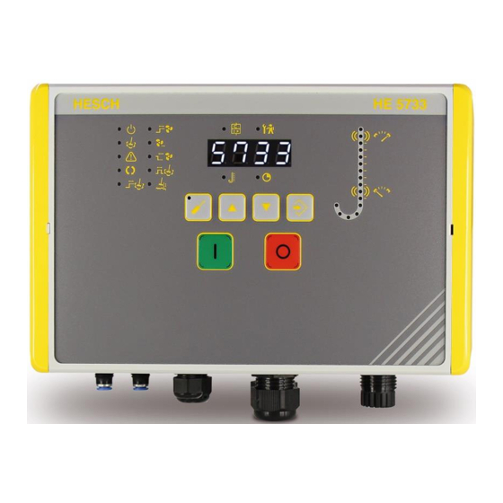
Page 26: Display And Operating Elements
Keys and LED Display and Operating Elements external Symbols/Displays Meaning External Operation signal Cleaning active Alarms active Automatic cleaning active Pre-warning time for automatic cleaning Start-up time of fan Overrun time of fan HE 5733 Operating Instructions #373511 | Version 1.0... - Page 27 confirming the displayed value 7-segment display Normal operation: current differential pressure Parametrisation mode: parameter values Alarm information ON key Switching the system on OFF key Switching the system off HE 5733 Operating Instructions #373511 | Version 1.0...
- Page 28 LED ERROR Is coupled to the alarm/operation relay of the software Lights up, when the relay is de-energised (alarm) goes out, when the relay is energised (operation) HE 5733 Operating Instructions #373511 | Version 1.0...
- Page 29 (shaker motor / fan motor). 2 Test switch for releasing / testing the motor protection switches. 3 Switch for resetting or switching the system back on, when the motor protection switch was released. HE 5733 Operating Instructions #373511 | Version 1.0...
-
Page 30: Differential Pressure Column
Alarm dp-Low Alarm Zeroing Differential pressure column During normal operation, the LEDs indicate the differential pressure. During parametrisation mode, the selected parameter value is indicated by the corresponding LED. HE 5733 Operating Instructions #373511 | Version 1.0... -
Page 31: Operation
With the parameter `Malfunction` you can determine, whether the fan stays on after a malfunction (On). In that case, the system keeps running. Or if the fan switches off (Off) and the system stops. HE 5733 Operating Instructions #373511 | Version 1.0... -
Page 32: Cleaning With Differential Pressure Monitoring
cleaning starts as soon as the ‘run-down time of fan’ has run out. the device switches the fan back on, as soon as the ‘settling time of dust’ has run HE 5733 Operating Instructions #373511 | Version 1.0... -
Page 33: Time-Controlled Cleaning
If the digital input is deactivated (low), all outputs are switched off immediately. If the digital input is activated again (high), the system is ready for operation. Press the green ON key. The system starts. HE 5733 Operating Instructions #373511 | Version 1.0... -
Page 34: Test & Service
Press the keys UP or DOWN, to select the requested test function (see a.-d.). Output test: relay dp-alert = off Output test: relay RUN / ERROR = off Output test: fan contactor = off Abbreviation for motor protection switch HE 5733 Operating Instructions #373511 | Version 1.0... -
Page 35: Switching The Device Off
Switching the device off Press the OFF key to turn the system off. Disconnect the device from the voltage supply to turn it off. The LEDs and the display go out. HE 5733 Operating Instructions #373511 | Version 1.0... -
Page 36: Parametrisation
** only for controller with differential pressure monitoring The following parameters can be set via EasyTool Controls 4.0 only: Parameter Setting range Default setting 0…9999 Password 0001 Protection against unauthorised parameter changes. HE 5733 Operating Instructions #373511 | Version 1.0... -
Page 37: Overview Of Parameters And Their Leds
Duration of cleaning Cleaning interval Start-up time of fan Run-down time of fan Overrun time of fan Settling time of dust Malfunction Polarity of cover switch dp-parameters dp-offset dp-min. dp-max. dp-measuring range HE 5733 Operating Instructions #373511 | Version 1.0... -
Page 38: Parametrisation With Device Keys
The current value of the parameter is shown in the display. d) Press ENTER. The first digit of the parameter value flashes. Press the keys UP or DOWN to set the requested parameter value. HE 5733 Operating Instructions #373511 | Version 1.0... - Page 39 The parametrisation mode is terminated and you leave the parameter menu. The LED on the PARA key goes out. In order to re-enter the parameter menu, enter the password once again (see steps 4+5 in this chapter). HE 5733 Operating Instructions #373511 | Version 1.0...
-
Page 40: Parametrisation Via Easy Tool Controls 4.0
To change the parameter values, double-click on the current parameter value. Now, you can either enter the new value manually or click on the up and down arrows until the requested value is reached. Parameter setting via EasyTool Controls 4.0 HE 5733 Operating Instructions #373511 | Version 1.0... -
Page 41: Offset For Zeroing
Offset. b) Press the keys UP or DOWN separately to set the offset value manually. In this case, step a) is not necessary. Press the ENTER key to confirm the entry. HE 5733 Operating Instructions #373511 | Version 1.0... -
Page 42: Reset Of Default Settings
Press the ENTER key to start entering the password. Set your password using the UP and DOWN keys. After input and confirmation of the last password digit, the controller starts with default settings (see 9.1 Parameter table). HE 5733 Operating Instructions #373511 | Version 1.0... -
Page 43: Differential Pressure Measurement
The current output is scalable via the adjustable measuring range. For example: 0 … 30 mbar ≙ 4 … 20 mA / 0…10 V, 0 … 20 mbar ≙ 4 … 20 mA / 0…10 V HE 5733 Operating Instructions #373511 | Version 1.0... -
Page 44: Error Messages
The High alarm LED The differential pressure exceeds flashes: the set threshold. The Low alarm LED The differential pressure falls flashes: below the set threshold for longer than 5 minutes without reaching the post-cleaning threshold. HE 5733 Operating Instructions #373511 | Version 1.0... - Page 45 The 4 LEDs of the ON key Connect L3 or device is supplied by L1 and L2) rotate clockwise, the 4 check external fuse LEDs of the OFF key rotate counter-clockwise: HE 5733 Operating Instructions #373511 | Version 1.0...
-
Page 46: Maintenance And Service
Dispatch metals and plastics for recycling. Electrical and electronic components must be collected separately and disposed of properly. Dispose of equipped circuit boards properly. AXXERON HESCH electronics GmbH Boschstraße 8 31535 NEUSTADT GERMANY Phone: +49 5032 9535-0 Web: www.hesch-automation.com Email: info@hesch.de HE 5733 Operating Instructions #373511 | Version 1.0...
Need help?
Do you have a question about the HE 5733 and is the answer not in the manual?
Questions and answers