
Related Manuals for HESCH HE 5750


Summary of Contents for HESCH HE 5750
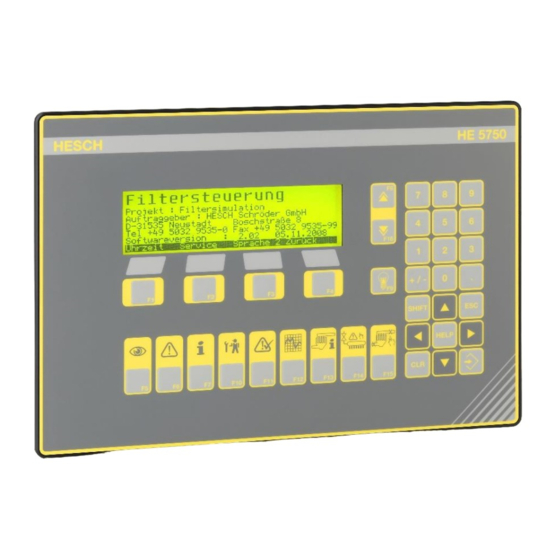
- Page 1 HE 5750 Solenoid valve controller Operating instructions (Translation of Original German version) #371627...
- Page 2 Published by: HESCH Industrie-Elektronik GmbH, Documentation Department Copyrights © Copyright 2022 HESCH Industrie-Elektronik GmbH. All rights reserved. The content including pictures and the design of these operating instructions are subject to copyright protection and other laws for the protection of intellectual property. The operating instructions may only be distributed as a complete document and only with reference to the source.
- Page 3 Document history Date / Version / Software version Description / Author 2021-06-21 / 1.0 / 2.16 Operating instructions written based on HE 5750 with option central dust sensor (#371617, version from 2020-01-22, software version 2.15) Chapter HE 5750 switch unit added 2021-07-21 / 1.1 / 2.17...
-
Page 4: Table Of Contents
ETTING THE COMMON BAUD RATE IN THE NETWORK ) ...................... 24 ETTING THE DAMPER NUMBER ADDRESS 7.5.1 HE 5750 (Master) .......................... 24 7.5.2 HE 5750 (Slave) ..........................24 7.5.3 HE 5740 (Damper controller boxes)....................24 7.5.4 Network topology .......................... 24 .................... - Page 5 Valve controller valve error dust too high ................. 69 11.3.11 Valve controller dust too high ....................69 11.3.12 Hopper level..........................69 11.3.13 Valve controller isolation valve locked ..................69 COMMUNICATION ..........................70 12.1 CAN C ......................70 ASTER LAVE OMMUNICATION HE 5750 Operating Instructions #371627 | Version 1.1...
- Page 6 12.2 PLC -> HE 5750 ........................ 71 ATA DIRECTION 12.3 HE 5750 -> PLC ........................ 73 ATA DIRECTION 12.4 HE 5750 PLC ........................75 IAGNOSIS SOLENOID VALVE CONTROLLER ......................78 13.1 ............................. 78 ESCRIPTION 13.2 HE 5724 ............................78 UPPLY 13.3...
-
Page 7: Legal Provisions
1 Legal Provisions Manufacturer HESCH Industrie-Elektronik GmbH, Boschstraße 8, 31535 NEUSTADT, GERMANY. Intended use The device is exclusively intended for the use as measuring and testing device in technical systems. The device can be operated within the approved ambient conditions (see chapter 3 Technical Data without impairment of its safety. -
Page 8: Safety Information
Indicates a potentially hazardous medium risk situation, which, if not avoided, could result in death or serious injury. CAUTION! Indicates a hazardous low risk situation, which, if not avoided, could result in minor or moderate injury. HE 5750 Operating Instructions #371627 Version 1.1... -
Page 9: Safety In The Individual Operating Phases
The electrical connection takes place according to the wiring diagrams / wiring images of the respective device. HE 5750 Operating Instructions #371627 | Version 1.1... -
Page 10: Commissioning
The device must be protected against unintended operation. If the device is linked to other devices and/or equipment, consider the impacts and take appropriate precautions before switching it off. HE 5750 Operating Instructions #371627 Version 1.1... -
Page 11: Maintenance, Repair And Modification
Except for the devices with EX declaration of conformity! For these EX devices, the information in the associated declaration of conformity and the respective national regulations for setting up electrical systems in potentially explosive areas must also be taken into account. HE 5750 Operating Instructions #371627 | Version 1.1... -
Page 12: Technical Data
Via plug / screw-on terminals (max. diameter 2.5 mm²) - 20 °C…+ 70 °C Storage at 0 °C…+ 50 °C Operation at Relative humidity 75% relative humidity permanently, non-condensing Subject to technical changes without notice! HE 5750 Operating Instructions #371627 Version 1.1... -
Page 13: Sketch Of Filter System
The differential pressure is reviewed regarding a mini- mum value at the same time. If the value falls below this, it is assumed that there is no fan operation and cleaning will not continue. HE 5750 Operating Instructions #371627 | Version 1.1... - Page 14 In connection with the operating mode partial cycle the valves can be individually processed. Drain valves The control supports the drain valves at the local manifold. Parameter 4.14 to 4.16 HE 5750 Operating Instructions #371627 Version 1.1...
-
Page 15: Device Description
Display and operating elements 5.2 General Description The system controller HE 5750 is the central unit in a CAN based network of the cleaning controller for industrial hose filters. The central control communicates with the decentralised valve control units HE 5724 and the damper control units HE 5740 via the industrial CAN bus. -
Page 16: Communication Structure
Communication structure 5.3 Communication structure The central controller HE 5750 is the master in the CAN bus system of the filter controller system. A PROFIBUS-DP or a ModBus interface are available for the process control. Alternatively, a parallel interface for the binary signal exchange is available. However, the complete signal list can only be accessed via the serial interfaces. -
Page 17: System Layout
5.5 System layout Distributed process Master controller HE 5750 Profibus (Ethernet) control Modbus TCP Modbus RTU RS485 / Modem RS232) RS232 Parallel interface Remote with software SmartTool Local control Damper Valve controller Extra I/O Slaves Differential pressure Manifold Compressed air... -
Page 18: Components
600 mm × 600 mm × 210 mm (W × H × D) Weight: 22.8 kg System designation 5.6.3 Valve controller (Slave Box) 380 mm × 300 mm × 155 mm (W × H × D) Weight: 7.5 kg System designation HE 5750 Operating Instructions #371627 Version 1.1... -
Page 19: He 1149 Pressure Transmitter, Manifold Pressure Sensor
151 mm × 160 mm × 61 mm (W × H × D) HE 5422 MR (with measuring hose cleaning) 200 mm × 150 mm × 100 mm (W × H × D) HE 5750 Operating Instructions #371627 | Version 1.1... -
Page 20: Installation And Housing
The device has got a network filter. In case of transient interference voltages, an additional external line filter may be required. The line filter is not included in the standard delivery, but can be ordered from HESCH Industrie-Elektronik GmbH. 6.1 Power supply The controller requires 24 V DC. -
Page 21: Commissioning
7 Commissioning 7.1 Inputs and outputs (rear view HE 5750) 20…24…30 V, 0.5 A 4×4 to 20 mA 8× max. 24 V, 300 mA 8× max. 24 V external supply (16, 18) external supply Inputs and outputs 7.2 Standard assignment of local operating elements... -
Page 22: Galvanic Isolation
7.3 Galvanic isolation „Digital Output“ and “Digital Input“ need a separate supply. Galvanic isolation HE 5750 Operating Instructions #371627 Version 1.1... -
Page 23: Setting The Common Baud Rate In The Can Network
Basically the rule is: only as quick as necessary, not as quick as possible. The default setting is 50 kBd, Master setting Master setting Slave setting: Slave setting: Network extension: Baud rate [kBaud] Network extension [m] 1200 Network extension: HE 5750 Operating Instructions #371627 | Version 1.1... -
Page 24: Setting The Damper Number (Address)
7.5 Setting the damper number (address) 7.5.1 HE 5750 (Master) The address is preset to 43. The LSB is on the left. 7.5.2 HE 5750 (Slave) The permissible scope of address is between 1 and 32. The address is set with the two rotary coding switches S2 and S3. -
Page 25: Local Operation On The Switch Cabinet
(remote operation, remote control = On). This limitation can only be reversed via the operator level or via ‘SmartTool’. After expiration of the ‘Remote timeout’, the keyboard operation is unlocked again too, in case of an interruption of the connection to the process control. HE 5750 Operating Instructions #371627 | Version 1.1... -
Page 26: Network Topology Sketch
7.8 Network topology sketch 7.8.1 1 Slaves per chamber Network topology with 1 slaves per chamber HE 5750 Operating Instructions #371627 Version 1.1... -
Page 27: Slaves Per Chamber
7.8.2 2 Slaves per chamber Network topology with 2 slaves per chamber HE 5750 Operating Instructions #371627 | Version 1.1... -
Page 28: Change Of Units In 'Smarttool
Also the alarm thresholds must have the correct pressure unit, except for indication of alarm threshold in percent %. Screen in ‘SmartTool’ for changing the units Pound per square inch Inches of water gauge HE 5750 Operating Instructions #371627 Version 1.1... -
Page 29: System Start
CAN management 3. Sending parameters 4. Check Actual system status -Cleaning status -Actual chamber / valve - Delta-p symbol Actual system status - Delta-p measuring value - System pressure End of start-up routine HE 5750 Operating Instructions #371627 | Version 1.1... -
Page 30: Display And Operating Elements
8 Display and operating elements HE 5750 Display and operating elements F1-F4 context keys F5-F16 Fix function Numeric keypad Input block 8.1 Numeric keypad and input block Additional functions, setting possibilities or branches are offered on the individual screens. Function Press the ENTER key to accept an entry. -
Page 31: Function Keys F5-F16
Cleaning status Cleaning message Last active valve Delta-p symbol Cleaning cycle Delta-p Delta-p symbol Upper threshold Lower threshold Clea- ning Cleaning cycle Cleaning status and cleaning cycle HE 5750 Operating Instructions #371627 | Version 1.1... - Page 32 There are alarms in hold position that are no longer applied. Display settings In this display the arrow keys have the following functions: Keys Function (keep pressed!) Reducing brightness Increasing brightness Reducing contrast Increasing contrast HE 5750 Operating Instructions #371627 Version 1.1...
-
Page 33: Alarms F6
The switch unit switches the currently active HE 5750 Master controller into standby mode and activates the second HE 5750 as new Master controller (see chapter 15.2 HE 5750 switch unit). HE 5750 Operating Instructions #371627 | Version 1.1... -
Page 34: Screen Up / Screen Down Keys F8 And F16
8.2.9 Acknowledging alarms F11 Function Display Current alarms are deleted. This The current display does not change. key has the same function as the Alarm Acknowledge button installed at the control cabinet. HE 5750 Operating Instructions #371627 Version 1.1... -
Page 35: Graphic (Delta-P / Dust Development / Filter Cycle Time) F12
Navigation with F8 and F16 or with the arrow keys The dust sensor status is called up with F3. This status indicated the dust content in the clean gas line in HE 5750 Operating Instructions #371627 | Version 1.1... -
Page 36: Isolation Valves F14
8.2.13 Chamber isolation F15 Function Display Chambers are deleted from the cleaning process. The valves are not activated anymore. If available, dampers are closed. HE 5750 Operating Instructions #371627 Version 1.1... -
Page 37: Context - Sensitive Keys F1-F4
(navigation line) in the various screens displays the available accesses and branches. The respective function is started by pressing the corresponding keys F1 to F4. Navigation Navigation line line Context-sensitive keys F1-F4 HE 5750 Operating Instructions #371627 | Version 1.1... - Page 38 status Profibus communication by pressing the F8 / F16 key Alarm screen F6 Current alarms and alarm protocols are displayed. Switching display with F6 key. Acknowledge Back Acknowledge alarm Back HE 5750 Operating Instructions #371627 Version 1.1...
- Page 39 Change the decimal position. Change the value. Alternatively via numeric keypad. Pressing ENTER to confirm the new value. Pressing ESC cancels the input. F4 key cancels the input and switches to previous level. HE 5750 Operating Instructions #371627 | Version 1.1...
-
Page 40: Filter Cycle Times
At the same time an indication appears in the process data image of the controller. The cycle time is formatted as fixed point number in minutes with one position after decimal point. Example: Cycle time 37 => 3.7 minutes = 3 minutes und 7*6 seconds = 3:42 minutes HE 5750 Operating Instructions #371627 Version 1.1... -
Page 41: Parameter
Controller keyboard Service-PC and software ‘SmartTool’ Process level Note! Operating instructions for ‘SmartTool’ can be ordered from HESCH. 9.3 Passwords The parameter values are protected by four different password levels against unauthorised modification. 4 = HE5750 programme level... -
Page 42: Parameter Table (Parameter Groups 1-6)
Chamber cleaning 0 (Off) Cycles Technician Background cleaning 0 (Off) Technician BG cleaning unit 0 (valves) 0 (valves) 2 (cycles) Technician BG cleaning time 1440.0 Minutes Technician BG cleaning threshold 900.0 mbar Technician HE 5750 Operating Instructions #371627 Version 1.1... -
Page 43: Parameter Description (Parameter Groups 1-6)
(analogue value or switch sensor). The signals are handled internally as ‘Switched OR’. 1.9 Isolation valves / Slave A valve controller can switch two isolation valves for 2 manifolds. HE 5750 Operating Instructions #371627 | Version 1.1... - Page 44 3.3 Baud rate COM1 (RS232) If the modem was selected, COM1 is automatically used with 9.6 kbaud, even if the parameter has another value. HE 5750 Operating Instructions #371627 Version 1.1...
- Page 45 Pause time for the second set of control times. This pause time is used for ‘BG cleaning’, ‘manual cleaning’ and ‘post cleaning’. If 0 is entered here, the pause time of the first set is used. HE 5750 Operating Instructions #371627 | Version 1.1...
- Page 46 1st Slave*). If this assignment is not complied with, it is possible that not all valves are cleaned. 5.2 Parallel chambers With a continuous linking of the parallel chambers (parameter parallel chambers 1...24) the maximum number of parallel chambers is limited. HE 5750 Operating Instructions #371627 Version 1.1...
- Page 47 6.6 Background cleaning threshold A value close to zero. If the delta-p value is even smaller, it is assumed that the system is switched off and no background cleaning takes place. HE 5750 Operating Instructions #371627 | Version 1.1...
-
Page 48: Parameter Table (Parameter Groups 7-12)
900.0 Technician 12.5 Dust 49 (No) Technician 12.6 Delta-p Filter 0 (Off) 0 (Off) Technician 12.7 Flow rate filter 0 (Off) 0 (Off) Technician 12.8 Dust filter 0 (Off) 0 (Off) 99.9 Technician HE 5750 Operating Instructions #371627 Version 1.1... -
Page 49: Parameter Description (Parameter Groups 7-12)
Slave. Valve in 1. Manifold = valve in 1. manifold Sl.2) Depending on the wiring of the isolation valves at the local pressure manifolds. 1 Virtual Semi-Offline - Mode 2. True Semi-Offline - Mode HE 5750 Operating Instructions #371627 | Version 1.1... - Page 50 Period for the service related to the cleaning cycles. 10 Autostart / Timeout 10.1 System start Default causes the system to restart without history. ‘Actual‘ takes over the operation of the most recently saved position. HE 5750 Operating Instructions #371627 Version 1.1...
- Page 51 (process value) or the unfiltered value (field value) is transmitted. 12.8 Dust filter The process signal is equipped with a low-pass filter first order. This value is displayed and internally processed. HE 5750 Operating Instructions #371627 | Version 1.1...
-
Page 52: Parameter Table (Parameter Groups 13-19)
15.49 Cleaning factor 48 1000 Technician Pre-pressure control 16.1 Type of control 0 (Off) 0 (Off) 3 (ext. nominal Technician value) 16.2 Type of valves 0 (NC) 0 (NC) 2 (control Technician valve) HE 5750 Operating Instructions #371627 Version 1.1... - Page 53 999.9 Technician 18.5 Dt1-part 999.9 Technician 18.6 Proportional pause Technician 18.7 Controller modificat. Technician 18.8 Controller maximum 900.0 mbar Technician Extra -Only via ‘SmartTool’ 19.1 LCD contrast Customer 19.2 LCD brightness Customer HE 5750 Operating Instructions #371627 | Version 1.1...
-
Page 54: Parameter Description (Parameter Groups 13-19)
Yes: alarm is held and requires an acknowledgement. 13.14 Fail-Safe Logic value of alarm messages. No: high for active alarms Yes: low for active alarms Applies also for signal level in data communication 14 Dust monitoring HE 5750 Operating Instructions #371627 Version 1.1... - Page 55 The first and the last chambers have mostly a higher dust load. A higher cleaning performance can be assigned to individual chambers (and divisions) by cleaning factors. HE 5750 Operating Instructions #371627 | Version 1.1...
- Page 56 16.2 Type of valve Using the control output for the central isolation valve (HE 5750 digital output DO7). 0 (NC): Isolation valve “normally closed”, isolation valve opens as soon as control voltage is applied.
- Page 57 To achieve a continuous cleaning, the pause time between two valve triggerings varies, depending on the current filter status. Influencing variables are either only the differential pressure or additionally also the air flow (depending on the selected settings). 18.1 Maximum Pause HE 5750 Operating Instructions #371627 | Version 1.1...
- Page 58 If the differential pressure exceeds the limit value Controller Maximum, the controller is stopped and cleaned with min. pause time (= max. speed). 19 Extras (only via SmartTool) 19.1 LCD contrast 19.2 LCD brightness HE 5750 Operating Instructions #371627 Version 1.1...
-
Page 59: Commands
10 Commands 10.1 Command sources Command sources (acc. to priority) 1. SIO Serial interface RS232 2. Connection process control Profibus command or Parallel interface 3. Local operating elements HE 5750 Function keys 4. Local operating elements Profibus Parallel interface commands... -
Page 60: Command Diagram
10.2 Command diagram Commands Start Cleaning Permanent signal (release, enable) Stop Permanent signal Emergency stop Permanent signal Reaction Valve triggering Current cycle Current cycle is cancelled is terminated Damper controller Command diagram HE 5750 Operating Instructions #371627 Version 1.1... -
Page 61: Local Operation / Remote Control
The functions ‘Local Operation’ and ‘Remote Operation’ are independent from each other. It is possible to lock the local operating elements without deactivating the key operation and vice versa. PLC-Site Control Modbus Profibus parallel Digital inputs Local operation Local operation / remote control HE 5750 Operating Instructions #371627 | Version 1.1... -
Page 62: Alarm And Error Messages
-CAN wire not terminated. -wrong node ID set. -no common baud rate. -system description does not correspond to the actual hardware. When operated with HE 5750 switch unit: -CAN wire interrupted when HE 5750 Master controller is started. -Master controller in Standby. -
Page 63: Alarm Screens
- system description does not correspond to the actual hardware 11.2 Alarm screens A warning triangle in the display indicates pending alarms. Large triangle Current Alarms existing Small triangle Alarm protocol with entries HE 5750 Operating Instructions #371627 | Version 1.1... - Page 64 (A list of all occured alarms sorted acc. to timely appearance). Latest alarms are displayed first. Max. 200 alarms are listed. With F1 individual alarms are acknowledged. Toggling possible between both displays with the F6 key. HE 5750 Operating Instructions #371627 Version 1.1...
-
Page 65: Alarms Of Current Operation
The cleaning process and the connected hardware are monitored regarding errors. Sensoric and actoric are connected at the individual devices. The HE 5910 units shown in Figure 23 are unnecessary components of the controller. HE 5750 solenoid valve controller HE 5910 Parallel interface (option) Raw gas HE 5910... -
Page 66: Sensor Error
- Minimum pressure set too high System pressure Value complies to the highest or - open wire to sensor sensor error lowest limit, HE 5910 unit reports - short circuit at sensor error HE 5750 Operating Instructions #371627 Version 1.1... -
Page 67: Damper Error
11.3.4 Valve Controller Bus Error Error Message Criterion Error cause Ch. 2 Slave 1 Bus No communication with this controller - wire interruption Error - no voltage supply at node -fuse triggered HE 5750 Operating Instructions #371627 | Version 1.1... -
Page 68: Valve Error
- wire interruption 1 wire break open output - valve not connected - isolation valve defect Ch. 5 Isolation valve Output is monitored: short-circuited - wire crushed 2 overcurrent output - isolation valve defect HE 5750 Operating Instructions #371627 Version 1.1... -
Page 69: Valve Controller Dust Sensor-Error
Valve error ‘Valve not Closing’ Ch. 7 Isolation valve A valve does not close and the 1 locked detected manifold is switched off by the isolation valve. The valve can be opened manually with F14 key. HE 5750 Operating Instructions #371627 | Version 1.1... -
Page 70: Communication
Action Valve monitoring Isolation valve 1 open Local test deactivated Current monitoring Scan Error acknowledgement 2. Control time Digital Current valve unsigned char Digital Isolation valve 2 open unsigned char Process data object HE 5750 Operating Instructions #371627 Version 1.1... -
Page 71: Data Direction Plc -> He 5750
12.2 Data direction PLC -> HE 5750 Position Function Data type Bytes Parallel Interface (IN)Bit Commands Digital Filter start unsigned char Filter stop Quick Hold (emergency stop) Alarm reset Requirement Offline cleaning Requirement post-cleaning Requirement forced cleaning Parallel valve triggering locked... - Page 72 Data type Bytes Parallel Interface (IN)Bit Pure gas damper 2 Damper control direction 0 = open 1 = close Isolation valve opening Commands 3 unsigned char Standby request (Redundancy mode) (rising edge) reserved HE 5750 Operating Instructions #371627 Version 1.1...
-
Page 73: Data Direction He 5750 -> Plc
12.3 Data direction HE 5750 -> PLC Position Function Data type Bytes Parallel Interface (Out) Status information part 1 Digital Cleaning activated unsigned char Filter Hold (emergency stop) Offline cleaning activated Cleaning running Post-cleaning running Forced cleaning running Chamber cleaning running... - Page 74 Chamber 2 Data structure as chamber 1 Chamber 24 Data structure as chamber 1 Additional information Offset Offset = 20 +4 x number of chambers Offset+0 Can be configured freely via Smart- Tool Offset+18 HE 5750 Operating Instructions #371627 Version 1.1...
-
Page 75: Diagnosis He 5750 At Plc
12.4 Diagnosis HE 5750 at PLC Position Function Data type Bytes System status used by Profibus SPC3 chip unsigned char EXT_USER_DIAG 1. Header Digital 00 = device specific diagnosis Length = 11 Byte Status Digital invalid parameter data unsigned char... - Page 76 00 = device specific diagnosis Length = 33 Byte Header+1 4 channel analogue input HE 5750 HE 5750 1. Analogue input wire break HE 5750 1. Analogue input short circuit HE5750 2. Analogue input wire break HE 5750 Operating Instructions...
- Page 77 Position Function Data type Bytes HE 5750 2. Analogue input short circuit HE 5750 3. Analogue input wire break HE 5750 3. Analogue input short circuit HE 5750 4. Analogue input wire break HE 5750 4. Analogue input short circuit...
-
Page 78: Solenoid Valve Controller
CAN wire and power supply must be connected. Connection CAN and power supply 13.2 Supply HE 5724 Attention! The applied voltage must correspond to the voltage indicated on the name plate. 1 CAN connection 2 Power supply Supply HE 5724 HE 5750 Operating Instructions #371627 Version 1.1... -
Page 79: Status Diagnosis He 5724
Blinks during CAN bus error. Lights up permanently, when the connection with the Master is established (CAN status "Operational"). Lights up during following errors: Error EEPROM, sensor, isolating valve, valve and CAN bus errors HE 5750 Operating Instructions #371627 | Version 1.1... -
Page 80: Terminals And Jumpers
13.4 Terminals and jumpers CAN bus termination Supply Fuse Valves Dust sensor Pressure sensor Isolation valves Type selection: Analogue sensor Switch sensor Terminals and jumpers HE 5750 Operating Instructions #371627 Version 1.1... -
Page 81: Can Wiring And Bus Termination
CAN bus connectors: Signal Wire Terminal Name CAN-H white white CAN-H CAN-L brown blue CAN-L CAN- green black V-shield Termination: The last bus participant must be terminated. Set switch to position ON. Bus termination HE 5750 Operating Instructions #371627 | Version 1.1... -
Page 82: Pre-Pressure Control
In the process data pool (PDP), the following function codes are available: IN: external pre-pressure nominal value OUT: pre-pressure nominal value OUT: pre-pressure nominal value scaled for external pressure control valve. These codes can be transferred to the process level via 'SmartTool'. HE 5750 Operating Instructions #371627 Version 1.1... -
Page 83: Options
From software version 2.13, the graphic for the filter cycle times is displayed alternately. The filter is described in HE 5750 with additional parameters, in order to give the controller the distance between chamber and sensor as well as ... - Page 84 Dust graph: 18 s, 90 s, 6 min, 30 min., Delta-p: 90 s, 6 min., 30 min., 2 h The recording is stopped in the display, but keeps on running in the background Switching between dust and Delta-p display HE 5750 Operating Instructions #371627 Version 1.1...
-
Page 85: Reset Dust Valves
If the dust valves are disabled (see 14.9 Lock Dust Valve), they can be enabled again by pressing the function keys F1 or F2 in the 'Current Alarms' view. Function keys for resetting the dust valves Reset dust valves via context keys F1 and F2 HE 5750 Operating Instructions #371627 | Version 1.1... -
Page 86: He 5750 Switch Unit
15.2 HE 5750 switch unit The HE 5750 switch unit is optionally available. In a HE 5750 filter controller system with two HE 5750 master controllers, the switch unit switches the CAN Slave periphery to one of the two master controllers each. -
Page 87: Device Description Of Switch Unit
Note! For using the switch unit, software version 2.16 or higher must be installed on the connected HE 5750 Master controllers. The following figure shows the switch unit with name plate and slide-in strips (top and bottom) to designate the connections. - Page 88 It controls the CAN-Bus communication between the HE 5750 Master controller and the corresponding Slaves. If the communication between Master and Slave is interrupted, the CAN Bus is switched to the second HE 5750 in Standby mode. This HE 5750 functions as the Master now.
- Page 89 Distributed process control Switch unit Function sketch of switch unit HE 5750 Operating Instructions #371627 | Version 1.1...
- Page 90 The communication between the switch unit and the HE 5750 Master controller necessary for the switching process, is done via a digital input and output per HE 5750 Master controller. D-Out Switch unit => D-In HE 5750 (M1/M2) 0=Active, 1=Standby D-Out HE 5750 =>...
-
Page 91: Display And Operating Elements
Lights up yellow, while the application of the switch unit runs. It goes off briefly, if a data pack is sent from the PC to the active HE 5750 Master controller (communication). Lights up red in case of initialisation errors (EEProm, etc.) Flashes red, if no CAN bus is connected during start. -
Page 92: Technical Data Of Switch Unit
80 kPa to 106 kPa during transport: 70 kPa to 106 kPa condensed water Not permitted Not permitted max. operating height above sea 2000 m level Subject to technical changes without notice! HE 5750 Operating Instructions #371627 Version 1.1... -
Page 93: Pin Assignment
Pin designation Pin type D_SUB multi-pin connector, 9-pole Aggregate Signal Current no. Case RS-232 Interface Service-UART Pin designation Pin type RJ-10 modular socket Aggregate Signal Current no. + 3.3 V Serial interface TTL HE 5750 Operating Instructions #371627 | Version 1.1... -
Page 94: Maintenance And Service
Dispatch metals and plastics for recycling. Electrical and electronic components must be collected separately and disposed of properly. Dispose of equipped circuit boards properly. HESCH Industrie-Elektronik GmbH Boschstraße 8 31535 NEUSTADT, GERMANY Phone: +49 5032 9535-0 Internet: www.hesch-automation.com Email: info@hesch.de HE 5750 Operating Instructions #371627 Version 1.1...
Need help?
Do you have a question about the HE 5750 and is the answer not in the manual?
Questions and answers