
Related Manuals for Clarke REBEL 55


Summary of Contents for Clarke REBEL 55
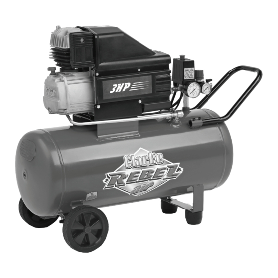
- Page 1 COMPRESSOR MODEL NO: REBEL 55 PART NO: 2323005 OPERATION & MAINTENANCE INSTRUCTIONS LS0512...
-
Page 2: Parts And Servicing
This guarantee does not effect your statutory rights. PARTS AND SERVICING For Parts & Servicing, please contact your nearest dealer, or CLARKE International, on one of the following numbers. PARTS & SERVICE TEL: 020 8988 7400 PARTS & SERVICE FAX: 020 8558 3622 or e-mail as follows: PARTS: Parts@clarkeinternational.com... -
Page 3: Safety Precautions
2. DO NOT operate your compressor with any guards removed. 3. Electrical or mechanical repairs should only be carried out by a qualified engineer. If problems occur, contact your Clarke dealer. 4. Before carrying out any maintenance, ensure the pressure is expelled from the air receiver, and the machine is disconnected from the electrical supply. -
Page 4: Electrical Connections
ELECTRICAL CONNECTIONS WARNING! Read these electrical safety instructions thoroughly before connecting the product to the mains supply. Connect the mains lead to a standard, 230 Volt (50Hz) electrical supply through an approved 13 amp BS 1363 plug, or a suitably fused isolator switch. If the plug has to be changed because it is not suitable for your socket, or due to damage, it should be cut off and a replacement fitted, following the wiring instructions shown below. -
Page 5: Fitting The Handle
ASSEMBLY CAUTION: THE COMPRESSOR IS HEAVY, GET ASSISTANCE WHEN LIFTING OR MOVING THIS COMPRESSOR TO AVOID PERSONAL INJURY. FITTING THE WHEELS Using the axle and nut, secure the wheels as shown. Make sure the wheels are secure before use. FITTING THE SUPPORT FEET Fix the support feet into place as shown using the fixings supplied. -
Page 6: Moving The Air Compressor
MOVING THE AIR COMPRESSOR Before moving the compressor, switch off and disconnect it from the mains power supply. • Always use the handle. • Only move the compressor when it is switched off. • Do not lift by (or put strain on) fittings, valves or hoses. •... -
Page 7: Attaching Air Tools
Add oil until the oil level is between the min and max marks on the dipstick. • Only use SAE40 compressor oil, available from your Clarke dealer. ATTACHING AIR TOOLS WARNING: BEFORE CONNECTING ANY AIR TOOLS, MAKE SURE YOU HAVE READ ANY INSTRUCTIONS SUPPLIED WITH THE TOOL, ALSO ENSURE THAT THE TOOL IS COMPATIBLE WITH THE COMPRESSOR AND HOSE SPECIFICATIONS. -
Page 8: Operation
OPERATION If the compressor has not been used for 24 hours or more, open the drain valve in the tank to drain any condensate which may have accumulated. See page 10. 1. Insert the plug into the power socket and switch on the power. 2. -
Page 9: Removing Tools From The Air Hose
REMOVING TOOLS FROM THE AIR HOSE WARNING: ALWAYS SET THE PRESSURE REGULATOR TO ZERO BEFORE ATTEMPTING TO REMOVE OR REPLACE A TOOL. 1. Push down on the On/Off button to stop the compressor. 2. Set the pressure regulator to the lowest setting (fully anticlockwise). -
Page 10: Draining The Tank
DRAINING THE TANK CAUTION: YOU MUST DRAIN THE TANK AFTER EACH DAYS USE AND BEFORE YOU STORE YOUR COMPRESSOR. 1. Turn the compressor off and disconnect from the power supply. • Put a container beneath the drain valve to catch any condensation. -
Page 11: Maintenance
Make sure that there is sufficient oil in the oil reservoir (between the min and max marks on the dipstick, See page 6) and top-up if necessary. • Only use SAE40 compressor oil, available from your Clarke dealer. DRAIN THE TANK (DAILY) When you have finished using the compressor for the day, always open the drain valve to ensure that any condensate is drained off. -
Page 12: Check The Non Return Valve (Every 6 Months)
1. Make sure the tank is not under pressure and the machine switched OFF. 2. Examine the non-return valve, and replace the gasket and valve if necessary. SPECIFICATIONS Rebel 55 Max.Pressure 10 Bar Voltage 230V @ 50HZ Air Displacement 10 CFM... -
Page 13: Troubleshooting
1. Switch off and wait approx 5 minutes. tripped. 2. Press the reset button and switch on again. Motor windings burnt out. 1. Contact your Clarke dealer for a replacement motor. The compressor Compressor head gasket 1. Wait for the compressor to does not reach blown or valve broken. -
Page 14: Exploded Diagram
EXPLODED DIAGRAM Parts & Service: 020 8988 7400 / E-mail: Parts@clarkeinternational.com or Service@clarkeinternational.com... -
Page 15: Parts List
PARTS LIST NO DESCRIPTION PART NO NO DESCRIPTION PART NO CONNECTING PIPE FN9043285 HEAD FN116091003 connector FN9050508 COOLING FINS FN116091024 NON RETURN VALVE FN9048025 DISCHARGE VALVE FN011158000 RILSAN PIPE FN9270006 FILTER ELEMENT FN116091018 HANDLE FN9083711 FILTER BODY FN116091009 CONNECTOR FN9050547 VALVE PLATE SET FN116091040 POWER CABLE... -
Page 16: Declaration Of Conformity
DECLARATION OF CONFORMITY Parts & Service: 020 8988 7400 / E-mail: Parts@clarkeinternational.com or Service@clarkeinternational.com... - Page 17 DECLARATION OF CONFORMITY Parts & Service: 020 8988 7400 / E-mail: Parts@clarkeinternational.com or Service@clarkeinternational.com...
-
Page 18: Popular Accessories
POPULAR ACCESSORIES Parts & Service: 020 8988 7400 / E-mail: Parts@clarkeinternational.com or Service@clarkeinternational.com... - Page 19 NOTES Parts & Service: 020 8988 7400 / E-mail: Parts@clarkeinternational.com or Service@clarkeinternational.com...
Need help?
Do you have a question about the REBEL 55 and is the answer not in the manual?
Questions and answers