Table of Contents

Related Manuals for body Power BPMFSRD


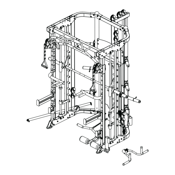
Summary of Contents for body Power BPMFSRD
- Page 1 BPMFSRD Multi-Function Smith Machine with Half Rack and Dual Adjustable Pulley Installation Instructions IMPORTANT: Please read the Safety Guidelines and Installation Instructions in this manual before assembly of this product.
- Page 2 Safety Guidelines When Using This Product Personal Safety during Assembly. Assistance may be required during assembly of this product. • Before beginning assembly, please take the time to read the instructions thoroughly. • Read each step in the assembly instructions and follow the steps in sequence. Do not skip ahead.
- Page 3 • Breath properly. Inhale during the eccentric phase of the exercise, and exhale during the lifting, or concentric phase. Never hold your breath during any part of an exercise. • Always wear the appropriate clothing and shoes when exercising. Wearing comfortable athletic shoes with good support and loose fitting, breathable clothing will reduce the risk of injury.
-
Page 4: Table Of Contents
GUIDE RODS: Wipe clean with a dust free rag. Lubricate with a Silicon or Teflon based lubricant. ADJUSTMENTS / LOCKING PINS / TIGHTENING KNOBS: Check all pieces for signs of visible wear or damage. Check springs in Snap Links and Pop Pins for proper tension and alignment. If the spring sticks or has lost its rigidity, replace it immediately. -
Page 5: Parts List
Spare Parts List Serial No. Description Note Qty. BK-3059G-001 connection tube BK-3059G-002 upright frame left BK-3059G-003 upright frame right BK-3059G-004 bending tube left BK-3059G-005 bending tube right BK-3059G-006 upper connection tube BK-3059G-007 upper bending tube right BK-3059G-008 upper bending tube left BK-3059G-009 hexagon bolt M10*75... - Page 6 Spare Parts List Serial No Description Note Qty. BK-3059G-038 button head socket screw M12*40 BK-3059G-039 spring washer Φ12 BK-3059G-040 washer Φ12 BK-3059G-041 barbell rod BK-3059G-042 inner pipe Φ48*298*2.5 BK-3059G-043 rubber pad Φ60*Φ26*25 BK-3059G-044 upper connection tube short BK-3059G-045 lower connection tube BK-3059G-046 big sliding sleeve BK-3059G-047...
- Page 7 Spare Parts List Serial No. Description Note Qty. BK-3059G-076 hexagon bolt M8*20 BK-3059G-077 washer Φ8 BK-3059G-078 lock nut BK-3059G-079 core trainer BK-3059G-080 powder metallurgy sleeve Φ33.2*Φ29*Φ20*18 BK-3059G-081 barbell rod cup BK-3059G-082 big washer Φ25*Φ10*2.0 BK-3059G-083 dip bar left BK-3059G-084 dip bar right BK-3059G-085 barbell rod holder right BK-3059G-086...
- Page 8 Spare Parts List Serial No. Description Note Qty. BK-3059G-114 solid rod Φ25 BK-3059G-115 spring washer Φ6 BK-3059G-116 50-70 inner plug □50*70*2.0 BK-3059G-117 inner tube n25*2*295 BK-3059G-118 stainless steel tube-310 Φ50*0.8*310 BK-3059G-119 barbell bar plug n51*n42.5*36.6L BK-3059G-120 inner cap n60*n48.5*27L BK-3059G-121 spring washer Φ8 BK-3059G-122...
- Page 9 Spare Parts List Serial No. Description Note Qty. BK-3059G-152 hexagon socket plain head bolt M12*25 BK-3059G-153 stainless steel bushing Φ25*57 BK-3059G-154 tube plug Φ48*2 BK-3059G-155 short safety catch outside rubber-open 85mm BK-3059G-156 short safety catch outside rubber 85mm BK-3059G-157 long safety catch outside rubber 387mm BK-3059G-158 spring collar...
-
Page 10: Assembly Step-1
Assembly Step-1 Drawing 1 Fix bending tube left-4 fastening on upright frame left-2 using M10x75 hexagon bolt-9, Φ10 washer-11 and M10 lock nut-10. 2 Fix bending tube right-5 fastening on upright frame right-3 using M10x75 hexagon bolt-9, Φ 10 washer-11 and M10 lock nut-10. 3 Connect connection tube-1,upright frame left-2 and upright frame right-3 using M10x75 hexagon bolt-9, Φ... - Page 11 Assembly Step - 1 Drawing No. Description Note Qty. 1 connection tube 2 upright frame left 3 upright frame right 4 bending tube left 5 bending tube right 6 upper connection tube 7 upper bending tube right 8 upper bending tube left 9 hexagon bolt M10*75 10 lock nut...
- Page 12 Step - 1 Factory Assembly Drawing No. Description Note Qty. 3 upright frame right 14 oval mat 15 plug Φ76*2 56 nut upright frame right QTY: 1PCS/SET No. Description Note Qty. 2 upright frame left 14 oval mat 15 plug Φ76*2 56 nut upright frame left...
-
Page 13: Assembly Step-2
Assembly Step-2 Drawing 1 Fix sliding tube left-21 on tube with hole left-18. 2 Fix sliding tube right-20 on tube with hole right-17. 3 Fix upright tube-16 and tube with hole left-18 tube with hole right-17 fastening on assembly , step-1 using M10x75 hexagon bolt-9, Φ10 washer-11, M10 lock nut-10, upper plate-13 and lower plate-19. - Page 14 Assembly Step - 2 Drawing No. Description Note Qty. No. Description Note Qty. 9 hexagon bolt M10*75 tube with hole left 10 lock nut lower plate 11 washer Φ10 sliding tube right 12 chin up bar sliding tube left 13 upper plate foot tube cover 16 upright tube end tube...
- Page 15 Assembly Step - 2 Enlarged Drawing...
- Page 16 Step - 2 Factory Assembly Drawing No. Description Note Qty. 18 tube with hole left 60 pipe plug □50*50*t2.0 QTY: 1PCS/SET No. Description Note Qty. 17 tube with hole right 60 pipe plug □50*50*t2.0 tube with hole right QTY: 1PCS/SET No.
- Page 17 Step - 2 Factory Assembly Drawing No. Description Note Qty. 12 chin up bar 61 sleeve Φ25*160 96 cover Φ25 97 bolt M4*5 98 hanging ring 77 washer Φ8 78 lock nut chin up bar 99 socket head pipe plug Φ25*1.5 QTY: 1PCS/SET No.
- Page 18 Step - 2 Factory Assembly Drawing No. Description Note Qty. 20 sliding tube right 100 sleeve □50-□60 101 T shape play pin Φ10 11 washer Φ10 59 hexagon bolt M10*45 10 lock nut 57 pulley Φ95 103 rotation bearing Φ20*M10*67 102 pulley rotation frame sliding tube right 80 powder metallurgy sleeve...
-
Page 19: Assembly Step-3
Assembly Step-3 Drawing 1 Fix lower base-25 fastening on lower plate using M10x90 hexagon bolt-33, Φ10 washer-11 and M10 lock nut-10. 2 Fix upper base-26 fastening on upper plate using M10x90 hexagon bolt-33, Φ10 washer-11 and M10 lock nut-10. 3 Guide rod-27 in turn through lock sleeve-28, sliding sleeve-29, rubber pad-43, safety hook left- 32 and rubber pad with groove-30 fastening on base using M8x10 socket set screw-34 4 Barbell rod-41 in turn through sliding sleeve-29, check ring-36, inner pipe-42, pipe-37 and end cap- 35 fastening using M12x40 button head socket screw-38, Φ12 spring washer-39 and Φ12 washer-... - Page 20 Assembly Step - 3 Drawing 35 40 39 38 No. Description Note Qty. No. Description Note Qty. 10 lock nut headless socket hexagon bolt M8*10 11 washer Φ10 end cap Φ51*Φ42.5*36.6L 25 lower base check ring Φ60*48.5*27L 26 upper base pipe Φ50*310*T0.5 27 guide rod...
- Page 21 Factory Assembly Drawing Step - 3 No. Description Note Qty. 29 sliding sleeve 107 thumbstall Φ21*Φ15*35 108 straight line bearing LM25UU 109 bearing 6005 110 spring collar Φ40 sliding sleeve QTY: 2PCS/SET No. Description Note Qty. 31 safety hook right 108 straight line bearing LM25UU 110 spring collar...
- Page 22 Factory Assembly Drawing Step - 3 No. Description Note Qty. 111 hook-left 41 barbell rod 112 hexagon socket cap screws M6*16 113 hook-right 114 solid rod Φ25 115 spring washer Φ6 barbell rod QTY: 1PCS/SET...
-
Page 23: Assembly Step-4
Assembly Step-4 Drawing 1 Fix upper connection tube short-44 fastening on main frame using M12x30 hexagon bolt-52, Φ12 spring washer-39 and Φ12 washer-40. 2 Fix lower connection tube-45 fastening on main frame using M12x30 hexagon bolt-52, Φ12 spring washer-39 and Φ12 washer-40. 3 Fix double pulley bracket-53 fastening on double pulley bracket-45 using M10x55 hexagon bolt-51, Φ10 washer-11 and M10 lock nut-10. - Page 24 Assembly Step - 4 Drawing No. Description Note Qty. 10 lock nut 11 washer Φ10 39 spring washer Φ12 40 washer Φ12 44 upper connection tube short 45 lower connection tube 46 big sliding sleeve 47 guide rod hollow 48 rubber pad 49 hexagon bolt M10*25 50 hexagon bolt...
- Page 25 Step - 4 Factory Assembly Drawing No. Description Note Qty. 44 upper connection tube short upper connection tube short 116 50-70 inner plug □50*70*2.0 QTY: 1PCS/SET guide rod hollow No. Description Note Qty. QTY: 1PCS/SET 45 lower connection tube 116 50-70 inner plug □50*70*2.0 14 oval mat...
- Page 26 Step - 4 Factory Assembly Drawing No. Description Note Qty. 117 inner tube Φ25*2*295 118 stainless steel tube-310 Φ50*0.8*310 119 barbell bar plug Φ51*Φ42.5*36.6L 120 inner cap Φ60*Φ48.5*27L 40 washer Φ12 39 spring washer Φ12 38 button head socket screw M12*40 122 rubber gasket Φ70*Φ50*10...
-
Page 27: Assembly Step-5
Assembly Step-5 Drawing 1 As the shown in the figure fix pulley-57 fastening on main frame and ”-“ shape pulley frame-63 using M10x45 hexagon bolt-59, Φ10 washer-11 and M10 lock nut- 10. 2 As the shown in the figure put the wire-62. 3 Connect short bar-64 to wire using chain + 2 snap hook-66. - Page 28 Assembly Step - 5 Drawing No. Description Note Qty. 10 lock nut 11 washer Φ10 49 hexagon bolt M10*25 57 pulley Φ95 59 hexagon bolt M10*45 62 wire Φ5*4740mm 63 pulley frame 64 short bar 65 footplate 66 chain + 2 snap hook...
- Page 29 Factory Assembly Drawing Step - 5 No. Description Note Qty. 62 wire Φ5*4740mm 125 wire-ball head wire 126 wire-ball head part QTY: 1 PCS/SET 127 hexagon socket cap screws M5*25 No. Description Note Qty. short bar 64 short bar QTY: 1 PCS/SET 128 handle cover Φ32*180...
-
Page 30: Assembly Step-6
Assembly Step-6 Drawing Internal wire schematic 1 As the shown in the figure fix pulley-57 fastening on upper plate using M10x80 hexagon bolt-24, Φ 10 washer-11 and M10 lock nut-10 and pulley spacer sleeve-68. 2 Fix pulley-57 fastening on ”-“ shape pulley frame-63 using M10x45 hexagon bolt-59, Φ10 washer- 11 and M10 lock nut-10. - Page 31 Assembly Step - 6 Drawing the wire should be keep vertical No. Description Note Qty. 10 lock nut 11 washer Φ10 24 hexagon bolt M10*80 49 hexagon bolt M10*25 57 pulley Φ95 59 hexagon bolt M10*45 63 ”-“ shape pulley frame 67 wire Φ5*4185 68 pulley spacer sleeve...
- Page 32 Factory Assembly Drawing Step - 6 No. Description Note Qty. 67 wire Φ5*4185 wire 125 wire-ball head 126 wire-ball head part QTY: 2 PCS/SET 127 hexagon socket cap screws M5*25...
-
Page 33: Assembly Step-7
Assembly Step-7 Drawing 1 Fix pulley-57 fastening on ”-“ shape pulley frame-63 using M10x45 hexagon bolt-59, Φ10 washer- 11 and M10 lock nut-10. 2 As the shown in the figure connect wire-70, pulley frame-69 and 5 section chain + snap hook-71 on the main frame. - Page 34 Assembly Step - 7 Drawing No. Description Note Qty. 11 washer Φ10 10 lock nut 57 pulley Φ95 59 hexagon bolt M10*45 69 pulley frame 70 wire Φ5*1705mm 71 section chain + snap hook...
-
Page 35: Assembly Step-8
Assembly Step-8 Drawing Internal wire schematic 1 Fix pulley-57 fastening on main frame using M10x45 hexagon bolt-59, Φ10 washer-11 and M10 lock nut-10. 2 Fix pulley-73 fastening on lower plate using M10x80 hexagon bolt-24, Φ10 washer-11 and M10 lock nut-10 and pulley spacer sleeve-68. 3 As the shown in the figure put the wire-72 on the machine. - Page 36 Assembly Step - 8 Drawing No. Description Note Qty. 11 washer Φ10 10 lock nut 24 hexagon bolt M10*80 49 hexagon bolt M10*25 57 pulley Φ95 59 hexagon bolt M10*45 68 pulley spacer sleeve Φ20*10.5*L20.5 72 wire Φ5x9715mm 73 pulley Φ50...
-
Page 37: Assembly Step-9
Assembly Step-9 Drawing 1 Fix shield-74 fastening on main frame using M8x20 hexagon bolt-76, Φ8 washer-77 and M8 lock nut-78. 2 Fix barbell plate holder-75 on main frame using M8x20 hexagon bolt-76, Φ8 washer-77. - Page 38 Assembly Step - 9 Drawing No. Description Note Qty. 74 shield 75 barbell plate holder 76 hexagon bolt M8*20 77 washer Φ8 78 lock nut...
- Page 39 Factory Assembly Drawing Step - 9 No. Description Note Qty. 74 shield shield 129 handlebar grip Φ8*100 QTY: 1 PCS/SET 131 132 No. Description Note Qty. 130 stainless steel tube Φ50*0.8*200 131 barbell bar tube Φ48*1.5*198 132 inner support cap φ70*φ44.8*φ25.5*20 133 outside support cap φ50*φ44.8*φ25.5...
-
Page 40: Assembly Step-10
Assembly Step-10 Drawing 1 Fix core trainer-79 fastening on main frame using M10x25 hexagon bolt-49, Φ10 big washer-82 and powder metallurgy sleeve-80. 2 Fix barbell rod cup-81 fastening on upright frame using M10x95 hexagon bolt-50, Φ10 washer-11 and M10 lock nut-10. - Page 41 Assembly Step - 10 Drawing 50 11 No. Description Note Qty. 11 washer Φ10 10 lock nut 49 hexagon bolt M10*25 50 hexagon bolt M10*95 79 core trainer 80 powder metallurgy sleeve Φ33.2*Φ29*Φ20*18 81 barbell rod cup 82 big washer Φ25*Φ10*2.0...
- Page 42 Step - 10 Factory Assembly Drawing No. Description Note Qty. 79 core trainer 136 rotation welidng 137 powder metallurgy sleeve φ50*φ25*15 138 out hexagon bolt M12*25 40 washer Φ12 139 rotation bearing φ25*M12*77 core trainer QTY: 1 PCS/SET...
-
Page 43: Assembly Step-11
Assembly Step-11 Drawing 1 Connect leg curl tube-95 and barbell rod holder short left-87 using T shape pin-94 2 As shown in the firgure,put the attached part on the machine. - Page 44 Assembly Step - 11 Drawing No. Description Note Qty. 83 dip bar left 84 dip bar right 85 barbell rod holder right 86 barbell rod holder left 87 barbell rod holder short left 88 barbell rod holder short right 95 leg curl tube 90 long bar 91 ship rod 92 hand belt...
- Page 45 Step - 11 Factory Assembly Drawing pull lift device QTY: 1 PCS/SET No. Description Note Qty. 93 pull lift device 140 pull sleeve 141 locking spring knob 142 straight tube φ25*150 143 straight tube-2 φ25*130 96 cover Φ25 97 bolt M4*5 40 washer Φ12...
- Page 46 Factory Assembly Drawing Step - 11 群。 No. Description Note Qty. 95 leg curl tube 145 sponge end cap-inner 146 100 sponge φ100*180 147 sponge end cap-outsidse 148 hexagon socket button head screws M8*25 149 pull pin φ10 135 nut leg curl tube QTY: 1 PCS/SET 动...
- Page 47 Factory Assembly Drawing Step - 11 No. Description Note Qty. 84 dip bar right 151 handle cover φ25*150 152 hexagon socket plain head bolt M12*25 153 stainless steel bushing Φ25*57 99 socket head pipe plug Φ25*1.5 154 tube plug Φ48*2 40 washer Φ12 QTY: 1 PCS/SET...
- Page 48 Step - 11 Factory Assembly Drawing No. Description Note Qty. 87 barbell rod holder short left 153 stainless steel bushing Φ25*57 40 washer Φ12 152 hexagon socket plain head bolt M12*25 155 short safety catch outside rubber-open 85mm barbell rod holder short left QTY: 1 PCS/SET No.
- Page 49 Step - 11 Factory Assembly Drawing No. Description Note Qty. 91 ship rod 158 spring collar Φ28 159 inner pipe 160 inner shaft 161 washer Φ33*Φ12*3 162 bearing 6001-2RS 163 bearing sleeve Φ33*Φ22*35 164 T shape bolt Φ6.3*50.5 165 Tshape bush Φ13*Φ6.4*10.5 166 U shape fastener 167 check ring...
- Page 50 Step - 11 Factory Assembly Drawing No. Description Note Qty. 85 barbell rod holder right 153 stainless steel bushing Φ25*57 152 hexagon socket plain head bolt M12*25 157 long safety catch outside rubber 387mm 40 washer Φ12 barbell rod holder right QTY: 1 PCS/SET No.
Need help?
Do you have a question about the BPMFSRD and is the answer not in the manual?
Questions and answers