
Related Manuals for body Power BK-4006


Summary of Contents for body Power BK-4006
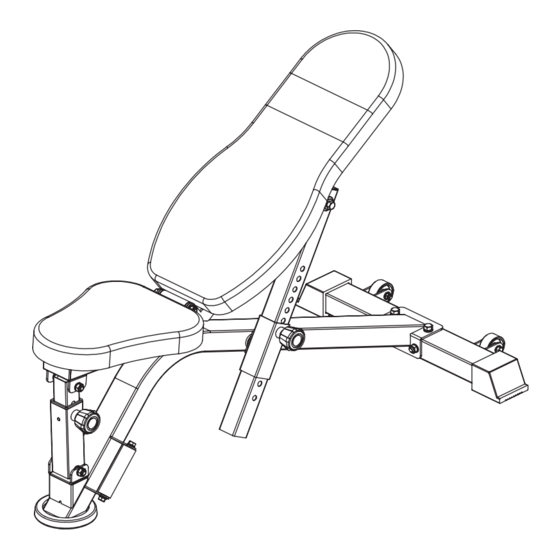
- Page 1 BK-4006(BPBECUB) Compact Utility Bench Installation Instructions IMPORTANT: Please read the Safety Guidelines and Installation Instructions in this manual before assembly of this product.
- Page 2 Safety Guidelines When Using This Product Personal Safety during Assembly. Assistance may be required during assembly of this product. • Before beginning assembly, please take the time to read the instructions thoroughly. • Read each step in the assembly instructions and follow the steps in sequence. Do not skip ahead.
- Page 3 • Breath properly. Inhale during the eccentric phase of the exercise, and exhale during the lifting, or concentric phase. Never hold your breath during any part of an exercise. • Always wear the appropriate clothing and shoes when exercising. Wearing comfortable athletic shoes with good support and loose fitting, breathable clothing will reduce the risk of injury.
- Page 4 GUIDE RODS: Wipe clean with a dust free rag. Lubricate with a Silicon or Teflon based lubricant. ADJUSTMENTS / LOCKING PINS / TIGHTENING KNOBS: Check all pieces for signs of visible wear or damage. Check springs in Snap Links and Pop Pins for proper tension and alignment. If the spring sticks or has lost its rigidity, replace it immediately.
-
Page 5: Table Of Contents
Contents Parts list …………………………………………………………………………………………………………………6 Assembly step-1 …………………………………………………………………………………………………7-9 Assembly step-2 ………………………………………………………………………………………………10-12 Assembly step-3 ………………………………………………………………………………………………13-15 Assembly step-4 ………………………………………………………………………………………………16-18 Assembly step-5 ………………………………………………………………………………………………19-21 Assembly step-6 ………………………………………………………………………………………………22-23 Assembly step-7 ………………………………………………………………………………………………24-25 Bolt length meter... -
Page 6: Parts List
Parts list Serial NO. Description Note Qty. BK-4006-1 base frame BK-4006-2 bending frame BK-4006-3 gasket Φ10 BK-4006-4 lock nut BK-4006-5 hexagon bolt M10*90 BK-4006-6 hexagon bolt M10*25 BK-4006-7 spring gasket Φ10 BK-4006-8 big gasket Φ25*10*2.0 BK-4006-9 back pad outer tube... -
Page 7: Assembly Step-1
Assembly step-1 explosion drawing No. Description Note Qty. base frame bending frame gasket Φ10 lock nut hexagon bolt M10*90 hexagon bolt M10*25 spring gasket Φ10... - Page 8 Factory assembly explosion drawing No. Description Note Qty. gasket Φ8 outer cover □50*70*2.0 roller Φ54*Φ8.5*26 rivet nut hexagon bolt M8*45 lock nut No. Description Note Qty. gasket Φ8 foot cover handle powder metallurgy sleeve Φ32 hexagon bolt M8*20 spring gasket Φ8...
- Page 9 Assembly step-1 drawing Assembly step-1 installation instruction Fix base frame-1 fastening on bending frame-2 using M10*25 hexagon bolt-6, Φ10 spring gasket-7, Φ10 gasket-3, M10x90 hexagon bolt-5 and lock nut-4.
-
Page 10: Assembly Step-2
Assembly step-2 explosion drawing No. Description Note Qty. spring gasket Φ10 big gasket Φ25*10*2.0 back pad outer tube hexagon bolt M10*20... - Page 11 Factory assembly explosion drawing No. Description Note Qty. plum flower pull pin...
- Page 12 Assembly step-2 drawing Assembly step-2 installation instruction Fix back pad outer tube-9 fastening on bending frame-2 using M10*20 hexagon bolt- 10, Φ10 big gasket-8 and Φ10 spring gasket-7.
-
Page 13: Assembly Step-3
Assembly step-3 explosion drawing No. Description Note Qty. seat pad outer tube hexagon bolt M10*85 gasket Φ10 lock nut... - Page 14 Factory assembly explosion drawing No. Description Note Qty. plum flower pull pin tube plug □50-40 powder metallurgy sleeve Φ20*Φ16*Φ...
- Page 15 Assembly step-3 drawing Assembly step-3 installation instruction Fix seat pad outer tube-11 fastening on bending frame-2 using M10*85 hexagon bolt- 12, Φ10 gasket-3 and lock nut-4.
-
Page 16: Assembly Step-4
Assembly step-4 explosion drawing No. Description Note Qty. seat pad adjuster seat pad tube gasket Φ10 lock nut hexagon bolt M10*85... - Page 17 Factory assembly explosion drawing No. Description Note Qty. tube plug □40-80 No. Description Note Qty. powder metallurgy sleeve Φ20*Φ16*Φ...
- Page 18 Assembly step-4 drawing Assembly step-4 installation instruction Fix seat pad adjuster-14 fastening on seat pad tube using M10*85 hexagon bolt-12, Φ 10 gasket-3 and lock nut-4.
-
Page 19: Assembly Step-5
Assembly step-5 explosion drawing No. Description Note Qty. back pad tube spring gasket Φ10 big gasket Φ25*10*2.0 hexagon bolt M10*20 back pad adjuster... - Page 20 Factory assembly explosion drawing No. Description Note Qty. tube plug □40-80 No. Description Note Qty. powder metallurgy sleeve Φ32 tube plug Φ45*45*2.0...
- Page 21 Assembly step-5 drawing Assembly step-5 installation instruction Fix back pad adjuster-21 fastening on back pad tube using M10*20 hexagon bolt-10, Φ10 big gasket-8 and Φ10 spring gasket-7.
-
Page 22: Assembly Step-6
Assembly step-6 explosion drawing No. Description Note Qty. shaft gasket Φ10 lock nut... - Page 23 Assembly step-6 drawing 视图A Assembly step-6 installation instruction As the shown in the figure fix the back pad tube, seat pad tube with the bending frame fasten use shaft-16 and Φ10 gasket-3.
-
Page 24: Assembly Step-7
Assembly step-7 explosion drawing No. Description Note Qty. hexagon bolt M8*55 gasket Φ8 back pad seat pad... - Page 25 Assembly step-7 drawing Assembly step-7 installation instruction Fix seat pad-20 and back pad-19 fastening on the bench using Φ8 gasket-18 and M8*55 hexagon bolt-17.
Need help?
Do you have a question about the BK-4006 and is the answer not in the manual?
Questions and answers