
Related Manuals for body Power BK-3018


Summary of Contents for body Power BK-3018
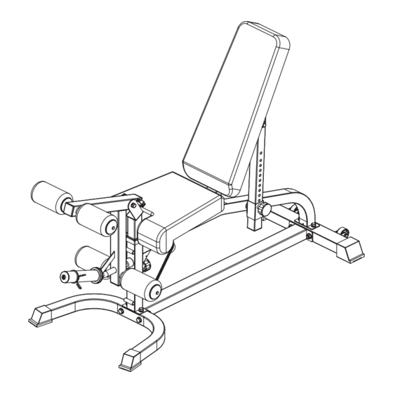
- Page 1 BK-3018(BPBEMFUB) Multi-Function Utility Bench Installation Instructions 综 合 训 练 器 IMPORTANT: Please read the Safety Guidelines and Installation Instructions in this manual before assembly of this product.
- Page 2 Safety Guidelines When Using This Product Personal Safety during Assembly. Assistance may be required during assembly of this product. • Before beginning assembly, please take the time to read the instructions thoroughly. • Read each step in the assembly instructions and follow the steps in sequence. Do not skip ahead.
- Page 3 • Breath properly. Inhale during the eccentric phase of the exercise, and exhale during the lifting, or concentric phase. Never hold your breath during any part of an exercise. • Always wear the appropriate clothing and shoes when exercising. Wearing comfortable athletic shoes with good support and loose fitting, breathable clothing will reduce the risk of injury.
- Page 4 GUIDE RODS: Wipe clean with a dust free rag. Lubricate with a Silicon or Teflon based lubricant. ADJUSTMENTS / LOCKING PINS / TIGHTENING KNOBS: Check all pieces for signs of visible wear or damage. Check springs in Snap Links and Pop Pins for proper tension and alignment. If the spring sticks or has lost its rigidity, replace it immediately.
- Page 5 Contents Parts list Assembly step 1 8-10 Assembly step 2 11-13 Assembly step 3 ..14-16 Assembly step 4 ..17-19 Assembly step 5 ..20-22 Assembly step 6 ..23-25 Assembly step 7 ..26-27...
- Page 6 Parts list Serial NO. Description Note Qty. BK-3018-1 middle base frame BK-3018-2 front bending base frame BK-3018-3 back base frame BK-3018-4 hexagon bolt M12*70 BK-3018-5 gasket Φ12 BK-3018-6 lock nut BK-3018-7 hexagon bolt M12*90 BK-3018-8 bending tube BK-3018-9 gasket M10*20...
- Page 7 Parts list BK-3018-42 hexagon bolt M10*25 BK-3018-43 foot cover □50*50 BK-3018-44 rivet nut BK-3018-45 foot cover □50*70 BK-3018-46 roller Φ54 BK-3018-47 hexagon bolt M8*45 BK-3018-48 lock nut BK-3018-49 powder metallurgy sleeve Φ32*Φ28*Φ20*18 BK-3018-50 tube plug □50*50/□45*45 BK-3018-51 bearing 6001 BK-3018-52 tube plug □40*60*2...
- Page 8 Assembly step-1 explosion drawing No. Description Note Qty. middle base frame front bending base frame back base frame hexagon bolt M12*70 gasket Φ12 lock nut hexagon bolt M12*90...
- Page 9 Factory assembly explosion drawing No. Description Note Qty. foot cover □50*50 rivet nut No. Description Note Qty. gasket Φ8 foot cover □50*70 roller Φ54 hexagon bolt M8*45 lock nut...
- Page 10 Assembly step-1 drawing Assembly step-1 installation instruction 1 Fix middle base frame-1 and front bending base frame-2 using M12*70 hexagon bolt-4, Φ12 gasket-5, M12 lock nut-6. 2 Fix back base frame-3 fastening on middle base frame-1 using M12*90 hexagon bolt-7, Φ12 gasket-5, M12 lock nut-6.
- Page 11 Assembly step-2 explosion drawing No. Description Note Qty. bending tube hexagon bolt M10*25 gasket Φ10 locking spring knob M18*1.5-35 spring gasket Φ10...
- Page 12 Factory assembly explosion drawing No. Description Note Qty. powder metallurgy sleeve Φ32*Φ28*Φ20*18 tube plug □50*50/□45*45...
- Page 13 Assembly step-2 drawing Assembly step-2 installation instruction 1 Fix bending tube-8 fastening on main frame using M10*25 hexagon bolt-42, Φ10 gasket-10, Φ10 spring gasket-12. 2 Put locking spring knob-11 on the bending tube-8.
- Page 14 Assembly step-3 explosion drawing No. Description Note Qty. back pad tube shaft Φ12*128-M10 gasket Φ10 lock nut selector tube big gasket Φ30*Φ10.5*3.0 hexagon bolt M10*20 back pad rotating sleeve locking spring knob M18*1.5-35 spring gasket Φ10...
- Page 15 Factory assembly explosion drawing No. Description Note Qty. bearing 6001 tube plug □40*60*2 No. Description Note Qty. powder metallurgy sleeve Φ32*Φ28*Φ20*18 tube plug □45*45...
- Page 16 Assembly step-3 drawing Assembly step-3 installation instruction 1 Fix selector tube-16, back pad rotating sleeve-18 and locking spring knob-11 on the main frame. 2 Connect back pad tube-13, selector tube-16 and main frame using shaft-14, Φ10 gasket -10 and M10 lock nut-15. 3 Fix selector tube-16 and back pad rotating sleeve-18 using M10*20 hexagon bolt-9, Φ10 big gasket-17 and Φ10 spring gasket-12.
- Page 17 Assembly step-4 explosion drawing No. Description Note Qty. shaft Φ12*128-M10 seat pad frame gasket Φ10 lock nut magnetic pin Φ10*80...
- Page 18 Factory assembly explosion drawing No. Description Note Qty. bearing 6001 tube plug □40*60*2...
- Page 19 Assembly step-4 drawing Assembly step-4 installation instruction 1 Fix seat pad frame-19 on the main frame using shaft-14, Φ10 gasket-10, M10 lock 2 Put magnetic pin-41 on the main frame.
- Page 20 Assembly step-5 explosion drawing No. Description Note Qty. seat pad hexagon bolt M8*55 gasket Φ8 hexagon bolt M8*25 back pad foam rod-450 foam inner cover foam outer cover foam Φ100*175 allen bolt M8*25 leg curl tube magnetic pin Φ10*80...
- Page 21 Factory assembly explosion drawing No. Description Note Qty. handle cover Φ32*Φ25*130 tube plug Φ32*Φ29*Φ26*29 tube plug □50*50/Φ32...
- Page 22 Assembly step-5 drawing Assembly step-5 installation instruction 1 Fix the seat pad-20 and back pad-24 onto the main frame using Φ8 gasket-22, M8*25 hexagon bolt-23. 2 Fix foam tube-28, foam inner cover-29, foam-31 and foam outer cover-30 into the leg curl tube as shown in the figure using M8*25 allen bolt. 3 Put the leg curl tube-40 to the main body and fix them with magnetic pin-41.
- Page 23 Assembly step-6 explosion drawing No. Description Note Qty. leg curl tube shaft Φ20*57-M10 hexagon bolt M10*20 gasket Φ10 T shape pin-85 Φ10*85 foam rod-450 foam inner cover foam outer cover foam Φ100*175 allen bolt M8*25 upright tube spring gasket Φ10 spring collar Φ50...
- Page 24 Factory assembly explosion drawing No. Description Note Qty. tube plug Φ32*Φ29*Φ26*29 tube plug □50*50*2.0 powder metallurgy sleeve Φ32*Φ28*Φ20*18 tube Φ50*0.8 tube Φ48*1.5 tube plug Φ50*Φ44.8*Φ25.5 tube plug Φ70*Φ44.8*Φ25.5*30 rubber cushion Φ40*Φ25*29 allen bolt M8*20...
- Page 25 Assembly step-6 drawing Assembly step-6 installation instruction 1 Fix shaft-26 and upright tube-33 fastening on leg curl tube-25 using Φ10 washer- 10, Φ10 spring washer-12 and M10*20 hexagon bolt-9. 2 Assemble the foam rod-28, foam inner cover-29, foam-31 and foam outer cover-30 to leg curl tube-25 as shown in the figure, and fix it with M8*25 allen bolt-32 at both ends.
- Page 26 Assembly step-7 explosion drawing No. Description Note Qty. chest pad hexagon bolt M8*25 gasket Φ8 barbell support tube connection plate hexagon bolt M10*65 gasket Φ10 lock nut chest pad tube...
- Page 27 Assembly step-7 drawing Assembly step-7 installation instruction 1 As shown in the figure fix barbell support tube-36, connection plate-37 fastening on the chest pad tube-39 using M10*65 hexagon head bolt-38, Φ10 gasket-10 and 2 Fix chest pad-35 onto the chest pad tube-39 and fix it with M8*25 hexagon bolt-23. 3 Assemble the whole set of barbell supporting trusteeship accessories onto the main body with adjustable height.When not needed, the attachment can be removed at any time, and the attachment can be replaced to achieve other training...
Need help?
Do you have a question about the BK-3018 and is the answer not in the manual?
Questions and answers