
Related Manuals for body Power BPMFSRD


Summary of Contents for body Power BPMFSRD
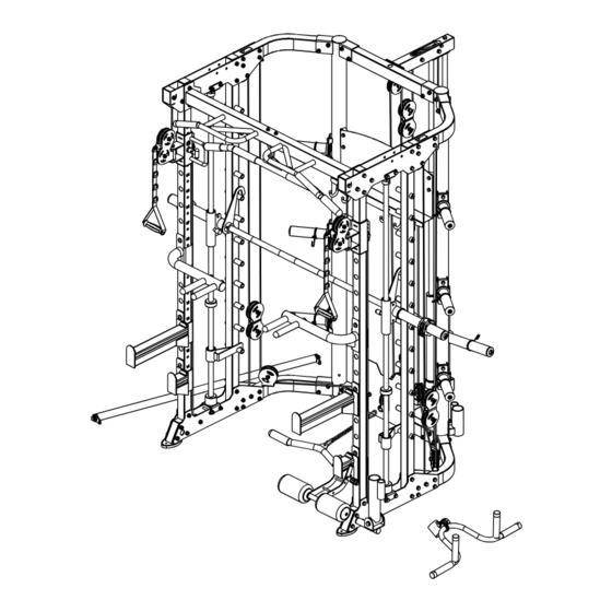
- Page 1 BPMFSRD Multi-Function Smith Machine with Half Rack and Dual Adjustable Pulley Installation Instructions IMPORTANT: Please read the Safety Guidelines and Installa�on Instruc�ons in this manual before assembly of this product.
- Page 2 Safety Guidelines When Using This Product Personal Safety during Assembly. Assistance may be required during assembly of this product. • Before beginning assembly, please take the �me to read the instruc�ons thoroughly. • Read each step in the assembly instruc�ons and follow the steps in sequence. Do not skip ahead.
-
Page 3: Product Maintenance
• Breath properly. Inhale during the eccentric phase of the exercise, and exhale during the li�ing, or concentric phase. Never hold your breath during any part of an exercise. • Always wear the appropriate clothing and shoes when exercising. Wearing comfortable athle�c shoes with good support and loose fi�ng, breathable clothing will reduce the risk of injury. - Page 4 GUIDE RODS: GUIDE RODS: Wipe clean with a dust free rag. Lubricate with a Silicon or Teflon based lubricant. Wipe clean with a dust free rag. Lubricate with a Silicon or Teflon based lubricant. ADJUSTMENTS / LOCKING PINS / TIGHTENING KNOBS: ADJUSTMENTS / LOCKING PINS / TIGHTENING KNOBS: Check all pieces for signs of visible wear or damage.
-
Page 5: Spare Parts List
Spare Parts List Serial No Descrip�on Note BK-3059-001 connec�on tube BK-3059-002 upright frame le� BK-3059-003 upright frame right BK-3059-004 bending tube le� BK-3059-005 bending tube right BK-3059-006 upper connec�on tube BK-3059-007 upper bending tube right BK-3059-008 upper bending tube le� BK-3059-009 hexagon bolt M10*75... - Page 6 Spare Parts List Serial No Descrip�on Note BK-3059-038 bu�on head socket screw M12*40 BK-3059-039 spring washer Φ12 BK-3059-040 washer Φ12 BK-3059-041 barbell rod BK-3059-042 inner pipe Φ48*298*2.5 BK-3059-043 rubber pad Φ60*Φ26*25 BK-3059-044 upper connec�on tube short BK-3059-045 lower connec�on tube BK-3059-046 hang frame BK-3059-047...
- Page 7 Spare Parts List Serial No Descrip�on Note BK-3059-076 hexagon bolt M8*20 BK-3059-077 washer Φ8 BK-3059-078 lock nut BK-3059-079 core trainer BK-3059-080 powder metallurgy sleeve Φ33.2*Φ29*Φ20*18 BK-3059-081 barbell rod cup BK-3059-082 big washer Φ25*Φ10*2.0 BK-3059-083 dip bar le� BK-3059-084 dip bar right BK-3059-085 barbell rod holder right BK-3059-086...
- Page 8 Spare Parts List Serial No Descrip�on Note BK-3059-114 solid rod Φ25 BK-3059-115 spring washer Φ6 BK-3059-116 50-70 inner plug □50*70*2.0 BK-3059-117 inner tube Φ25*2*295 BK-3059-118 stainless steel tube-310 Φ50*0.8*310 BK-3059-119 barbell bar plug Φ51*Φ42.5*36.6L BK-3059-120 inner cap Φ60*Φ48.5*27L BK-3059-121 spring washer Φ8 BK-3059-122 rubber gasket...
- Page 9 Spare Parts List Serial No Descrip�on Note handle cover φ25*150 BK-3059-151 hexagon socket plain head bolt M12*25 BK-3059-152 stainless steel bushing Φ25*57 BK-3059-153 tube plug Φ48*2 BK-3059-154 short safety catch outside rubber-open 85mm BK-3059-155 short safety catch outside rubber 85mm BK-3059-156 long safety catch outside rubber 387mm...
- Page 10 Assembly Step-1 Drawing 1 Fix bending tube le�-4 fastening on upright frame le�-2 using M10x75 hexagon bolt-9, Φ10 washer-11 and M10 lock nut-10. 2 Fix bending tube right-5 fastening on upright frame right-3 using M10x75 hexagon bolt-9, Φ 10 washer-11 and M10 lock nut-10. 3 Connect connec�on tube-1,upright frame le�-2 and upright frame right-3 using M10x75 hexagon bolt-9, Φ...
- Page 11 Assembly Step 1-A No. Descrip�on Note Qty. 1 connec�on tube 2 upright frame le� 3 upright frame right 4 bending tube le� 5 bending tube right 6 upper connec�on tube 7 upper bending tube right 8 upper bending tube le� 9 hexagon bolt M10*75 10 lock nut...
- Page 12 Assembly Step 1-B No. Descrip�on Note Qty. 3 upright frame right 14 oval mat 15 plug Φ76*1.5 56 nut upright frame right QTY: 1PCS/SET No. Descrip�on Note Qty. 2 upright frame le� 14 oval mat 15 plug Φ76*1.5 56 nut Assembly Step 1 -B upright frame left QTY: 1PCS/SET...
- Page 13 Assembly Step-2 Drawing 1 Fix sliding tube le�-21 on tube with hole le�-18. 2 Fix sliding tube right-20 on tube with hole right-17. 3 Fix upright tube-16 and tube with hole le�-18 tube with hole right-17 fastening on assembly , step-1 using M10x75 hexagon bolt-9, Φ10 washer-11, M10 lock nut-10, upper plate-13 and lower plate-19.
- Page 14 Assembly Step 2-A No. Descrip�on Note Qty. No. Descrip�on Note Qty. 9 hexagon bolt M10*75 tube with hole le� 10 lock nut lower plate 11 washer Φ10 sliding tube right 12 chin up bar sliding tube le� 13 upper plate foot tube cover 16 upright tube end tube...
- Page 15 Assembly Step - 2 Enlarged Drawing...
- Page 16 Assembly Step 2-B No. Descrip�on Note Qty. 18 tube with hole le� 60 pipe plug □50*50*t2.0 tube with hole left QTY: 1PCS/SET Assembly Step 2 -C No. Descrip�on Note Qty. 17 tube with hole right 60 pipe plug □50*50*t2.0 tube with hole right QTY: 1PCS/SET No.
- Page 17 Assembly Step 2-D No. Descrip�on Note Qty. 12 chin up bar 61 sleeve Φ25*160 96 cover Φ25 97 bolt M4*5 98 hanging ring 77 washer Φ8 78 lock nut chin up bar 99 socket head pipe plug Φ25*1.5 QTY: 1PCS/SET Assembly Step 2 -E No.
- Page 18 Assembly Step 2-F No. Descrip�on Note Qty. 20 sliding tube right 100 sleeve □50-□60 101 T shape play pin Φ10 11 washer Φ10 59 hexagon bolt M10*45 Assembly Step 2-F 10 lock nut 57 pulley Φ95 103 rota�on bearing Φ20*M10*67 102 pulley rota�on frame sliding tube right 80 powder metallurgy sleeve...
- Page 19 Assembly Step-3 Drawing 1 Fix lower base-25 fastening on lower plate using M10x90 hexagon bolt-33, Φ10 washer-11 and M10 lock nut-10. 2 Fix upper base-26 fastening on upper plate using M10x90 hexagon bolt-33, Φ10 washer-11 and M10 lock nut-10. 3 Guide rod-27 in turn through lock sleeve-28, sliding sleeve-29, rubber pad-43, safety hook le�- 32 and rubber pad with groove-30 fastening on base using M8x10 socket set screw-34 4 Barbell rod-41 in turn through sliding sleeve-29, check ring-36, inner pipe-42, pipe-37 and end cap- 35 fastening using M12x40 bu�on head socket screw-38, Φ12 spring washer-39 and Φ12 washer-...
- Page 20 Assembly Step 3-A 35 40 39 38 No. Descrip�on Note Qty. No. Descrip�on Note Qty. 10 lock nut headless socket hexagon bolt M8*10 11 washer Φ10 end cap Φ51*Φ42.5*36.6L 25 lower base check ring Φ60*48.5*27L 26 upper base pipe Φ50*310*T0.5 27 guide rod Φ25*1850 bu�on head socket screw...
- Page 21 Assembly Step 3-B Descrip�on Note sliding sleeve thumbstall Φ21*Φ15*35 straight line bearing LM25UU bearing 6005 spring collar Φ40 sliding sleeve QTY: 2PCS/SET Assembly Step 3-C No. Descrip�on Note Qty. 31 safety hook right 108 straight line bearing LM25UU 110 spring collar Φ40 safety hook right QTY: 1PCS/SET...
- Page 22 Assembly Step 3-E No. Descrip�on Note Qty. 111 hook-le� 41 barbell rod 112 hexagon socket cap screws M6*16 113 hook-right 114 solid rod Φ25 115 spring washer Φ6 barbell rod QTY: 1PCS/SET...
- Page 23 Assembly Step - 4 Drawing 1 Fix upper connec�on tube short-44 fastening on main frame using M12x30 hexagon bolt-52, Φ12 spring washer-39 and Φ12 washer-40. 2 Fix lower connec�on tube-45 fastening on main frame using M12x30 hexagon bolt-52, Φ12 spring washer-39 and Φ12 washer-40.
- Page 24 Assembly Step 4- A Descrip�on Note lock nut washer Φ10 spring washer Φ12 washer Φ12 upper connec�on tube short lower connec�on tube big sliding sleeve guide rod hollow rubber pad hexagon bolt M10*25 hexagon bolt M10*95 hexagon bolt M10*55 hexagon bolt M12*30 double pulley bracket hexagon socket bu�on head screws...
- Page 25 Assembly Step 4 - B No. Descrip�on Note Qty. 44 upper connec�on tube short upper connection tube short 116 50-70 inner plug □50*70*2.0 QTY: 1PCS/SET Assembly Step 4-C guide rod hollow No. Descrip�on Note Qty. QTY: 1PCS/SET 45 lower connec�on tube 116 50-70 inner plug □50*70*2.0 14 oval mat...
- Page 26 Assembly Step 4-D No. Descrip�on Note Qty. 117 inner tube Φ25*2*295 118 stainless steel tube-310 Φ50*0.8*310 119 barbell bar plug Φ51*Φ42.5*36.6L 120 inner cap Φ60*Φ48.5*27L 40 washer Φ12 39 spring washer Φ12 38 bu�on head socket screw M12*40 122 rubber gasket Φ70*Φ50*10 back barbell plate 123 bu�erfly clip...
- Page 27 Assembly Step-5 Drawing 1 As the shown in the figure fix pulley-57 fastening on main frame and ”-“ shape pulley frame-63 using M10x45 hexagon bolt-59, Φ10 washer-11 and M10 lock nut- 10. 2 Assembly pulley-57,Φ50 pulley-73 on main machine using M10*70 hexagon bolt-170, Φ20*10.5*L15 Φ10 powder metallurgy sleeve-168 washer-11,M10 lock nut-10.
- Page 28 Assembly Step 5-A Descrip�on Note lock nut Φ10 washer hexagon bolt M10*25 pulley Φ95 hexagon bolt M10*45 wire Φ5x4130mm ”-“ shape pulley frame short bar footplate chain + 2 snap hook pulley Φ50*310*T0.5 powder metallurgy sleeve Φ20*10.5*L15 hexagon bolt M10*70 lock nut washer Φ8...
- Page 29 Assembly Step 5-B No. Descrip�on Note Qty. 62 wire Φ5*4130mm 125 wire-ball head wire 126 wire-ball head part QTY: 1 PCS/SET 127 hexagon socket cap screws M5*25 Assembly Step 5-C No. Descrip�on Note Qty. short bar 64 short bar QTY: 1 PCS/SET 128 handle cover Φ32*180...
- Page 30 Assembly Step-6 Drawing Internal wire schematic 1 As the shown in the figure fix pulley-57 fastening on upper plate using M10x80 hexagon bolt-24, Φ 10 washer-11 and M10 lock nut-10 and pulley spacer sleeve-68. 2 Fix pulley-57 fastening on ”-“ shape pulley frame-63 using M10x45 hexagon bolt-59, Φ10 washer- 11 and M10 lock nut-10.
- Page 31 Assembly Step 6-A the wire should be keep vertical No. Descrip�on Note Qty. 10 lock nut 11 washer Φ10 24 hexagon bolt M10*80 49 hexagon bolt M10*25 57 pulley Φ95 59 hexagon bolt M10*45 63 ”-“ shape pulley frame 67 wire Φ5*4185 68 pulley spacer sleeve Φ20*10.5*L20.5...
- Page 32 Assembly Step 6-B No. Descrip�on Note Qty. 67 wire Φ5*4185 wire 125 wire-ball head 126 wire-ball head part QTY: 2 PCS/SET 127 hexagon socket cap screws M5*25...
- Page 33 Assembly Step-7 Drawing 1 Fix pulley-57 fastening on ”-“ shape pulley frame-63 using M10x45 hexagon bolt-59, Φ10 washer- 11 and M10 lock nut-10. 2 As the shown in the figure connect wire-70, pulley frame-69 and 5 sec�on chain + snap hook-71 on the main frame.
- Page 34 Assembly Step 7-A Descrip�on Note lock nut Φ10 washer pulley Φ95 hexagon bolt M10*45 pulley frame wire Φ5*1705mm chain + 2 snap hook...
- Page 35 Assembly Step-8 Drawing Assembly Step-8 Drawing Internal wire schematic Internal wire schematic 安 装 步 骤 (八) 安 装 说 明 1 Fix pulley-57 fastening on main frame using M10x45 hexagon bolt-59, Φ10 washer-11 and M10 1 Fix pulley-57 fastening on main frame using M10x45 hexagon bolt-59, Φ10 washer-11 and M10 lock nut-10.
- Page 36 Assembly Step 8-A No. Descrip�on Note Qty. 11 washer Φ10 10 lock nut 24 hexagon bolt M10*80 49 hexagon bolt M10*25 57 pulley Φ95 59 hexagon bolt M10*45 68 pulley spacer sleeve Φ20*10.5*L20.5 72 wire Φ5x9715mm 73 pulley Φ50...
- Page 37 Assembly Step-9 Drawing 1 Fix shield-74 fastening on main frame using M8x20 hexagon bolt-76, Φ8 washer-77 and M8 lock nut-78. 2 Fix barbell plate holder-75 on main frame using M8x20 hexagon bolt-76, Φ8 washer-77.
- Page 38 Assembly Step 9-A No. Descrip�on Note Qty. 74 shield 75 barbell plate holder 76 hexagon bolt M8*20 77 washer Φ8 78 lock nut...
- Page 39 Assembly Step 9-B No. Descrip�on Note Qty. 74 shield shield 129 handlebar grip Φ8*100 QTY: 1 PCS/SET Assembly Step 9-C 131 132 No. Descrip�on Note Qty. 130 stainless steel tube Φ50*0.8*200 131 barbell bar tube Φ48*1.5*198 132 inner support cap φ70*φ44.8*φ25.5*30 133 outside support cap φ50*φ44.8*φ25.5...
- Page 40 Assembly Step-10 Drawing 1 Fix core trainer-79 fastening on main frame using M10x25 hexagon bolt-49, Φ10 big washer-82 and powder metallurgy sleeve-80. 2 Fix barbell rod cup-81 fastening on upright frame using M10x95 hexagon bolt-50, Φ10 washer-11 and M10 lock nut-10.
- Page 41 Assembly Step 10-A No. Descrip�on Note Qty. 11 washer Φ10 10 lock nut 49 hexagon bolt M10*25 50 hexagon bolt M10*95 79 core trainer 80 powder metallurgy sleeve Φ33.2*Φ29*Φ20*18 81 barbell rod cup 82 big washer Φ25*Φ10*2.0...
- Page 42 Assembly Step 10-B No. Descrip�on Note Qty. 79 core trainer 136 rota�on welidng 137 powder metallurgy sleeve φ50*φ25*15 138 out hexagon bolt M12*25 40 washer Φ12 139 rota�on bearing φ25*M12*77 core trainer QTY: 1 PCS/SET...
- Page 43 Assembly Step-11 Drawing 1 Connect leg curl tube-95 and barbell rod holder short le�-87 using T shape pin-94 2 As shown in the firgure,put the a�ached part on the machine.
- Page 44 Assembly Step 11-A No. Descrip�on Note Qty. 83 dip bar le� 84 dip bar right 85 barbell rod holder right 86 barbell rod holder le� 87 barbell rod holder short le� 88 barbell rod holder short right 95 leg curl tube 90 long bar 91 ship rod 92 hand belt...
- Page 45 Assembly Step 11-B pull lift device QTY: 1 PCS/SET No. Descrip�on Note Qty. 93 pull li� device 140 pull sleeve 141 locking spring knob 142 straight tube φ25*150 143 straight tube-2 φ25*130 96 cover Φ25 97 bolt M4*5 40 washer Φ12 144 lock nut 52 hexagon bolt...
- Page 46 Assembly Step 11-C No. Descrip�on Note Qty. 95 leg curl tube 145 sponge end cap-inner 146 100 sponge φ100*180 147 sponge end cap-outsidse 148 hexagon socket bu�on head screws M8*25 149 pull pin φ10 135 nut leg curl tube QTY: 1 PCS/SET Assembly Step 11-D No.
- Page 47 Assembly Step 11-E No. Descrip�on Note Qty. 84 dip bar right 151 handle cover φ25*150 152 hexagon socket plain head bolt M12*25 153 stainless steel bushing Φ25*57 99 socket head pipe plug Φ25*1.5 154 tube plug Φ48*2 40 washer Φ12 QTY: 1 PCS/SET dip bar right Assembly Step 11-F...
- Page 48 Assembly Step 11-G No. Descrip�on Note Qty. 87 barbell rod holder short le� 153 stainless steel bushing Φ25*57 40 washer Φ12 152 hexagon socket plain head bolt M12*25 155 short safety catch outside rubber-open 85mm barbell rod holder short left QTY: 1 PCS/SET Assembly Step 11-H No.
- Page 49 Assembly Step 11-I No. Descrip�on Note Qty. 91 ship rod 158 spring collar Φ28 159 inner pipe 160 inner sha� 161 washer Φ33*Φ12*3 162 bearing 6001-2RS 163 bearing sleeve Φ33*Φ22*35 164 T shape bolt Φ6.3*50.5 165 Tshape bush Φ13*Φ6.4*10.5 166 U shape fastener 167 check ring Φ5 54 hexagon socket bu�on head screws...
- Page 50 Assembly Step 11-G No. Descrip�on Note Qty. 85 barbell rod holder right 153 stainless steel bushing Φ25*57 152 hexagon socket plain head bolt M12*25 157 long safety catch outside rubber 387mm 40 washer Φ12 barbell rod holder right QTY: 1 PCS/SET Assembly Step 11-K No.
Need help?
Do you have a question about the BPMFSRD and is the answer not in the manual?
Questions and answers