Shure AXT900 - Rack Mount Charging Station Manual
- User manual (15 pages) ,
- Quick start manual (8 pages)
Advertisement
General Description
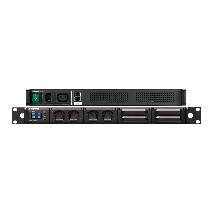
The AXT900 charges up to 8 Shure rechargeable batteries in a single, compact rackmount housing. Interchangeable charging modules accommodate any combination of handheld and bodypack transmitter batteries. The front panel display provides easy metering of all battery parameters, including charge status, time to full, battery health, and battery temperature. When connected to a network, parameters can be monitored remotely using Wireless Workbench.
Features
- Touring-ready battery charging and storage solution with comprehensive status display
- Configurable bays for mixing and matching 8 bodypack and handheld transmitter batteries
- Fully networkable for monitoring of all charging status parameters in Wireless Workbench 6
- Storage mode for charging or discharging batteries to optimal storage voltage
- Tracks battery health using charging cycle count and percentage of original capacity as metrics
- Charges batteries to 50% capacity within 1 hour
- Charges batteries to full capacity in 3 hours
- Simple 3-button interface control
Mounting Instructions
This component is designed to fit into an audio rack.

To prevent injury this apparatus must be securely attached to the rack.

Batteries
This charger is only for use with Shure lithium-ion rechargeable batteries, such as the AXT910, AXT920, or AXT920SL.

Charging Modules
Handheld and bodypack charger modules may be installed interchangeably into the charger.


Remove AC power and batteries when installing charger modules.

- To remove a module, remove the four (4) mounting screws and pull.
- To install, slide the module into the housing (noting the orientation of the guide rails) until it is flush with the housing.
- Replace the screws.
Charge Status LED
Each charger bay has an LED to indicate the status of the battery.
| Red | battery charging |
| Green | charging complete |
| Off | battery inserted incorrectly or battery depleted below 3.0 volts. |
| Amber | charging stopped at reduced capacity (not less than 75% capacity) because the battery is too warm. To reach 100% capacity, a battery must be cooled to below 45°C. |
Inserting Batteries into the Charging Bay
Slide the battery into the charging bay until it locks into place. The charge LED illuminates and the charge cycle begins.

Recovering a Battery from Deep Discharge
A deeply discharged battery is one that has been discharged to less than 3.0 volts. When the charger detects a deeply discharged battery, it automatically enters recovery mode, which charges the battery using a reduced current. The Recovery icon is displayed next to the bay number on the home screen. If recovery is successful, the charger exits recovery mode and charges the battery to capacity. If the battery cannot be recovered in less than 30 minutes, an error message is displayed and charging stops.
Storage Mode
When set to storage mode (Storage Mode = Store at 3.8 V), all batteries are charged or discharged to 3.8 volts, which is ideal for long-term storage.
The charge status LEDs indicate the voltage state:
- Red flashing = battery charging or discharging to 3.8 volts.
- Amber flashing = battery voltage at 3.8 volts.
The following indicators appear on the home screen next to each bay number:
| Rdy | battery at 3.8 V, ready for storage |
| Cold | battery cold |
| Wrm | battery warm |
| Hot | battery hot |
| Err | Error, press SET key for info |
| % | percentage of charge |
Charging or discharging may take several hours. The remaining time is displayed as Time to 3.8 V in the battery monitoring menu (instead of Time to Full).
To exit storage mode:
- Enter the utility menu by holding both arrow keys.
- Navigate to the Storage Mode menu and press the SET key.
- Use the arrow keys to select Off.
- Press the SET key to exit.
When batteries are ready for storage, they should be removed from the charger and placed into a temperature controlled area. Recommended battery storage temperature is 0°C (10°F) to 25°C (77°F).
Controls And Connectors

- LCD screen
Displays battery status and menu settings - Control keys
For navigating the LCD screen. Press and hold both arrow keys to enter or exit the utility menu. - Charging module
Interchangeable modules for handheld and bodypack batteries. - Charge Status LED
Indicates battery charge status - Monitoring Selection LED
This white LED shows which battery is selected in the monitoring menu. - AC power in
Connect to AC mains with supplied power cable. - AC power cascade
Powers additional units. - Ethernet ports (2)
Connect to an Ethernet network to enable remote control and monitoring. - Network status LED (green)
Off = No network link
On = Network link active
Flashing = Network link active, flash rate corresponds to traffic volume. - Network speed LED (amber)
Off = 10 Mbps
On = 100 Mbps - Cooling fan vent
Clean fan screen as needed to maintain airflow. - Power switch
Powers the unit on and off.
Controls

- Use the arrow keys to scroll to the desired menu.
- Press the SET key to enter the selected menu item.
- Use the arrow keys to change a menu parameter.
- Press SET to save the setting.
Press and hold both arrow keys to enter or exit the Utility menu.
Tip: Press and hold the SET button for 1 second to activate the Hardware Identify feature in Wireless Workbench.
Home Screen
When powered on, the charger displays the home screen. Icons indicate the charge level of each battery, and the display alternates to show approximate hours and minutes remaining until the battery is fully charged.
The numbers on the screen correspond to the charging bays 1 through 8 from left to right.

The following messages may be display next to the bay number to indicate battery status:
| CALC | calculating time to full |
| COLD | battery cold |
| WARM | battery warm |
| HOT | battery hot |
| Recovery | recovery mode active |
| Error | error - press SET key for info |
Time to Full
Displays the time remaining until the battery is fully charged.

Battery might not be charged to full capacity if any of the following status indicators appear:
Cold
Charging stopped because battery temperature is too cold. Charging will resume when battery temperature increases.
Warm
Battery charging to less than full capacity (not less than 75%) because of elevated temperature. The amber LED will illuminate when charging has stopped.
Hot
Charging stopped because battery temperature is too hot.
Battery Health
This displays the health of a selected battery as a percentage of the charge capacity of a new battery. Charge capacity (battery life when fully charged) will decline as a result of repeated charge cycles, age, or storage conditions.
Cycle Count
Displays the total number of times that the battery has undergone one full count of discharge and charge. Recharging after discharging half way counts as one half of a cycle. Recharging after discharging a quarter of the way counts as one quarter of a cycle.
Charge Status
Displays charge as a percentage of the total battery capacity. Also displays charge in milliampere-hours (mAh).
Batt. Temp. (Battery Temperature)
Displays both the battery temperature (in Celsius and Fahrenheit) and the status, as follows:
[Normal]
Battery temperature = 0°C to 45°C (32°F to 113°F).
[Cold]
Battery temperature = 0°C (32°F) or lower.
[Warm]
Battery temperature = 45°C to 60°C (113°F to 140°F).
[Hot]
Battery temperature = 60°C (140°F) or higher.
Note: If warm or hot, try setting the fan to Always On or increasing ventilation to the rack.
Network Status
Active
Indicates connectivity with other devices on the network.
Inactive
No connectivity with other devices on the network.
Note: IP address must be valid to enable networked control.
Utility Menu
Press and hold both arrow keys to enter and exit the utility menu, which is used to access network and display settings.

hold both arrow keys
Device ID
This eight-character name is displayed when this device is detected on other network devices or in WWB software.
- Press SET key to enable editing.
- Use the arrow keys to change the characters.
- To finish editing, press the SET key until none of the characters are highlighted.
IP Address Mode: Automatic
This is the default setting for use with a DHCP server, which automatically assigns an IP address.
- Navigate to the IP Mode menu and press the SET key.
- Use the arrow keys to highlight Automatic.
- Press the SET key.
- Use the arrow keys to move the ► to select OK to save or Cancel to discard, and then press the SET key.
IP Address Mode: Manual
Use manual IP addressing to set the IP address and subnet mask when a DHCP server is not available.
- Navigate to the IP mode menu and press the SET key.
- Use the arrow keys to highlight Manual.
- Press the SET key to enable editing of the IP address and the subnet mask.
- Use the arrow keys to move the ► to select IP: or Sub:
- Use the arrow keys and the SET key to edit the IP address and subnet mask.
- Use the arrow keys to move the ► to select OK to save or Cancel to discard, and then press the SET key.
MAC (MAC Address)
Displays the MAC address, which is an embedded, uneditable identification number unique to each device. Used by the network and WWB software to identify components.
Display Invert
This changes the LCD menu from white text on dark background to dark text on a light background.
Firmware
Displays the version of firmware installed on this device.
Fan (Cooling Fan Mode)
Automatic
The fan is enabled and adjusts speed based on the internal temperature of the unit.
Always on
The fan runs continuously at maximum speed to provide maximum cooling in warm environments.
Serial Number
Displays the serial number.
Brightness
Sets the brightness of the LCD to low, medium, or high.
Storage Mode
OFF
Normal charge.
Store at 3.8 V
Charges or discharges all batteries to bring them to a 3.8 volts, ideal for long term storage.
Troubleshooting
| Charge status LED does not illuminate. | Battery is inserted incorrectly or battery cannot accept a charge. Check battery temperature. |
| Battery does not charge | Battery discharged below 3.0 volts. Try another battery. |
Service Fans Maintenance Message
The charger displays the Service Fans message when the fans are unable to cool efficiently.

- Press any key to suppress the message for 20 seconds.
- Service the fans or increase ventilation to the unit to clear the message.
Firmware Updates
Firmware is embedded software in each component that controls functionality. Periodically, new versions of firmware are developed to incorporate additional features and enhancements. To take advantage of design improvements, new versions of the firmware can be uploaded and installed using the Firmware Update Manager tool available in WWB6 software. Firmware is available for download from.
Specifications
Battery Type
Up to 8 rechargeable Li-Ion batteries (AXT910/920/920SL)
Charge Time
50%=1 hour; 100%=3 hours
Charging Module Type
Up to 4 charging modules (AXT901 or AXT902) in any combination
Operating Temperature Range
-18°C (0°F) to 63°C (145°F)
Battery Charging Temperature Range
0°C (32°F) to 60°C (140°F)
Storage Temperature Range
-29°C (-20°F) to 74°C (165°F)
Dimensions
44 mm x 483 mm x 366 mm (1.7 in. x 19.0 in. x 14.4 in.), H x W x D
Weight
4.4 kg (9.8 lbs), without batteries or charging modules
Housing
Steel; Extruded aluminum
Power Requirements
100 to 240 V AC, 50-60 Hz
Current Drain
2.5 A RMS (referenced at 120 V AC)
Networking
Network Interface
Dual Port Ethernet 10/100 Mbps
Network Addressing Capability
DHCP or Manual IP address
Accessories
Optional Accessories
2-bay charging module for bodypack battery AXT901
AXT902 2-bay charging module for handheld battery AXT902
Furnished Accessories
| IEC AC Power Cable (1) | 95A9128 |
| IEC AC Extension Cable (1) | 95A9129 |
| Shielded 3-foot Ethernet Cable (1) | C803 |
| Shielded 8-inch Ethernet Jumper Cable (1) | C8006 |
| Hardware Kit (1) | 90XN1371 |
| Mounting Screws for Charger Modules (8) | 30B13476 |
IMPORTANT SAFETY INSTRUCTIONS
- READ these instructions.
- KEEP these instructions.
- HEED all warnings.
- FOLLOW all instructions.
- DO NOT use this apparatus near water.
- CLEAN ONLY with dry cloth.
- DO NOT block any ventilation openings. Allow sufficient distances for adequate ventilation and install in accordance with the manufacturer's instructions.
- DO NOT install near any heat sources such as open flames, radiators, heat registers, stoves, or other apparatus (including amplifiers) that produce heat. Do not place any open flame sources on the product.
- DO NOT defeat the safety purpose of the polarized or grounding type plug. A polarized plug has two blades with one wider than the other. A grounding type plug has two blades and a third grounding prong. The wider blade or the third prong are provided for your safety. If the provided plug does not fit into your outlet, consult an electrician for replacement of the obsolete outlet.
- PROTECT the power cord from being walked on or pinched, particularly at plugs, convenience receptacles, and the point where they exit from the apparatus.
- ONLY USE attachments/accessories specified by the manufacturer.
- USE only with a cart, stand, tripod, bracket, or table specified by the manufacturer, or sold with the apparatus. When a cart is used, use caution when moving the cart/apparatus combination to avoid injury from tip-over.
![]()
- UNPLUG this apparatus during lightning storms or when unused for long periods of time.
- REFER all servicing to qualified service personnel. Servicing is required when the apparatus has been damaged in any way, such as power supply cord or plug is damaged, liquid has been spilled or objects have fallen into the apparatus, the apparatus has been exposed to rain or moisture, does not operate normally, or has been dropped.
- DO NOT expose the apparatus to dripping and splashing. DO NOT put objects filled with liquids, such as vases, on the apparatus.
- The MAINS plug or an appliance coupler shall remain readily operable.
- The airborne noise of the Apparatus does not exceed 70dB (A).
- Apparatus with CLASS I construction shall be connected to a MAINS socket outlet with a protective earthing connection.
- To reduce the risk of fire or electric shock, do not expose this apparatus to rain or moisture.
- Do not attempt to modify this product. Doing so could result in personal injury and/or product failure.
- Operate this product within its specified operating temperature range.

 This symbol indicates that dangerous voltage constituting a risk of electric shock is present within this unit.
 This symbol indicates that there are important operating and maintenance instructions in the literature accompanying this unit.

Voltages in this equipment are hazardous to life. No user-serviceable parts inside. Refer all servicing to qualified service personnel. The safety certifications do not apply when the operating voltage is changed from the factory setting.
Danger of explosion if incorrect battery replaced. Operate only with AA batteries.
- Battery packs may explode or release toxic materials. Risk of fire or burns. Do not open, crush, modify, disassemble, heat above 140°F (60°C), or incinerate.
- Follow instructions from manufacturer
- Only use Shure charger to recharge Shure rechargeable batteries
![]()
Danger of explosion if battery incorrectly replaced. Replace only with same or equivalent type.- Never put batteries in mouth. If swallowed, contact your physician or local poison control center
- Do not short circuit; may cause burns or catch fire
- Do not charge or use battery packs other than Shure rechargeable batteries
- Dispose of battery packs properly. Check with local vendor for proper disposal of used battery packs.
- Batteries (battery pack or batteries installed) shall not be exposed to excessive heat such as sunshine, fire or the like
Note:
- This equipment is intended to be used in professional audio applications.
- EMC conformance is based on the use of supplied and recommended cable types. The use of other cable types may degrade EMC performance.
- Use this battery charger only with the Shure charging modules and battery packs for which it is designed. Use with other than the specified modules and battery packs may increase the risk of fire or explosion.
- Changes or modifications not expressly approved by Shure Incorporated could void your authority to operate this equipment.
Please follow your regional recycling scheme for batteries, packaging, and electronic waste.
Authorized European representative:
Shure Europe GmbH
Headquarters Europe, Middle East & Africa
Department: EMEA Approval
Jakob-Dieffenbacher-Str. 12
75031 Eppingen, Germany
Phone: +49-7262-92 49 0
Fax: +49-7262-92 49 11 4
Email: info@shure.de
Shure Incorporated 5800 West Touhy Avenue Niles, IL 60714-4608 USA
Phone: +1-847-600-2000
Email: info@shure.com

Documents / ResourcesDownload manual
Here you can download full pdf version of manual, it may contain additional safety instructions, warranty information, FCC rules, etc.
Advertisement


Need help?
Do you have a question about the AXT900 and is the answer not in the manual?
Questions and answers