
Subscribe to Our Youtube Channel
Related Manuals for Johnson Controls Tyco Kantech KT-400


Summary of Contents for Johnson Controls Tyco Kantech KT-400
- Page 1 KT-400 Ethernet Four-Door Controller Installation Guide Building Technologies & Solutions D29007912R010 www.kantech.com DN2003-2201 2022-01-30 D29007912R010 D29007912R010...
- Page 2 KT-400 Ethernet Four-Door Controller Installation Guide...
-
Page 3: Table Of Contents
Contents TYCO INTERNATIONAL LTD END-USER LICENCE AGREEMENT..............7 C o n t e n t s Pre-install information.............................9 Copyright information........................10 Safety instructions..........................10 Technical support............................11 United States and Canada........................11 Latin America and Caribbean......................11 Europe, Middle East, and Africa......................12 Asia Pacific............................ - Page 4 Connecting inputs..........................34 Connecting devices to inputs 1 to 16....................... 35 Connecting an ioSmart or ABA reader and a keypad................35 Connecting an OSDP HID reader......................36 Relay controlled outputs........................37 Auxillary outputs..........................38 Tamper protection..........................38 Connecting the KT-400 controller.........................38 Connecting the VC-485 or the USB-485 to the RS-485 Bus............. 38 Connecting the master controller to the host PC using RS-232.............39 Connecting over corporate network (LAN)..................
- Page 5 Security hardening guide........................76 Architecture..............................76 Updating to the latest firmware.......................77 Security configuration..........................77 Connecting to the internet........................77 Managing users............................77 Protecting the network..........................78 Deployment..............................78 KT-400 Ethernet Four-Door Controller Installation Guide...
- Page 6 KT-400 Ethernet Four-Door Controller Installation Guide...
-
Page 7: Tyco International Ltd End-User Licence Agreement
TYCO INTERNATIONAL LTD END-USER LICENCE AGREEMENT For KANTECH Software provided with or without products or components IMPORTANT - READ CAREFULLY KANTECH Software purchased with or without Products and Components is copyrighted and is purchased under the following license terms: • This End-User License Agreement (“EULA”) is a legal agreement between You (the company, individual or entity who acquired the Software and any related Hardware) and KANTECH, the manufacturer of the integrated security systems and the developer of the software and any related products or components (“HARDWARE”) which You acquired. - Page 8 b - Separation of Components - The SOFTWARE PRODUCT is licensed as a single product. Its component parts may not be separated for use on more than one HARDWARE unit. c - Single INTEGRATED PRODUCT - If You acquired this SOFTWARE with HARDWARE, then the SOFTWARE PRODUCT is licensed with the HARDWARE as a single integrated product.
-
Page 9: Pre-Install Information
NOT ALLOW THE EXCLUSION OR LIMITATION OF LIABILITY FOR CONSEQUENTIAL OR INCIDENTAL DAMAGES, THE ABOVE LIMITATION MAY NOT APPLY TO YOU. d - DISCLAIMER OF WARRANTIES THIS WARRANTY CONTAINS THE ENTIRE WARRANTY AND SHALL BE IN LIEU OF ANY AND ALL OTHER WARRANTIES, WHETHER EXPRESSED OR IMPLIED (INCLUDING ALL IMPLIED WARRANTIES OF MERCHANTABILITY OR FITNESS FOR A PARTICULAR PURPOSE) AND OF ALL OTHER OBLIGATIONS OR LIABILITIES ON THE PART OF KANTECH. -
Page 10: Copyright Information
Copyright information © 2022 Johnson Controls. All rights reserved. JOHNSON CONTROLS, TYCO and KANTECH are trademarks of Johnson Controls. Safety instructions Important: Never install the equipment during a lightning storm! This equipment, KT-400 Ethernet Four-Door Controller Model KT-400-EU, shall be used installed and used within an environment that provides the pollution degree max 2 and over voltages category II NON HAZARDOUS LOCATIONS, INDOOR only. -
Page 11: Technical Support
Before leaving the premises, the Ethernet communication lines must first be connected to an approved (acceptable to local authorities) type Network Interface Device (NID), (UL installations, UL 60950-1 or UL 62368-1 listed NID, for ULC installations CAN/CSA C22.2, No. 60950-1 or 62368-1 Certified NID). All wiring shall be performed according to the local electrical codes. -
Page 12: Europe, Middle East, And Africa
Europe, Middle East, and Africa For technical support, contact us at one of the following email addresses or use the phone number for your area. • For technical post-sales inquiries, email video-support@jci.com. • For technical training inquiries, email emea.training@tycoint.com. • For all licensing inquiries, email sp-licensing-support@jci.com. Table 3: Europe, Middle East, and Africa telephone numbers Area Call type... -
Page 13: Overview
Table 4: Asia Pacific telephone numbers Area Call type Opening times: 09:00 to 18:00 (CST China Standard Time) and 09:00 to 19:00 (India Time) Asia Pacific Toll free + 800 2255 8926 Australia Direct +1 800 580 946 China Direct +86 21 6163 8644 India Direct... -
Page 14: Four On-Board Doors
Four on-board doors The KT-400 controller supports four on-board doors. For a description of the PCB, see Figure 1 and for all of the connection possibilities that the KT-400 controller offers, see Figure 2. Communication ports • 10/100Base-T (ETH1) Ethernet for network connection with the EntraPass Gateway •... -
Page 15: Lock Outputs
- Zone shunt on unlock - when a zone is temporarily frozen to its actual state (alarm or secured) after an access is granted. - Manual shunt - an operator can manually shunt a zone to a secure state. - Disarmed door shunt - when an alarm system is disarmed, some zones may be shunted to a secure state. -
Page 16: Downloadable Firmware
Downloadable firmware You can download the latest firmware from any EntraPass workstation to the KT-400 controller without having to change any controller parts. Note: For KT-400 Rev.1, you can upgrade the firmware in EntraPass 5.01 and later. Trouble and reporting The KT-400 controller constantly supervises AC power and battery condition and reports AC lost, normal battery, low battery, battery critical, or no battery statuses to EntraPass. - Page 17 Figure 1: KT-400 controller PCB view KT-400 Ethernet Four-Door Controller Installation Guide...
- Page 18 Table 6: KT-400 controller PCB view Callout Description SPI expansion COM3 (RS-232) Ethernet Zone inputs Reader interfaces COM1/COM2 (RS-485) Relays (4) AC power AUX. power Earth ground Tamper switch Lock outputs (4) EXT. lock power input Battery KT-400 Ethernet Four-Door Controller Installation Guide...
- Page 19 Figure 2: KT-400 controller inputs and outputs view KT-400 Ethernet Four-Door Controller Installation Guide...
- Page 20 Table 7: KT-400 controller inputs and outputs view Callout Description 12 V battery 7 A/H minimum Optional external locking devices supply 12-28 VDC, 4 amps max. Jumper JP4 on EXT Door locking device 12 - 13.75 VDC, 4 amps max. When internal power used Jumper JP4 on INT.
-
Page 21: System Architecture
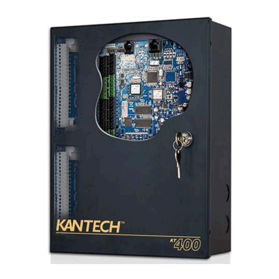
Figure 4: KT-400 cabinet for the European Union System architecture Use the KT-400 controller in various site applications with EntraPass Special, Corporate, or Global Edition. Set up the KT-400 controller with EntraPass Special or Corporate Edition Multi-site Gateway in the following ways: •... - Page 22 Figure 5: Over the internet with EntraPass Special orCorporate Edition with Multi-site Gateway Table 8: Over the internet with EntraPass Special or Corporate Edition with Multi-site Gateway Callout Description EntraPass Special Edition and Multi-site Gateway KT-100 (up to 31) RS-485 KT-400 master controller KT-300 (up to 31) Router...
- Page 23 Figure 6: USB-485 with EntraPass Special or Corporate Edition with Multi-site Gateway Table 9: USB-485 with EntraPass Special or Corporate Edition with Multi-site Gateway Callout Descriptions EntraPass Special Edition and Multi-site Gateway USB-485 RS-485 KT-400 (up to 32) KT-400 Ethernet Four-Door Controller Installation Guide...
- Page 24 Figure 7: VC-485 with EntraPass Global Edition and Global or Multi-site Gateway Table 10: VC-485 with EntraPass Global Edition and Global or Multi-site Gateway Callout Description EntraPass Global Edition with Global or Multi-site Gateway DB9 (RS-232) Note: Use the DB9F to RJ-12 adaptor (740-1022) included in the VC-485 kit. VC-485 RS-485 KT-400 (up to 32)
- Page 25 Figure 8: Over the internet with EntraPass Global Edition and a KT-NCC Table 11: Over the internet with EntraPass Global Edition and a KT-NCC Callout Description RS-485 EntraPass Global Edition KT-400 (up to 32) KT-NCC VC-485 RS-232 COM2 RS-485 COM1 RS-485 KT-400 Ethernet Four-Door Controller Installation Guide...
-
Page 26: Led Status Indicators
Figure 9: Over RS-232 from the EntraPass RS-232 COM port Table 12: Over RS-232 from the EntraPass RS-232 COM port Callout Description EntraPass Special, Corporate, or Global Edition DB9 (RS-232) Note: Use the DB9F to RJ-12 adaptor (740-1023) included in the CBLK-10 kit. The maxi- mum length for the RS-232 cable is 30 m (100 ft). -
Page 27: Heartbeat Led Patterns
Table 13: Controller LEDs Name LED color Status Heartbeat Blue The heartbeat blue LED indicates the communication status with EntraPass or the IP mode of the controller. For descriptions of the heartbeat patterns, see Table 14 Diagnostic The diagnostic red LED is used only for factory diagnostics. SPI active Yellow The SPI active LED signals activity on the SPI expansion port. -
Page 28: Technical Specifications
Table 14: Heartbeat LED Patterns Mode Flashing pattern Forced default static 3 long pulses DHCP server failed 4 long pulses Receive broadcast Single 2.5 second burst Card read or swipe Single 0.5 second burst, resume previous flash Hard reset 4 short pulses Multi-site gateway 3 short pulses Global gateway... - Page 29 Table 15: Technical specifications Type Description Cabinet weight (KT-400- 7.0 kg (15.43 lb) PCB dimension 23.11 cm (9.1 in.) x 13.97 cm (5.5 in.) x 4.06 cm (1.6 in.) Reader types Wiegand, OSDP, proximity, ABA Clock and Data, bar code, magnetic, integrated keypad, smartcard and others Reader power output 12 VDC and 5 VDC at 1A max, protected and supervised...
-
Page 30: Electrical Specifications
Electrical specifications The following table lists the electrical specifications of the KT-400 controller. Table 16: Electrical specifications Auxiliary reader outputs Maximum current (Typical) Combined maximum current LEDs (LED, OUT1 and OUT2) for 25 mA (each) 2.0 Amps for KT-400 each door reader 3.0 Amps for KT-400 EU Buzzer (BUZ) for each door 25 mA (each) - Page 31 Table 17: KT-400 controller models, expansion modules, and related items Part number Description KT-MOD-CAB KT-400 expansion module cabinet, black, with an SPI cable 91 cm (36 in.), a lock and two keys. KT-MOD-CABEU KT-400 expansion module cabinet, black, with electrical parts, an SPI Cable 91 cm (36 in.), a lock and two keys, European Union model.
-
Page 32: Kt-400 Models Information
KT-400 models information • KT-400: Cabinet with one KT-400 for North America. You can install up to two expansion modules in the cabinet. • KT-400-PCB: KT-400 with parts. • KT-400-ACC: Accessory kit. • KT-400-CAB: Cabinet only for North America. • KT-400-EU: Cabinet with KT-400, transformer, power supply and fuse terminal block for European Union. -
Page 33: Installing The Kt-400 Controller
Note: 2: A time-lag fuse of 630 mA is included with the fuse block terminal. If replacement is needed, only use recommended type (250 VA, 630 mA, Time-lag, TUV or VDE approved; it must meet EN60127-1/2/3). Installing the KT-400 controller To install the KT-400 controller, complete the following procedures. -
Page 34: Connecting Inputs
Note: If you need external power for all of the external locks, you can use an external power supply. Connect the power supply to the VIN and GND terminals and put jumper JP4 on EXT. □ When jumper JP4 is on INT, the total maximum current draw is 2 or 3 Amp, depending on the transformer main power 75VA or 100VA. -
Page 35: Connecting Devices To Inputs 1 To 16
Connecting devices to inputs 1 to 16 The KT-400 can monitor 16 onboard input points (expandable to 256 with expansion modules). Each onboard input is supervised with or without end-of-line resistors. The resistors for all inputs are 5.6K ohm, if selected. The maximum distance of one line is 600 m (2,000 ft) with AWG #22 in a single or double EOL configuration. -
Page 36: Connecting An Osdp Hid Reader
Note: The distance between the readers and the KT-400 varies by reader type. For more information, refer to the reader's installation guide. Note: To connect an ioSmart Card Reader, refer to the ioSmart Card Reader Installation Guide. Auxiliary outputs provide visual or audible access operation feedback at the controlled door. Table 19: Auxiliary outputs Door Outputs... -
Page 37: Relay Controlled Outputs
Connect the reader’s red wire to the +12VDC. Connect the reader’s black wire to the earth ground GND. Connect the reader’s RS-485-A wire/terminal to the COM2 485 +. Connect the reader’s RS-485-B wire/terminal to the COM2 485 -. Important: To ensure communication between the devices, you must configure the COM2 bus speed in both the reader and in EntraPass. -
Page 38: Auxillary Outputs
Figure 13: Relay controlled outputs Auxillary outputs □ Connect auxiliary outputs to readers and local warning devices Auxiliary outputs are used for visual and audible signals. You can activate them according to input conditions or events and local alarms. Auxiliary outputs READER DOOR 1 to 4 - LED provide visual feedback of access operations, and auxiliary outputs READER DOOR 1 to 4 - BUZ can activate audible warning devices, such as T-REX or reader buzzer, to signal door alarms. -
Page 39: Connecting The Master Controller To The Host Pc Using Rs-232
Note: Do not connect several KT-400 controllers at a single point. Do not use splitters or spider web (star) networks. Connect the RS-485 cable to (COM1) +485-. Connect the RS-485 signal ground to the 12 VDC AUX-. Note: If the 12 VDC AUX- is already in use, connect the RS-485 signal ground to the other GND terminals on the KT-400. - Page 40 Figure 15: Connecting the master controller to the host PC using RS-232 Table 20: Connecting the master controller to the host PC using RS-232 Callout Description RTS Blue GND Yellow TX Green RX Red GND Black CTS White Power RS-232 RJ-12 RS-485 If the local master controller is located more than 30 m (100 ft) from the host computer, you must...
-
Page 41: Connecting Over Corporate Network (Lan)
Figure 16: RJ-12 pin-out Table 21: RJ-12 pin-out Callout Description RTS Blue GND Yellow TX Green RX Red GND Black CTS White RJ-12 clip down RS-232 cable Adapter end Controller end Connecting over corporate network (LAN) If the master controller is used in a LAN-enabled corporate setting, use the RJ-45 Ethernet port to connect the controller to the corporate network. -
Page 42: Spi Expansion Port
WARNING: Power shall only be applied to the unit when all connections are completed and tested and unit is to be mounted and fixed on the wall. Figure 17: Powering the KT-400 controller Table 22: Powering the KT-400 controller Callout Description Black 12 V battery, 7 Ah. -
Page 43: Calculating The Spi Chain Current Draw
Figure 18: KT-400 interconnection examples with expansion modules Table 23: KT-400 interconnection examples with expansion modules Callout Description Use path A when combining input (KT-MOD-INP16) and output (KT-MOD-REL8 and KT- MOD-OUT16) modules. You must use the SPI expansion port (SPI EXP) of the first input module to add a group of output modules. -
Page 44: Rules For Installing Expansion Modules
To calculate the SPI chain current draw, use the information in the following table. Table 24: SPI chain current draw Expansion module No. of modules X maximum Total current current draw KT-MOD-REL8 _______ x 330 mA ______ mA KT-MOD-INP16 _______ x 40 mA ______ mA KT-MOD-OUT16 _______ x 750 mA... - Page 45 Table 25: Expansion modules documents list Part number Description DN1805 KT-MOD-CAB Install Sheet, French. DN1806 KT-MOD-CAB Install Sheet, English. DN1833 KT-MOD-CABEU Install Sheet, French. DN1834 KT-MOD-CABEU Install Sheet, English. DN1790 KT-MOD-INP16, KT-MOD-OUT16 and KT-MOD-REL8 expansion modules dimensions drawing. DN1792 KT-MOD-CAB dimensions drawing. DN1794 KT-MOD-CABEU dimensions drawing.
- Page 46 Figure 19: KT-MOD-INP16 KT-400 expansion module 16-zone input with SPI cable Important: The KT-MOD-INP16 SPI IN (TB1) must be connected to a KT-400 before starting a group of output modules (KT-MOD-REL8 and KT-MOD-OUT16) through the SPI expansion connector (SPI EXP). Table 26: KT-MOD-INP16 expansion module 16-zone input with SPI cable Callout Description...
- Page 47 Figure 20: KT-MOD-REL8 KT-400 expansion module 8-relay with SPI cable Table 27: KT-MOD-REL8 KT-400 expansion module 8-relay with SPI cable Callout Description SPI out: Connection to output modules only (KT-MOD-REL8 and KT-MOD-OUT16) Regulated power supply 12 VDC, 2 Amps SPI in: Connection from KT-400, from previous output module, or SPI expansion port from first KT-MOD-INP16.
- Page 48 Figure 21: KT-MOD-OUT16 KT-400 expansion module 16-output with SPI cable Table 28: KT-MOD-IO16 KT-400 expansion module 16-output with SPI cable Callout Description SPI out: Connection to output modules only (KT-MOD-REL8 and KT-MOD-OUT16). Regulated power supply 12 VDC, 2 Amps Optional external high power source 5 to 24 VDC Output device 5 to 24 VDC up to 750mA 12 VDC, up to 750 mA.
- Page 49 Figure 22: KT-MOD-IO16 RS-485 expansion module 16 input/output and SPI cable Table 29: KT-MOD-IO16 expansion module 16 input/output RS-485 and SPI cable Callout Description ioModule Output device: 12 VDC, 750 mA maximum Annunciators Relay module: 12 VDC IO #13 to IO #16 configured as generic outputs Input configuration: NC dry contact, input defined option with double EOL resistors Input configuration: NC or NO dry contact, input defined option with a single EOL resistor...
- Page 50 Table 29: KT-MOD-IO16 expansion module 16 input/output RS-485 and SPI cable Callout Description To optional SPI module IO #1 to IO #4 configured as generic ouputs Utility input Motion detector Supervised input Optional tamper switch To KT-400 RS-485 COM2 expansion modules To KT-400 12 VDC auxiliary out power or 12 VDC external power supply KT-400 Ethernet Four-Door Controller Installation Guide...
- Page 51 Figure 23: Example of KT-400 controller interconnection with expansion modules KT-400 Ethernet Four-Door Controller Installation Guide...
- Page 52 Table 30: Example of KT-400 controller interconnection with expansion modules Callout Description To KT-400 controller KT-MOD-INP16 Jumper JP5 on EXT Jumper JP5 on INT Regulated power supply, 12 VDC, 2 Amps from external source SPI OUT: Connection to other input module Regulated power supply, 12 VDC, 2 Amps from external source Jumper JP1 on INT SPI IN EXT: Connection to other output module...
- Page 53 Figure 24: KT-MOD-CAB for North America with optional expansion modules (6 maximum) KT-400 Ethernet Four-Door Controller Installation Guide...
-
Page 54: Troubleshooting
Figure 25: KT-MOD-CABEU for the European Union with optional expansion modules (4 maximum) and optional power equipment Troubleshooting Soft reset When JP2 and JP3 are ON, the controller resets on a) power up, b) pushbutton, or c) EntraPass software manual operator soft reset. •... - Page 55 • With a global gateway, the internal event buffer clears. • The IP address is kept if valid. • The controller generates the appropriate message: a) Power ON Soft Reset, b) Manual Pushbutton Soft Reset, or c) Operator Soft Reset. Table 31: Soft reset Jumpers Heartbeat...
-
Page 56: Default Initialization
• The Ethernet port resets to DHCP configuration and waits for an IP address from the local DHCP server. • The internal RTC and clock reset to the default time and date values: January 1st 2005, 00:00:00, Saturday. Table 34: Forced default DHCP Jumpers Heartbeat Pattern... - Page 57 To reset the controller to factory default DHCP, complete the following steps: Remove jumpers JP2 and JP3. For more information about factory default DHCP mode, see Troubleshooting. Press the Reset button. Check the blue heartbeat LED pattern. Verify the IP address using the KT-Finder. For more information, see Configuring the KT-400 using the KT-Finder.
-
Page 58: Kt-400 Maintenance Recommendations
KT-400 maintenance recommendations Important: Only a service person shall perform the following maintenance. The KT-400 includes a lithium CR2032 primary battery. See Figure 1. This battery must be replaced by a service person ONLY to avoid any risk of explosion. If the lithium battery stops working, contact the service person for maintenance if the lithium battery voltage measures below 2.75 VDC. -
Page 59: Activating Standalone Mode
Figure 27: KT-400 online interface Activating standalone mode On the KT-400 online interface, click Standalone. On the Activate now tab, in the Customer information and Installer information fields, enter the relevant information. Click Activate now. Figure 28: Activating standalone mode Note: The product is not UL listed when used in standalone mode. -
Page 60: Activating Entrapass Mode
Figure 29: Other ways to activate standalone mode Activating EntraPass mode On the KT-400 online interface, click EntraPass. In the EntraPass gateway pane, in the IP address field, enter the IP address, or in the Domain name field, enter the domain name. From the Protocol list, select TCP or UDP. - Page 61 Figure 30: KT-Finder device connection window When the KT-400 is found, the configuration page displays. Put jumpers on JP2 and JP3 Figure 31: KT-Finder configuration window KT-400 Ethernet Four-Door Controller Installation Guide...
- Page 62 In your KT-Finder Wizard window, enter the EntraPass IP address or the Domain name of the EntraPass Gateway. This information must be the same as entered in the EntraPass workstation for Devices > Site. Select Obtain an IP address automatically or Use the following IP address. This information must be the same as entered in the EntraPass workstation for Devices >...
-
Page 63: Network Configuration Information Sheet
Network configuration information sheet Company name: Site name: □ LAN □ WAN (see other side) Figure 32: Configuration in a local area network (LAN) Table 36: Configuration in a local area network (LAN) Callout Description EntraPass workstation EntraPass Multi-Site Gateway Router KT-400 controller For more information, refer to the EntraPass Administrative Guide. - Page 64 □ Static IP address: ______.______.______.______ Subnet mask: ______.______.______.______ Default Gateway (Router): ______.______.______.______ EntraPass Special Edition / Multi-site Gateway IP address: ______.______.______.______ Figure 33: Configuration in a wide area network (WAN) Note: Ethernet connections are not to be used for off-premise communication in UL installations.
- Page 65 For more information, refer to the EntraPass Administrative Guide. EntraPass Gateway Ports: □ 18001 (UDP) and □ 18801 (UDP) or 18802 (TCP) KT-400 Ethernet Four-Door Controller site MAC address: 00:50:F9: ______:______:______ IP address type: □ Static or □ Reserved DHCP IP address: ______.______.______.______ Subnet mask: ______.______.______.______ Default Gateway (Router): ______.______.______.______...
-
Page 66: Installation Checklist
Installation checklist To the installer: if you are familiar with the installation, you can use the checklist with the □ symbol. Preparing to install the KT-400 controller □ Required to install KT-400 Ethernet Four-Door Controller Physical installation □ Check for ideal indoor location □... -
Page 67: Powering The Kt-400 Controller
Powering the KT-400 controller □ Install the transformer or DC power supply, if applicable □ Place the battery in cabinet □ Connect the battery □ Power up the KT-400 Ethernet Four-Door Controller KT-400 Ethernet Four-Door Controller Installation Guide... -
Page 68: Inputs And Outputs Assignments Sheet
Inputs and outputs assignments sheet Doors DOOR 1 CONTACT DOOR 2 CONTACT DOOR 3 CONTACT DOOR 4 CONTACT Inputs DOOR Z1 NO or NC EOL, DRY or DEOL REX Z2 NO or NC EOL, DRY or DEOL INPUT Z3 NO or NC EOL, DRY or DEOL INPUT Z4 NO or NC... - Page 69 Figure 34: KT-400 cabinet inner door sticker (North America) KT-400 Ethernet Four-Door Controller Installation Guide...
- Page 70 Figure 35: KT-400-EU inner door sticker (European Union) KT-400 Ethernet Four-Door Controller Installation Guide...
-
Page 71: Compliance Specifications
Compliance specifications To comply with UL listings, the following requirements must be met: • Use of a UL listed computer • Use of UL listed readers (Wiegand 26 and 34 bits, mag stripe 26 and 34 bits, XSF 39 bits have been tested and found to comply) •... -
Page 72: Ul 1076 Compliance Notice
UL 1076 compliance notice • The KT-400 is UL 1076 Listed as a Commercial Proprietary Control Unit Accessory and Proprietary Burglar Alarm Unit (Section 83.2), with EntraPass and Redundant Server, alarm system features, KT-300 Controllers, ioProx Proximity readers, and T.Rex request to exit devices –... -
Page 73: Fcc & Icc
• For certified commercial proprietary control unit accessory applications, the requirements of UL 1076, Commercial Proprietary Control Unit Accessory also apply. • Use Kantech part number KT-3LED-PLATE 3-color LED indicators mounted on single plate when the KT-400 is configured with the (APOU/ALVY) KT-NCC in an EntraPass Global Edition system for remote alarm monitoring. -
Page 74: Ce And Ukca
CE and UKCA European Union: KT-400-EU complies with Electromagnetic Compatibility Directive, Low Voltage Directive, and Waste Electrical and Electronic Equipment Directive. United Kingdom: Electromagnetic Compatibility Regulations, The Electrical Equipment (Safety) Regulations, and Restriction of the Use of Certain Hazardous Substances in Electrical and Electronic Equipment Regulations. - Page 75 • Alerts annunciation at the monitoring console (EntraPass) shall be programmed to occur when a tamper condition is generated, an access point is opened without granted access or if the access point remains open longer than the allowed period of time. •...
-
Page 76: Appendix
Appendix Security hardening guide The security hardening guide provides information about the following areas: • Assuring compliance with the cybersecurity criteria that govern the target environment • Designing safe and secure deployment architecture • Providing a reference for settings that you configure during deployment To ensure the safe and secure deployment of the KT-400 controller, complete the following steps: Ensure that you understand and plan your controller architecture. -
Page 77: Updating To The Latest Firmware
Connecting a stand-alone controller using Ethernet • To connect a stand-alone controller, configure your username and password. Use these details to access the secure Kantech registration web pages to configure the controller. Note: Complete this process during the initial setup. Connecting readers and modules using Wiegand and an SPI The Wiegand connections and SPI connection are not encrypted or authenticated. -
Page 78: Protecting The Network
• To execute the proper hardening steps, you must have experience with KT-400 administration and networking technologies. To gain the required competencies, complete the basic and advanced Kantech installation courses. For more information, refer to http:// www.kantech.com. © 2022 Johnson Controls. All rights reserved.
Need help?
Do you have a question about the Tyco Kantech KT-400 and is the answer not in the manual?
Questions and answers