Table of Contents
Advertisement
Quick Links
Advertisement
Chapters
Table of Contents

Related Manuals for Rohde & Schwarz ZNL4


Summary of Contents for Rohde & Schwarz ZNL4
- Page 1 ® R&S ZNL/ZNLE Vector Network Analyzers User Manual (;ÜÉÐ2) 1178596602 Version 13...
- Page 2 ZNL3, 5 kHz to 3 GHz, 2 ports, N(f) connectors, order no. 1323.0012.03 ● ® R&S ZNL4, 5 kHz to 4.5 GHz, 2 ports, N(f) connectors, order no. 1323.0012.04 ● ® R&S ZNL6, 5 kHz to 6 GHz, 2 ports, N(f) connectors, order no. 1323.0012.06 ●...
-
Page 3: Table Of Contents
® Contents R&S ZNL/ZNLE Contents 1 Safety and Regulatory Information............ 13 Safety Instructions......................13 Labels on R&S ZNL/ZNLE..................16 Korea Certification Class A..................17 2 Documentation Overview..............18 Getting Started Manual....................18 User Manuals and Help....................18 Service Manual......................18 Instrument Security Procedures................19 Basic Safety Instructions................... 19 Data Sheets and Brochures.................. - Page 4 ® Contents R&S ZNL/ZNLE 4.1.12 Checking the Supplied Options..................37 4.1.13 Considerations for Test Setup..................38 Instrument Tour......................39 4.2.1 Front Panel View......................39 4.2.2 Rear Panel View......................46 Trying Out the Instrument..................52 4.3.1 Performing Measurements....................52 4.3.2 Zooming into the Display....................59 4.3.3 Saving Settings......................
- Page 5 ® Contents R&S ZNL/ZNLE 6.2.3 How to Save and Load Instrument Settings..............104 Creating Screenshots of Current Measurement Results and Settings....106 6.3.1 Print and Screenshot Settings..................106 6.3.2 How to Store or Print Screenshots of the Display............116 7 General Instrument Setup..............119 Reference Frequency....................119 Display Settings......................
- Page 6 ® Contents R&S ZNL/ZNLE VISA Libraries......................156 Network and Remote Control Settings..............156 8.4.1 General Network Settings................... 157 8.4.2 Remote Settings......................158 8.4.3 Compatibility Settings....................161 8.4.4 LAN Settings....................... 162 8.4.5 Remote Errors......................163 8.4.6 Returning to Manual Mode ("Local")................165 How to Set Up a Network and Remote Control............166 8.5.1 How to Configure a Network..................
- Page 7 ® Contents R&S ZNL/ZNLE 9.3.4 Admittance Parameters....................224 9.3.5 Wave Quantities and Ratios..................225 9.3.6 Unbalance-Balance Conversion..................227 9.3.7 Stability Factors......................230 9.3.8 Delay, Aperture, Electrical Length................230 Operations on Traces....................231 9.4.1 Limit Check......................... 231 9.4.2 Trace Files........................238 9.4.3 Memory-Mapped Trace Data Transfer................ 247 Calibration.........................
- Page 8 ® Contents R&S ZNL/ZNLE 10 VNA GUI Reference................294 10.1 Function Keys and Softtools................... 294 10.2 Stimulus Softtool...................... 295 10.2.1 Stimulus Tab........................296 10.2.2 Power Tab........................297 10.2.3 Time Domain X-Axis Tab.....................299 10.3 Scale Softtool......................300 10.3.1 Scale Values Tab......................301 10.3.2 Scale Coupling Tab..................... 303 10.3.3 Zoom Tab........................
- Page 9 ® Contents R&S ZNL/ZNLE 10.7.2 Ratios Tab........................383 10.7.3 Wave Tab........................386 10.7.4 Z←Sij Tab........................388 10.7.5 Y←Sij Tab........................390 10.7.6 Y-Z-Params Tab......................392 10.7.7 Stability Tab.........................394 10.8 Format Softtool......................395 10.9 Display Lines Softtool....................401 10.9.1 Diagram Tab........................402 10.9.2 Split Tab........................405 10.9.3 Config Tab........................
- Page 10 ® Contents R&S ZNL/ZNLE 10.13.2 Mode Tab........................487 10.13.3 Channel Bits Tab......................489 10.14 Offset Embed Softtool....................490 10.14.1 Offset Embed Dock Widget..................490 10.14.2 Offset Tab........................499 10.14.3 One Way Loss Tab...................... 505 10.14.4 Single Ended Tab......................507 10.14.5 Port Sets Tab.......................510 10.14.6 Balanced Tab......................
- Page 11 ® Contents R&S ZNL/ZNLE 12 Troubleshooting................1003 12.1 Error Messages and Troubleshooting..............1003 12.1.1 Errors during Firmware Operation................1003 12.1.2 Errors during Firmware Installation/Update...............1005 12.2 System Recovery....................1005 12.3 Collecting Information for Support................1006 12.4 Contacting Customer Support................1007 13 Transporting..................1009 14 Maintenance, Storage, Transport and Disposal......1010 14.1 Cleaning........................
- Page 12 ® Contents R&S ZNL/ZNLE User Manual 1178.5966.02 ─ 13...
-
Page 13: Safety And Regulatory Information
® Safety and Regulatory Information R&S ZNL/ZNLE Safety Instructions 1 Safety and Regulatory Information The product documentation helps you use the product safely and efficiently. Follow the instructions provided here and in the Chapter 1.1, "Safety Instructions", on page 13. Intended use The product is intended for the development, production and verification of electronic components and devices in industrial, administrative, and laboratory environments. - Page 14 ® Safety and Regulatory Information R&S ZNL/ZNLE Safety Instructions Choosing the operating site Only use the product indoors. The product casing is not waterproof. Water that enters can electrically connect the casing with live parts, which can lead to electric shock, serious personal injury or death if you touch the casing.
- Page 15 ® Safety and Regulatory Information R&S ZNL/ZNLE Safety Instructions ● If the product needs an external power supply, use the power supply that is deliv- ered with the product or that is recommended in the product documentation or a power supply that conforms to the country-specific regulations. ●...
-
Page 16: Labels On R&S Znl/Znle
® Safety and Regulatory Information R&S ZNL/ZNLE Labels on R&S ZNL/ZNLE ● Do not expose the battery to high temperatures such as open flames, hot surfaces and sunlight. ● Only use the battery with the designated Rohde & Schwarz product. ●... -
Page 17: Korea Certification Class A
® Safety and Regulatory Information R&S ZNL/ZNLE Korea Certification Class A 1.3 Korea Certification Class A 이 기기는 업무용(A급) 전자파 적합기기로서 판매자 또는 사용자는 이 점을 주의하시기 바라며, 가정외의 지역에서 사용하는 것을 목적으로 합니다. User Manual 1178.5966.02 ─ 13... -
Page 18: Documentation Overview
® Documentation Overview R&S ZNL/ZNLE Service Manual 2 Documentation Overview This section provides an overview of the R&S ZNL/ZNLE user documentation. Unless specified otherwise, you find the documents on the R&S ZNL/ZNLE product page at: www.rohde-schwarz.com/manual/ZNL or www.rohde-schwarz.com/manual/ZNLE. 2.1 Getting Started Manual Introduces the R&S ZNL/ZNLE and describes how to set up and start working with the product. -
Page 19: Instrument Security Procedures
® Documentation Overview R&S ZNL/ZNLE Release Notes and Open Source Acknowledgment (OSA) https://gloris.rohde-schwarz.com/irj/portal/SearchDetailView?downloadContai- nerID=484937 ZNL service manual, ZNLE service manual 2.4 Instrument Security Procedures Deals with security issues when working with the R&S ZNL/ZNLE in secure areas. It is available for download on the Internet. 2.5 Basic Safety Instructions Contains safety instructions, operating conditions and further important information. -
Page 20: Application Notes, Application Cards, White Papers, Etc
® Documentation Overview R&S ZNL/ZNLE Calibration Certificate 2.8 Application Notes, Application Cards, White Papers, etc. These documents deal with special applications or background information on particu- lar topics. www.rohde-schwarz.com/application/ZNL www.rohde-schwarz.com/application/ ZNLE. 2.9 Calibration Certificate The document is available on https://gloris.rohde-schwarz.com/calcert. You need the device ID of your instrument, which you can find on a label on the rear panel. -
Page 21: What's New In Firmware Version 1.41
® What's New in Firmware Version 1.41 R&S ZNL/ZNLE Firmware Version 1.40 3 What's New in Firmware Version 1.41 This section lists the changes introduced in the current version of the R&S ZNL/ZNLE firmware. Software version ► To check your R&S ZNL/ZNLE "Instrument Firmware" and "VNA Server" version, select [SETUP] >... - Page 22 ® What's New in Firmware Version 1.41 R&S ZNL/ZNLE Firmware Version 1.40 ® – R&S ZNLE14, 1 MHz* to 14 GHz, 2 ports, N(f) connectors, order no. 1323.0012.64 ® – R&S ZNLE18, 1 MHz* to 18 GHz, 2 ports, N(f) connectors, order no.
- Page 23 ® What's New in Firmware Version 1.41 R&S ZNL/ZNLE Firmware Version 1.40 Spectrum analysis changes (R&S ZNL only) The spectrum analysis function of the R&S ZNL (with hardware option B1) and its addi- tional software options are based on firmware 1.70 of the Rohde & Schwarz spectrum analyzer R&S FPL1000.
-
Page 24: Getting Started
® Getting Started R&S ZNL/ZNLE Preparing for Use 4 Getting Started 4.1 Preparing for Use Here, you can find basic information about setting up the instrument for the first time. ● Lifting and Carrying....................24 ● Unpacking and Checking..................24 ●... -
Page 25: Setting Up The R&S Znl/Znle
® Getting Started R&S ZNL/ZNLE Preparing for Use See also "Choosing the operating site" on page 14. Electromagnetic compatibility classes The electromagnetic compatibility (EMC) class indicates where you can operate the product. The EMC class of the product is given in the data sheet under "General data". ●... - Page 26 ® Getting Started R&S ZNL/ZNLE Preparing for Use As an alternative, you can mount several products in a rack. 4. NOTICE! Overheating can damage the product. Prevent overheating as follows: ● Keep a minimum distance of 10 cm between the fan openings of the product and any object in the vicinity.
-
Page 27: Connecting To Power
® Getting Started R&S ZNL/ZNLE Preparing for Use 3. If placing the R&S ZNL/ZNLE on a bench top again, unmount the adapter kit from the R&S ZNL/ZNLE. Follow the instructions provided with the adapter kit. 4.1.4.3 Portable Operation An optional carrying bag designed specifically for the R&S ZNL allows you to protect the instrument while working in the field. - Page 28 ® Getting Started R&S ZNL/ZNLE Preparing for Use ● The R&S ZNL allows for battery operation if option R&S FPL1-B31 is installed. 4.1.5.1 Connecting the AC Power The R&S ZNL/ZNLE can be used with different AC power voltages and adapts itself automatically to it.
- Page 29 ® Getting Started R&S ZNL/ZNLE Preparing for Use DC connection ► Connect the DC power connector on the rear panel of the R&S ZNL to the DC power source using a cable as described above. 4.1.5.3 Optional Battery Pack (R&S FPL1-B31) As an alternative to the fixed AC or DC power supply, the R&S ZNL also allows for bat- tery operation.
-
Page 30: Switching On Or Off
® Getting Started R&S ZNL/ZNLE Preparing for Use Remote command to determine the battery charge state: on page 571 DIAGnostic:SERVice:BATTery:LEVel? Spare battery pack (R&S FPL1-Z4) In addition to the internal battery pack (option R&S FPL1-B31), spare batteries are available for the R&S ZNL. The spare battery pack R&S FPL1-Z4 comprises two addi- tional Li-ion batteries. -
Page 31: Connecting To Lan
® Getting Started R&S ZNL/ZNLE Preparing for Use To shut down the product The product is in the ready state. ► Press the [Power] key. The operating system shuts down. The LED changes to orange. To disconnect from power The R&S ZNL/ZNLE is in the standby state. 1. -
Page 32: Connecting A Keyboard
® Getting Started R&S ZNL/ZNLE Preparing for Use Consult your network administrator before performing the following tasks: ● Connecting the instrument to the network ● Configuring the network ● Changing IP addresses ● Exchanging hardware Errors can affect the entire network. Connect the R&S ZNL/ZNLE to the LAN via the LAN interface on the rear panel of the instrument. - Page 33 ® Getting Started R&S ZNL/ZNLE Preparing for Use Screen resolution and format The touchscreen of the R&S ZNL/ZNLE is calibrated for a 16:10 format. If you connect a monitor or projector using a different format (e.g. 4:3), the calibration is not correct and the screen does not react to your touch actions properly.
-
Page 34: Windows Operating System
® Getting Started R&S ZNL/ZNLE Preparing for Use ● "Duplicate" : both internal and external monitor 7. Tap "Apply" to try out the settings before they are accepted permanently, then you can easily return to the previous settings, if necessary. 8. - Page 35 ® Getting Started R&S ZNL/ZNLE Preparing for Use only required when peripherals like a keyboard or a printer are installed or if the net- work configuration does not comply with the default settings. After the R&S ZNL/ZNLE is started, the operating system boots and the instrument firmware is started automati- cally.
-
Page 36: Logging On
® Getting Started R&S ZNL/ZNLE Preparing for Use To access the "Start" menu The Windows "Start" menu provides access to the Windows functionality and installed programs. ► Select the "Windows" icon in the toolbar, or press the "Windows" key or the [CTRL + ESC] key combination on the (external) keyboard. -
Page 37: Checking The Supplied Options
® Getting Started R&S ZNL/ZNLE Preparing for Use Changing the password and use of auto-login function Note that when you change the default password, the default auto-login function no longer works! In this case, you must enter the new password manually to log on. Adapting the auto-login function to a new password If you change the password that is used during auto-login, this function no longer works. -
Page 38: Considerations For Test Setup
® Getting Started R&S ZNL/ZNLE Preparing for Use 1. Press the [SETUP] key. 2. Press the "System Config" softkey. 3. Switch to the "Versions + Options" tab in the "System Configuration" dialog box. A list with hardware and firmware information is displayed. 4. -
Page 39: Instrument Tour
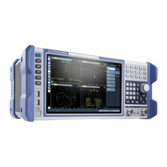
® Getting Started R&S ZNL/ZNLE Instrument Tour 4.2 Instrument Tour 4.2.1 Front Panel View This chapter describes the front panel, including all function keys and connectors. Figure 4-1: Front panel view 1 = Power key 2 = USB (2.0) connectors 3 = System keys 4 = Touchscreen 5 = Function keys... - Page 40 ® Getting Started R&S ZNL/ZNLE Instrument Tour Figure 4-2: Touchscreen elements 1 = Toolbar with standard application functions, e.g. print, save/open file etc. 2 = Tabs for individual channel setups 3 = Softtool panel (a.k.a. softkey bar) 4 = Window title bar with diagram-specific (trace) information 5 = Measurement results (diagram) area 6 = Channel list 7 = Diagram footer with diagram-specific information...
- Page 41 ® Getting Started R&S ZNL/ZNLE Instrument Tour 4.2.1.2 Power Key The [Power] key is located on the lower left corner of the front panel. It starts up and shuts down the instrument. See also "Connecting to power" on page 14 and Chapter 4.1.5, "Connecting to Power", on page 27.
- Page 42 ® Getting Started R&S ZNL/ZNLE Instrument Tour 4.2.1.5 Function Keys Function keys provide access to the most common measurement settings and func- tions. A detailed description of the corresponding functions is provided in the R&S ZNL/ZNLE user manual. The labels indicated in italics (blue font color on the instrument) apply to the optional Spectrum mode only.
- Page 43 ® Getting Started R&S ZNL/ZNLE Instrument Tour Function key Assigned functions VNA mode SA mode (R&S ZNL only) [Offset Embed] Contains functions for deembedding/ Performs a peak search for active embedding the DUT from/into physical/ marker. If no marker is active, normal virtual (matching) networks placed marker 1 is activated and the peak between the calibrated reference plane...
- Page 44 ® Getting Started R&S ZNL/ZNLE Instrument Tour Type of key Description If an alphanumeric entry has already been started, this key deletes the character to the left of the cursor. (BACKSPACE) ● [ENTER] Concludes the entry of dimensionless entries. The new value is accepted.
- Page 45 ® Getting Started R&S ZNL/ZNLE Instrument Tour Arrow Left/Arrow Right Keys The <arrow left> or <arrow right> keys do the following: ● In an alphanumeric edit dialog box, move the cursor. ● In a list, scroll forward and backward through the list entries. ●...
-
Page 46: Rear Panel View
® Getting Started R&S ZNL/ZNLE Instrument Tour For the R&S ZNLE, the Spectrum mode is not available and hence this connector is always used as VNA port 2. See also Chapter 4.1.13, "Considerations for Test Setup", on page 38. 4.2.2 Rear Panel View This figure shows the rear panel view of the R&S ZNL/ZNLE. - Page 47 ® Getting Started R&S ZNL/ZNLE Instrument Tour Figure 4-4: Rear panel view R&S ZNLE 1 = AC power supply connection and main power switch 2 = GPIB ("IEC") interface 3 = Reference clock connectors 4 = Trigger input connector 5 = "DVI" connector for external display 6 = "LAN"...
- Page 48 ® Getting Started R&S ZNL/ZNLE Instrument Tour For safety information concerning batteries, see "Handling batteries safely" on page 15. As an alternative, a DC power supply connector (option R&S FPL1-B30) is available. DC power supplies from +12 V to +24 V and from 13 A to 6.5 A can be used. Connect the connector according to the following diagram: Description Plus...
- Page 49 ® Getting Started R&S ZNL/ZNLE Instrument Tour Connector Reference signal Usage Ref. In 10 MHz To provide an external reference signal on the R&S ZNL/ZNLE. 10 dBm Ref. Out 10 MHz To provide the internal reference signal from the R&S ZNL/ZNLE to another device continuously. 10 dBm For the R&S ZNL, this is also used to provide the optional OCXO reference signal to another device.
- Page 50 ® Getting Started R&S ZNL/ZNLE Instrument Tour ● This connector is provided by the "Additional Interfaces" option R&S FPL1-B5. This option is not available for the R&S ZNLE. ● The IF/Video Output interface is only functional in Spectrum mode (option R&S ZNL3|4|6-B1) ●...
- Page 51 ® Getting Started R&S ZNL/ZNLE Instrument Tour ● This connector is provided by the "Additional Interfaces" option R&S FPL1-B5. This option is not available for the R&S ZNLE. ● The headphones connector is only functional in Spectrum mode (option R&S ZNL3|4|6-B1). It can not be used to output sounds that are generated via Windows audio APIs.
-
Page 52: Trying Out The Instrument
® Getting Started R&S ZNL/ZNLE Trying Out the Instrument 4.2.2.14 Device ID The unique device identifier is provided as a barcode sticker on the rear panel of the R&S ZNL/ZNLE. It consists of the device order number and a serial number. The serial number is used to define the default instrument name, which is: <Type><variant>-<serial_number>... - Page 53 ® Getting Started R&S ZNL/ZNLE Trying Out the Instrument Safety considerations Before starting any measurement on your network analyzer, please note the instruc- tions given in Chapter 4.1, "Preparing for Use", on page 24. Use the "S-Parameter Wizard" accessible via [Meas] > "S-Params" > "S-Param Wiz- ard..."...
- Page 54 ® Getting Started R&S ZNL/ZNLE Trying Out the Instrument 1. Connect the DUT between test ports 1 and 2 of the network analyzer as shown above. 2. Switch on the instrument and start the VNA application. Proceed as described in Chapter 4.1.6, "Switching On or Off", on page 30.
- Page 55 ® Getting Started R&S ZNL/ZNLE Trying Out the Instrument By default the sweep range is set to the frequency range of the analyzer, which can be unsuitable for your DUT. The following procedure shows you how to configure a smaller sweep range. 1.
- Page 56 ® Getting Started R&S ZNL/ZNLE Trying Out the Instrument Due to the R&S ZNL/ZNLE's calibration wizard, calibration is a straightforward, guided process. 1. Replace the DUT by the Through standard of your calibration kit. Make sure to dis- connect all calibration units. 2.
- Page 57 ® Getting Started R&S ZNL/ZNLE Trying Out the Instrument 7. The calibration dock widget indicates the standard measurements that make up a "Trans Norm" calibration. Select "Through (mm)" to initiate the measurement of the connected Through stan- dard. Measuring the isolation between ports 1 and 2 is optional. Skip it for now. The analyzer performs a calibration sweep for the measured quantity S .
- Page 58 ® Getting Started R&S ZNL/ZNLE Trying Out the Instrument corner of the diagram. The marker info field displays the stimulus value (frequency) and response value (magnitude of the transmission coefficient converted to a dB value) at the marker position. 2. Open the [Mkr->] > "Peak" softtool tab and activate "Min" search. The marker jumps to the absolute minimum of the curve in the entire sweep range.
-
Page 59: Zooming Into The Display
® Getting Started R&S ZNL/ZNLE Trying Out the Instrument In principle, a reflection measurement involves the same steps as a transmission mea- surement. Note the following differences: ● The basic test setup for reflection measurements involves a single DUT and ana- lyzer port. -
Page 60: Saving Settings
® Getting Started R&S ZNL/ZNLE Trying Out the Instrument 1. Tap the "Multiple Zoom" icon in the toolbar. The icon is highlighted to indicate that zoom mode is active. 2. Tap the diagram near the peak and drag your finger to the opposite corner of the zoom area. - Page 61 ® Getting Started R&S ZNL/ZNLE Trying Out the Instrument 3. In the "Save" dialog box, tap the "File name" field and enter MyMultiViewSetup using the keyboard. Keep the default "File Type" setting "Instrument with all Channel Setups" to store the configuration of all channel setups. Figure 4-7: Saving the instrument settings to a file 4.
-
Page 62: Printing And Saving Results
® Getting Started R&S ZNL/ZNLE Trying Out the Instrument 4. Tap the "Load" button. All instrument settings are restored and the display should resemble the instrument display right before the settings were stored. 4.3.4 Printing and Saving Results Finally, after a successful measurement, we will document our results. First we will export the numeric trace data, then we will create a screenshot of the graphical display. -
Page 63: Activating Additional Channel Setups
® Getting Started R&S ZNL/ZNLE Trying Out the Instrument 4.3.5 Activating Additional Channel Setups The R&S ZNL/ZNLE features multiple channel setups, i.e. you can define several mea- surement configurations in parallel and then switch between the channel setups auto- matically to perform the measurements sequentially. We will demonstrate this feature by activating additional channel setups for a different frequency range, a Spectrum measurement, and an I/Q analysis (note that the latter two measurements are only available if the optional Spectrum mode is installed). - Page 64 ® Getting Started R&S ZNL/ZNLE Trying Out the Instrument Figure 4-8: Adding a new channel setup 6. Create a new channel setup for I/Q analysis: a) Press the [Mode] key. b) Tap the "IQ Analyzer" button to activate a channel setup for the I/Q Analyzer application.
-
Page 65: Trying Out Spectrum Mode
® Getting Started R&S ZNL/ZNLE Trying Out the Instrument The "IQ Analyzer" channel setup displays the real and imaginary signal parts in separate windows. To display the MultiView tab An overview of all active channel setups is provided in the "MultiView" tab. This tab is always displayed if more than one channel setup is active and cannot be closed. - Page 66 ® Getting Started R&S ZNL/ZNLE Trying Out the Instrument ● Measuring a Basic Signal..................66 ● Displaying a Spectrogram..................68 ● Setting and Moving a Marker.................. 70 ● Displaying a Marker Peak List.................71 4.3.6.1 Measuring a Basic Signal We will start out by measuring a simple sinus wave, using the internal calibration signal as the input.
- Page 67 ® Getting Started R&S ZNL/ZNLE Trying Out the Instrument Instrument warmup time Note that the instrument requires an initial warmup time after switching it on. A mes- sage in the status bar ("Instrument warming up...") indicates that the operating temper- ature has not yet been reached.
- Page 68 ® Getting Started R&S ZNL/ZNLE Trying Out the Instrument Figure 4-12: Calibration signal with optimized display settings 4.3.6.2 Displaying a Spectrogram In addition to the standard "level versus frequency" spectrum display, the R&S ZNL/ ZNLE also provides a spectrogram display of the measured data. A spectrogram shows how the spectral density of a signal varies over time.
- Page 69 ® Getting Started R&S ZNL/ZNLE Trying Out the Instrument Figure 4-13: Adding a Spectrogram to the display Drop the icon. 4. Close the SmartGrid mode by tapping the "Close" icon at the top right corner of the toolbar. You see the spectrogram compared to the standard spectrum display. Since the calibration signal does not change over time, the color of the frequency levels does not change over time, i.e.
- Page 70 ® Getting Started R&S ZNL/ZNLE Trying Out the Instrument Figure 4-14: Spectrogram of the calibration signal 4.3.6.3 Setting and Moving a Marker Markers are useful to determine the position of particular effects in the trace. The most common use is to determine a peak, which is the default setting when you activate a marker.
- Page 71 ® Getting Started R&S ZNL/ZNLE Trying Out the Instrument 6. Now you can move the marker by tapping and dragging it to a different position. The current position is indicated by a dotted blue line. Notice how the position and value change in the marker area of the diagram.
-
Page 72: Performing Sequential Measurements
® Getting Started R&S ZNL/ZNLE Trying Out the Instrument 6. To obtain a more conclusive peak list that does not contain noise peaks, for exam- ple, define a threshold that is higher than the noise floor: a) Press the [MKR] key on the front panel. b) Tap the "Marker Config"... -
Page 73: Operating The Instrument
® Getting Started R&S ZNL/ZNLE Operating the Instrument Figure 4-16: "MultiView" tab with active Sequencer Figure 4-16, the "Spectrum 2" measurement is currently active (indicated by the "channel active" icon in the tab label). 3. Stop the Sequencer by tapping the "Sequencer" softkey again. 4.4 Operating the Instrument This chapter provides an overview on how to work with the R&S ZNL/ZNLE. -
Page 74: Understanding The Display Information (Vna Mode)
® Getting Started R&S ZNL/ZNLE Operating the Instrument ● Understanding the Display Information (VNA Mode)..........74 ● Accessing the Functionality..................75 ● Entering Data......................80 ● Touchscreen Gestures.................... 81 ● Getting Help......................84 4.4.1 Understanding the Display Information (VNA Mode) The following figure shows a measurement diagram in VNA mode. All different infor- mation areas are labeled. -
Page 75: Accessing The Functionality
® Getting Started R&S ZNL/ZNLE Operating the Instrument 1 = Trace name 2 = Measured parameter 3 = Trace format 4 = Scale per division 5 = Reference value Diagram footer For each parameter diagram, a window is displayed with the following information in the footer: 1 = Channel 2 = Center frequency... - Page 76 ® Getting Started R&S ZNL/ZNLE Operating the Instrument 4.4.2.1 Toolbar Functions Standard functions can be performed via the icons in the toolbar at the top of the screen. You can hide the toolbar display, e.g. when using remote control, to enlarge the display area for the measurement results ("Setup"...
- Page 77 ® Getting Started R&S ZNL/ZNLE Operating the Instrument Note: The [UNDO] function is not available after a [PRESET] or "Recall" operation. When these functions are used, the history of previous actions is deleted. Redo Repeats previously reverted operation Zoom mode Displays a dotted rectangle in the diagram that can be expanded to define the zoom area.
- Page 78 ® Getting Started R&S ZNL/ZNLE Operating the Instrument Figure 4-17: Scale softtool The softtools are displayed in the softkey bar of the instrument. The title area of the softkey bar displays the name of the currently opened softtool. If you close the softkey bar using its close icon, it is automatically reopened the next time a function key is pressed.
- Page 79 ® Getting Started R&S ZNL/ZNLE Operating the Instrument 4.4.2.4 On-screen Keyboard The on-screen keyboard is an additional means of interacting with the instrument with- out having to connect an external keyboard. The on-screen keyboard display can be switched on and off as desired using the "On- Screen Keyboard"...
-
Page 80: Entering Data
® Getting Started R&S ZNL/ZNLE Operating the Instrument You can use the TAB key on the on-screen keyboard to move the focus from one field to another in dialog boxes. 4.4.3 Entering Data Data can be entered in dialog boxes using one of the following methods: ●... -
Page 81: Touchscreen Gestures
® Getting Started R&S ZNL/ZNLE Operating the Instrument Entering Alphanumeric Parameters If a field requires alphanumeric input, you can use the on-screen keyboard to enter numbers and (special) characters (see Chapter 4.4.2.4, "On-screen Keyboard", on page 79). Correcting an entry 1. - Page 82 ® Getting Started R&S ZNL/ZNLE Operating the Instrument Dragging Move your finger from one position to another on the display, keeping your finger on the display the whole time. By dragging your finger over a table or diagram you can pan the displayed area of the table or diagram to show results that were previously out of view.
- Page 83 ® Getting Started R&S ZNL/ZNLE Operating the Instrument Figure 4-21: Spreading Touch gestures in diagrams change measurement settings When you change the display using touch gestures, the corresponding measurement settings are adapted. This is different to selecting an area on the screen in zoom mode, where merely the resolution of the displayed trace points is changed temporarily (graphical zoom).
-
Page 84: Getting Help
® Getting Started R&S ZNL/ZNLE Operating the Instrument 4.4.5 Getting Help If any questions or problems concerning the R&S ZNL/ZNLE arise, an extensive online help system is provided on the instrument and can be consulted at any time. The help system is context-sensitive and provides information specifically for the current opera- tion or setting to be performed. -
Page 85: Operating Modes, Applications, Channel Setups, And Result Displays
® Operating Modes, Applications, Channel Setups, and Result Displays R&S ZNL/ZNLE 5 Operating Modes, Applications, Channel Setups, and Result Displays If the "Spectrum Analysis" hardware option B1 is installed, the R&S ZNL is actually two instruments in one: a vector network analyzer (VNA) and a spectrum analyzer (SA). The R&S ZNL integrates the functionality of the two as separate operating modes in one instrument. -
Page 86: Available Applications
® Operating Modes, Applications, Channel Setups, and Result Displays R&S ZNL/ZNLE Available Applications ● Available Applications..................... 86 ● R&S MultiView......................87 ● Defining Channel Setups..................88 ● Running a Sequence of Measurements..............90 5.1 Available Applications Access: [Mode] Without the spectrum analysis hardware option B1, the R&S ZNL only provides the application. -
Page 87: R&S Multiview
® Operating Modes, Applications, Channel Setups, and Result Displays R&S ZNL/ZNLE R&S MultiView The "Spectrum" application is described in the R&S ZNL Spectrum Analyzer Mode User Manual. Remote command: INST:SEL SAN, see on page 529 INSTrument[:SELect] I/Q Analyzer The I/Q Analyzer application provides measurement and display functions for I/Q data. The "I/Q Analyzer"... -
Page 88: Defining Channel Setups
® Operating Modes, Applications, Channel Setups, and Result Displays R&S ZNL/ZNLE Defining Channel Setups setups at a glance. In the "MultiView" tab, each individual window contains its own channel setup bar. Select the channel setup bar to switch to an application quickly. 5.3 Defining Channel Setups Access: [Mode] For a R&S ZNL with spectrum analysis option B1, the startup/preset channel setup is... - Page 89 ® Operating Modes, Applications, Channel Setups, and Result Displays R&S ZNL/ZNLE Defining Channel Setups Figure 5-1: Defining Channel Setups (R&S ZNL with Spectrum Analysis option B1) Switching between channel setups When you switch to a new channel setup, a set of parameters is passed on from the current channel setup to the new one: ●...
-
Page 90: Running A Sequence Of Measurements
® Operating Modes, Applications, Channel Setups, and Result Displays R&S ZNL/ZNLE Running a Sequence of Measurements Note: The channel setups are labeled with the application name. If that name already exists, a sequential number is added. You can change the name of the channel setup by double-tapping the name in the channel setup bar and entering a new name. - Page 91 ® Operating Modes, Applications, Channel Setups, and Result Displays R&S ZNL/ZNLE Running a Sequence of Measurements For each individual measurement, the sweep count is considered. Thus, each mea- surement may consist of several sweeps. The currently active measurement is indica- ted by a symbol in the tab label.
- Page 92 ® Operating Modes, Applications, Channel Setups, and Result Displays R&S ZNL/ZNLE Running a Sequence of Measurements Example: Sequencer procedure Assume the following active channel setup definition: Tab name Application Sweep mode Sweep count Cont. Sweep Spectrum Spectrum Cont. Sweep Spectrum 2 Spectrum Single Sweep IQ Analyzer...
-
Page 93: Sequencer Settings
® Operating Modes, Applications, Channel Setups, and Result Displays R&S ZNL/ZNLE Running a Sequence of Measurements Run Single/Run Cont and Single Sweep/Sweep Continuous keys While the Sequencer is active, the [Run Single] and [Run Cont] keys control the Sequencer, not individual sweeps. [Run Single] starts the Sequencer in single mode, while [Run Cont] starts the Sequencer in continuous mode. - Page 94 ® Operating Modes, Applications, Channel Setups, and Result Displays R&S ZNL/ZNLE Running a Sequence of Measurements 1. Configure a channel setup for each measurement configuration as required, includ- ing the sweep mode. 2. In the toolbar, select the "Sequencer" icon. The "Sequencer"...
-
Page 95: Data Management
® Data Management R&S ZNL/ZNLE Restoring the Default Instrument Configuration (Preset) 6 Data Management The R&S ZNL/ZNLE allows you to save and recall measurement settings. Measure- ment data can be exported and imported for a later analysis, the graphical result dis- play can be stored to a file or printed. -
Page 96: Storing And Recalling Instrument Settings And Measurement Data
® Data Management R&S ZNL/ZNLE Storing and Recalling Instrument Settings and Measurement Data After you use the [PRESET] function, the history of previous actions is deleted, i.e. any actions performed previously cannot be undone or redone using the [UNDO/REDO] keys. Remote command: *RST or SYSTem:PRESet To restore the default configuration for a single channel setup... -
Page 97: Quick Save/Quick Recall
® Data Management R&S ZNL/ZNLE Storing and Recalling Instrument Settings and Measurement Data Restrictions when recalling measurement settings When recalling a saved configuration file, the following restrictions apply: ● The R&S ZNL/ZNLE must support the frequency range defined in the configuration file. - Page 98 ® Data Management R&S ZNL/ZNLE Storing and Recalling Instrument Settings and Measurement Data QuickSave 1 / ... / QuickSave 10.................. 98 └ Rename......................99 └ Write Protection....................99 Storage Type (Save only)....................99 Recall..........................99 QuickSave 1 / ... / QuickSave 10 Selects one of the save sets to store the current settings in or to be recalled.
-
Page 99: Configurable Storage And Recall
® Data Management R&S ZNL/ZNLE Storing and Recalling Instrument Settings and Measurement Data Rename ← QuickSave 1 / ... / QuickSave 10 Displays an input field to rename the save set, if write protection is disabled. Write Protection ← QuickSave 1 / ... / QuickSave 10 Enables or disables write protection for the save set. - Page 100 ® Data Management R&S ZNL/ZNLE Storing and Recalling Instrument Settings and Measurement Data 6.2.2.2 Storage Location and Filename The data is stored on the internal flash disk or, if selected, on a memory stick or net- work drive. The operating system, firmware and stored instrument settings are located on drive C.
- Page 101 ® Data Management R&S ZNL/ZNLE Storing and Recalling Instrument Settings and Measurement Data Selecting Storage Location - Drive/ Path/ Files............101 File name........................101 Comment........................101 File Explorer........................ 102 File Type ........................102 Items:.......................... 102 Save File........................102 Recall in New Channel / Recall in Current Channel............102 Selecting Storage Location - Drive/ Path/ Files Select the storage location of the file on the instrument or an external drive.
- Page 102 ® Data Management R&S ZNL/ZNLE Storing and Recalling Instrument Settings and Measurement Data File Explorer Opens the Microsoft Windows File Explorer. Remote command: not supported File Type Determines whether the global instrument settings with all "Channel"s are stored or recalled, or the current "Channel" settings only. Items: Defines which data and settings are stored or are recalled.
- Page 103 ® Data Management R&S ZNL/ZNLE Storing and Recalling Instrument Settings and Measurement Data Startup Recall......................103 Selecting Storage Location - Drive/ Path/ Files............103 File name........................103 Comment........................104 Startup Recall Activates or deactivates the startup recall function. If activated, the settings stored in the selected file are loaded each time the instrument is started or preset.
-
Page 104: How To Save And Load Instrument Settings
® Data Management R&S ZNL/ZNLE Storing and Recalling Instrument Settings and Measurement Data Comment An optional description for the data file. A maximum of 60 characters can be displayed. Remote command: on page 535 MMEMory:COMMent 6.2.3 How to Save and Load Instrument Settings Instrument settings can be saved to a file and loaded again later, so that you can repeat the measurement with the same settings. - Page 105 ® Data Management R&S ZNL/ZNLE Storing and Recalling Instrument Settings and Measurement Data other items, such as lines or traces etc., can be stored as well (see Chap- ter 6.2.2.1, "Stored Data Types", on page 99). 7. Select "Save". A file with the defined name and path and the extension .dfl is created. If you make any changes to the settings after storing the configuration file, remember to save the settings again.
-
Page 106: Creating Screenshots Of Current Measurement Results And Settings
® Data Management R&S ZNL/ZNLE Creating Screenshots of Current Measurement Results and Settings 5. Set "Startup Recall" to "On". Now when you press the [PRESET] key or reboot the instrument, the defined set- tings will be restored. 6. To restore the factory preset settings, set "Startup Recall" to "Off". 6.3 Creating Screenshots of Current Measurement Results and Settings To document the graphical results and the most important settings for the currently per-... - Page 107 ® Data Management R&S ZNL/ZNLE Creating Screenshots of Current Measurement Results and Settings Print Screenshot......................108 Print Multiple Windows....................108 Comment........................108 Print Logo........................108 Print Page Count......................108 Print Dialog........................108 Print Date and Time....................109 User Manual 1178.5966.02 ─ 13...
- Page 108 ® Data Management R&S ZNL/ZNLE Creating Screenshots of Current Measurement Results and Settings Print Screenshot Selects all measurement results displayed on the screen for the current channel setup (or "MultiView" ): diagrams, traces, markers, marker lists, limit lines, etc., including the channel bar and status bar, for printout on a single page.
- Page 109 ® Data Management R&S ZNL/ZNLE Creating Screenshots of Current Measurement Results and Settings This setting is only available if Print Screenshot is selected. Print Date and Time Includes or removes the current date and time at the bottom of the printout. Remote command: on page 553 HCOPy:TDSTamp:STATe<1|2>...
- Page 110 ® Data Management R&S ZNL/ZNLE Creating Screenshots of Current Measurement Results and Settings Zoom In / Zoom Out....................110 Page........................111 Zoom 1:1........................111 Page Up / Page Down....................111 Print..........................111 Zoom In / Zoom Out Zooms into (enlarges) or zooms out of (decreases) the preview display. Note that the zoom functions affect only the preview, not the printout itself.
- Page 111 ® Data Management R&S ZNL/ZNLE Creating Screenshots of Current Measurement Results and Settings Fit Page Adapts the preview display zoom factor so that one complete page is visible as large as possible in the available display space. Note that the zoom functions affect only the preview, not the printout itself.
- Page 112 ® Data Management R&S ZNL/ZNLE Creating Screenshots of Current Measurement Results and Settings Destination........................112 └ Destination: File.................... 113 └ Destination: Clipboard...................113 └ Destination: Printer..................113 Suppress File Name Dialog..................113 Printer Name....................... 113 Print to file........................113 Install Printer........................114 Destination Defines the medium to which the printout is output. User Manual 1178.5966.02 ─...
- Page 113 ® Data Management R&S ZNL/ZNLE Creating Screenshots of Current Measurement Results and Settings Destination: File ← Destination Stores the printout to a file in the selected format. The filename is queried at the time of storage, or a default name is used (see Suppress File Name Dialog).
- Page 114 ® Data Management R&S ZNL/ZNLE Creating Screenshots of Current Measurement Results and Settings Remote command: To enable: HCOP:DEST1 'MMEM' To disable: HCOP:DEST1 'SYSTem:COMMunicate:PRINter' Install Printer This softkey opens the standard Windows dialog box to install a new printer. All print- ers that are already installed are displayed.
- Page 115 ® Data Management R&S ZNL/ZNLE Creating Screenshots of Current Measurement Results and Settings Windows Per Page Defines how many windows are displayed on a single page of the printout. This setting is only available if Print Multiple Windows is active (see Chapter 6.3.1.1, "Print Content Settings", on page 106).
-
Page 116: How To Store Or Print Screenshots Of The Display
® Data Management R&S ZNL/ZNLE Creating Screenshots of Current Measurement Results and Settings The settings provided here are identical to those in the "Print Colors" section of the "Display" > "Theme + Color" dialog box. "Print Colors" on page 126. 6.3.2 How to Store or Print Screenshots of the Display The measurement results displayed on the screen can be printed or stored to a file very easily. - Page 117 ® Data Management R&S ZNL/ZNLE Creating Screenshots of Current Measurement Results and Settings 2. In the "Content" tab, define the elements of the screen and additional information to be included in the printout. a) Select "Print Screenshot" to include all elements displayed on the screen in a single-page printout.
- Page 118 ® Data Management R&S ZNL/ZNLE Creating Screenshots of Current Measurement Results and Settings b) Select the result displays in the currently selected channel setup to be included in the printout. Tip: Select the "MultiView" before configuring the printout to include result dis- plays from any active channel setup.
-
Page 119: General Instrument Setup
® General Instrument Setup R&S ZNL/ZNLE Reference Frequency 7 General Instrument Setup Access: [SETUP] Some basic instrument settings can be configured independently of the selected oper- ating mode or application. Usually, you configure most of these settings initially when you set up the instrument according to your personal preferences or requirements. Then you only adapt individual settings to special circumstances when necessary. -
Page 120: Display Settings
® General Instrument Setup R&S ZNL/ZNLE Display Settings OCXO Option The OCXO (R&S FPL1-B4) option generates a 10 MHz reference signal with a very precise frequency. If installed, and if no external signal is used, this signal is used as an internal reference. - Page 121 ® General Instrument Setup R&S ZNL/ZNLE Display Settings Deactivating and Activating the Touchscreen............. 121 Display Update Rate....................121 Set Date and Time ..................... 121 Date and Time Format ....................122 Background Lighting....................122 Deactivating and Activating the Touchscreen The touchscreen function can be deactivated, e.g. when the instrument is being used for demonstration purposes and tapping the screen must not provoke an action.
- Page 122 ® General Instrument Setup R&S ZNL/ZNLE Display Settings Select the "Set Date and Time" button in the "Display" dialog box, or select the date and time display in the status bar to open the Windows dialog box. Remote command: on page 564 SYSTem:DATE on page 565 SYSTem:TIME...
- Page 123 ® General Instrument Setup R&S ZNL/ZNLE Display Settings Toolbar The toolbar provides access to frequently used functions via icons at the top of the screen. Some functions, such as zooming, finding help, printing screenshots or storing and loading files are not accessible at all without the toolbar. Remote command: on page 563 DISPlay:TBAR[:STATe]...
- Page 124 ® General Instrument Setup R&S ZNL/ZNLE Display Settings Remote command: on page 563 DISPlay[:WINDow<n>]:TIME Front Panel The "Front Panel" display simulates the entire front panel of the device (except for the external connectors) on the screen. Thus, you can interact with the R&S ZNL/ZNLE without the keypad and keys on the front panel of the device.
- Page 125 ® General Instrument Setup R&S ZNL/ZNLE Display Settings Note: You can also activate the mini front panel using the key combination [ALT + m] (be aware of the keyboard language defined in the operating system!). That is useful when you are working from a remote PC and the front panel function is not active. Remote command: on page 564 SYSTem:DISPlay:FPANel[:STATe]...
- Page 126 ® General Instrument Setup R&S ZNL/ZNLE Display Settings Theme......................... 126 Print Colors......................... 126 Showing Print Colors on Display.................127 Theme The theme defines the colors and style used to display softkeys and other screen objects. The default theme is "IndustrialDark". Remote command: on page 566 DISPlay:THEMe:SELect Print Colors...
- Page 127 ® General Instrument Setup R&S ZNL/ZNLE Display Settings Gui setting Description Remote command "Optimized Colors" Selects an optimized color setting for the HCOP:CMAP:DEF2 printout to improve the visibility of the colors (default setting). Trace 1 is blue, trace 2 black, trace 3 green, and the markers are turquoise.
-
Page 128: How To Work With The Soft Front Panels
® General Instrument Setup R&S ZNL/ZNLE Display Settings Setup...........................128 Setup Opens the standard Windows configuration dialog box to configure the used display devices. 7.2.2 How to Work with the Soft Front Panels Basic operation with the soft front panels is identical to normal operation, except for the following aspects: To activate a key, select the key on the touchscreen. -
Page 129: Language Settings
® General Instrument Setup R&S ZNL/ZNLE System Configuration Settings 3. Select "Front Panel": "On" or "Mini Front Panel": "On". To activate or deactivate the front panel temporarily, press the [F6] key on the external keyboard (if available) or on the remote computer. If the softkey menu is visible, you can display the "Mini Front Panel"... -
Page 130: Information On Versions And Options
® General Instrument Setup R&S ZNL/ZNLE System Configuration Settings Remote command: on page 571 DIAGnostic:SERVice:HWINfo? 7.4.2 Information on Versions and Options Access: [Setup] > "System Configuration" > "Versions + Options" Information on the firmware version and options installed on your instrument is provi- ded. - Page 131 ® General Instrument Setup R&S ZNL/ZNLE System Configuration Settings Remote commands: on page 573 SYSTem:FORMat:IDENt on page 571 DIAGnostic:SERVice:BIOSinfo? on page 572 DIAGnostic:SERVice:VERSinfo? Open Source Acknowledgment: Open Displays a PDF file containing information on open source code used by the R&S ZNL/ ZNLE firmware.
-
Page 132: System Messages
® General Instrument Setup R&S ZNL/ZNLE System Configuration Settings 7.4.3 System Messages Access: [Setup] > "System Configuration" > "System Messages" The system messages generated by the R&S ZNL/ZNLE are displayed. The messages are displayed in the order of their occurrence; the most recent mes- sages are placed at the top of the list. - Page 133 ® General Instrument Setup R&S ZNL/ZNLE System Configuration Settings During instrument start, the installed hardware is checked against the current firmware version to ensure the hardware is supported. If not, an error message is displayed ( "Wrong Firmware Version" ) and you are asked to update the firmware. Until the firm- ware version is updated, self-alignment fails.
-
Page 134: General Configuration Settings
® General Instrument Setup R&S ZNL/ZNLE System Configuration Settings Remote command: on page 573 SYSTem:FIRMware:UPDate How to Update the Instrument Firmware 1. Download the update package from the Rohde&Schwarz website and store it on a memory stick, on the instrument, or on a server network drive that can be accessed by the instrument. -
Page 135: Additional Interfaces
® General Instrument Setup R&S ZNL/ZNLE System Configuration Settings Preset Mode The presettings can be defined in the "Config" tab of the "System Configuration" dialog box. For details on operating modes see Chapter 5, "Operating Modes, Applications, Chan- nel Setups, and Result Displays", on page 85. -
Page 136: Service Functions
® General Instrument Setup R&S ZNL/ZNLE Service Functions Port Configuration The Additional Interfaces provided by option R&S FPL1-B5 can either be used by SA channel setups (SA mode) or by VNA channel setups (VNA mode, default). "SA (Aux 5 V)" The Additional Interfaces can only be used by SA channel setups. - Page 137 ® General Instrument Setup R&S ZNL/ZNLE Service Functions Create R&S Support Information ................137 Save Device Footprint....................137 Create R&S Support Information Creates a *.zip file with important support information. The *.zip file contains the sys- tem configuration information ( "Device Footprint" ), the current eeprom data and a screenshot of the screen display.
-
Page 138: Self-Test Settings And Results
® General Instrument Setup R&S ZNL/ZNLE Service Functions 7.5.2 Self-test Settings and Results Access: [Setup] > "Service" > "Selftest" If the R&S ZNL/ZNLE fails you can perform a self-test of the instrument to identify any defective modules. Once the self-test is started, all modules are checked consecutively and the test result is displayed. - Page 139 ® General Instrument Setup R&S ZNL/ZNLE Service Functions NONE .........................139 Calibration Frequency RF................... 139 └ Frequency..................... 139 Calibration Frequency MW..................139 NONE Uses the current RF signal at the input, i.e. no calibration signal (default). Remote command: on page 560 DIAGnostic:SERVice:INPut[:SELect] Calibration Frequency RF Uses the internal calibration signal as the RF input signal.
-
Page 140: Service Functions
® General Instrument Setup R&S ZNL/ZNLE Service Functions 7.5.4 Service Functions Access: [Setup] > "Service" > "Service Function" Using service functions The service functions are not necessary for normal measurement operation. Incorrect use can affect correct operation and/or data integrity of the R&S ZNL/ZNLE. Therefore, many of the functions can only be used after entering a password. -
Page 141: Vna Setup
® General Instrument Setup R&S ZNL/ZNLE VNA Setup Remote command: on page 574 DIAGnostic:SERVice:SFUNction Clear History Deletes the list of previously selected service functions. Password Most service functions require a special password as they may disrupt normal opera- tion of the R&S ZNL/ZNLE. There are different levels of service functions, depending on how restrictive their use is handled. - Page 142 ® General Instrument Setup R&S ZNL/ZNLE VNA Setup Auto Power Setting for Cal Unit Sets the source power at all test ports to -10 dBm while an automatic calibration is active. Applying this source power to the ports of the calibration unit ensures best accuracy of the automatic calibration.
-
Page 143: User Interface Tab
® General Instrument Setup R&S ZNL/ZNLE VNA Setup Search Path for additional Cal Kits and Connector Types Contains the name and path of a special directory for cal kit files (*.calkit). All cal kit files in the special directory are loaded automatically as predefined kits (i.e. read- only kits which cannot be modified) every time the VNA application is started. - Page 144 ® General Instrument Setup R&S ZNL/ZNLE VNA Setup Transparent Info Fields This checkbox enables or disables transparent info fields for markers and trace statis- tics. Transparent info fields do not hide an underlying trace. Remote command: n.a. Show Sweep Symbols This checkbox turns sweep symbols on or off.
-
Page 145: Advanced Tab
® General Instrument Setup R&S ZNL/ZNLE VNA Setup Units Prefix Sets the unit prefix for frequencies (Base unit: Hz) to kilo (k), mega (M), giga (G) or tera (T) or lets the R&S ZNL/ZNLE select the appropriate prefix ("Auto" = default set- ting). -
Page 146: Power Tab
® General Instrument Setup R&S ZNL/ZNLE VNA Setup Touchstone Export Options Configures whitespace insertion during legacy Version 1.1 (ZNx) Touchstone file export. The default export format is explained in Chapter 9.4.2.1, "Touchstone Files", on page 239: ● logical columns are vertically aligned using spaces ●... -
Page 147: Toolbar Configuration
® General Instrument Setup R&S ZNL/ZNLE Toolbar Configuration Power Reduction at Sweep End The power reduction settings apply to all sweep modes but are particularly useful in single sweep mode. Power Mode at Sweep End ← Power Reduction at Sweep End The analyzer offers three power modes at sweep end: ●... - Page 148 ® General Instrument Setup R&S ZNL/ZNLE Toolbar Configuration Toolbar configuration is saved when you shut down or preset the R&S ZNL/ZNLE. It is not included in save sets (see Chapter 6.2, "Storing and Recalling Instrument Settings and Measurement Data", on page 96). To configure the toolbar 1.
-
Page 149: Network And Remote Settings
® Network and Remote Settings R&S ZNL/ZNLE Remote Control Interfaces and Protocols 8 Network and Remote Settings In addition to working with the R&S ZNL/ZNLE interactively, located directly at the instrument, it is also possible to operate and control it from a remote PC. Various meth- ods for remote control are supported: ●... -
Page 150: Lan Interface
® Network and Remote Settings R&S ZNL/ZNLE Remote Control Interfaces and Protocols Within this interface description, the term GPIB is used as a synonym for the IEC/IEEE bus interface. 8.1.1 LAN Interface To be integrated in a LAN, the instrument is equipped with a LAN interface, consisting of a connector, a network interface card and protocols. - Page 151 ® Network and Remote Settings R&S ZNL/ZNLE Remote Control Interfaces and Protocols – hislip0 selects the newer HiSLIP protocol ● INSTR indicates the instrument resource class (optional) ● port determines the used port number ● SOCKET indicates the raw network socket resource class Example: ●...
- Page 152 ® Network and Remote Settings R&S ZNL/ZNLE Remote Control Interfaces and Protocols ● Uses a single IANA registered port (4880), which simplifies the configuration of fire- walls ● Supports simultaneous access of multiple users by providing versatile locking mechanisms ● Usable for IPv6 or IPv4 networks Using VXI-11, each operation is blocked until a VXI-11 instrument handshake returns.
- Page 153 ® Network and Remote Settings R&S ZNL/ZNLE Remote Control Interfaces and Protocols For details, see Chapter 8.5.1.4, "How to Configure the LAN Using the Web Browser Interface", on page 170 and Chapter 8.5.5, "How to Control the R&S ZNL/ZNLE via the Web Browser Interface", on page 176.
-
Page 154: Gpib Interface (Iec 625/Ieee 418 Bus Interface)
® Network and Remote Settings R&S ZNL/ZNLE Remote Control Interfaces and Protocols ment the LAN home page belongs to. To identify the instrument, activate the "Device Indicator". Then check the "LAN Status" indicator of the instruments. – "LAN Configuration" allows you to configure LAN parameters and to initiate a ping. - Page 155 ® Network and Remote Settings R&S ZNL/ZNLE Remote Control Interfaces and Protocols 8.1.2.1 GPIB Interface Messages Interface messages are transmitted to the instrument on the data lines, with the atten- tion line (ATN) being active (LOW). They are used for communication between the con- troller and the instrument and can only be sent by a computer which has the function of a GPIB bus controller.
-
Page 156: Scpi (Standard Commands For Programmable Instruments)
® Network and Remote Settings R&S ZNL/ZNLE Network and Remote Control Settings 8.2 SCPI (Standard Commands for Programmable Instru- ments) SCPI commands - messages - are used for remote control. Commands that are not taken from the SCPI standard follow the SCPI syntax rules. The R&S ZNL/ZNLE sup- ports the SCPI version 1999. -
Page 157: General Network Settings
® Network and Remote Settings R&S ZNL/ZNLE Network and Remote Control Settings 8.4.1 General Network Settings Access: [SETUP] > "Network + Remote" > "Network" tab The R&S ZNL/ZNLE can be operated in a local area network (LAN), for example to control the instrument from a remote PC or use a network printer. -
Page 158: Remote Settings
® Network and Remote Settings R&S ZNL/ZNLE Network and Remote Control Settings Computer Name Each instrument is delivered with an assigned computer name, but this name can be changed. The naming conventions of Windows apply. If too many characters and/or numbers are entered, an error message is displayed in the status line. - Page 159 ® Network and Remote Settings R&S ZNL/ZNLE Network and Remote Control Settings GPIB Address......................159 Identification String......................159 Reset to Factory String....................159 Remote Display Update....................160 GPIB Terminator......................160 Logging........................160 Display Remote Errors....................160 GPIB Address Defines the GPIB address. Values from 0 to 30 are allowed. The default address is 20. Remote command: on page 567 SYSTem:COMMunicate:GPIB[:SELF]:ADDRess...
- Page 160 ® Network and Remote Settings R&S ZNL/ZNLE Network and Remote Control Settings Remote command: on page 569 SYSTem:IDENtify:FACTory Remote Display Update Defines whether the display of the R&S ZNL/ZNLE is updated when changing from manual operation to remote control. Turning off the display update function improves performance during remote control. Note: Usually, this function remains available on the display during remote operation.
-
Page 161: Compatibility Settings
® Network and Remote Settings R&S ZNL/ZNLE Network and Remote Control Settings The error message remains in place when you switch to "Local" mode. To close the message box, select the "Close" icon. Only the most recent error is displayed in remote mode. However, in local mode, all errors that occurred during remote operation are listed in a separate tab of the "Net- work + Remote"... -
Page 162: Lan Settings
® Network and Remote Settings R&S ZNL/ZNLE Network and Remote Control Settings "SCPI" (Default) The default R&S ZNL/ZNLE commands are used. "FSV" The commands and settings for the R&S FSV instrument are used. "FSL" The commands and settings for the R&S FSL instrument are used. Remote command: on page 569 SYSTem:LANGuage... -
Page 163: Remote Errors
® Network and Remote Settings R&S ZNL/ZNLE Network and Remote Control Settings Current LAN Configuration..................163 Password......................163 Reset........................163 Current LAN Configuration Displays the current LAN information from the R&S ZNL/ZNLE (read-only). Name of the R&S ZNL/ZNLE as defined in the operating system (see "Computer name"... - Page 164 ® Network and Remote Settings R&S ZNL/ZNLE Network and Remote Control Settings The most recent error message during remote operation can be displayed on the screen, see "Display Remote Errors" on page 160. If the number of error messages exceeds the capacity of the error buffer, the oldest error message is removed before the newest one is inserted.
-
Page 165: Returning To Manual Mode ("Local")
® Network and Remote Settings R&S ZNL/ZNLE Network and Remote Control Settings Remote command: on page 572 SYSTem:ERRor:CLEar:REMote 8.4.6 Returning to Manual Mode ("Local") When switched on, the instrument is always in the manual measurement mode and can be operated via the front panel. As soon as the instrument receives a remote com- mand, it is switched to the remote control mode. -
Page 166: How To Set Up A Network And Remote Control
® Network and Remote Settings R&S ZNL/ZNLE How to Set Up a Network and Remote Control 8.5 How to Set Up a Network and Remote Control Risk of network failure Consult your network administrator before performing the following tasks: ● Connecting the instrument to the network ●... - Page 167 ® Network and Remote Settings R&S ZNL/ZNLE How to Set Up a Network and Remote Control Windows Firewall Settings A firewall protects an instrument by preventing unauthorized users from gaining access to it through a network. Rohde & Schwarz highly recommends the use of the firewall on your instrument.
- Page 168 ® Network and Remote Settings R&S ZNL/ZNLE How to Set Up a Network and Remote Control By default, the instrument is configured to use dynamic TCP/IP configuration and obtain all address information automatically. This means that it is safe to establish a physical connection to the LAN without any previous instrument configuration.
- Page 169 ® Network and Remote Settings R&S ZNL/ZNLE How to Set Up a Network and Remote Control If you have entered an invalid IP address or subnet mask, the message "out of range" is displayed in the status line. If the settings are correct, the configuration is saved, and you are prompted to restart the instrument.
- Page 170 ® Network and Remote Settings R&S ZNL/ZNLE How to Set Up a Network and Remote Control This is especially useful when a DHCP server is used, as a new IP address may be assigned each time the instrument is restarted. Each instrument is delivered with an assigned computer name, but this name can be changed.
- Page 171 ® Network and Remote Settings R&S ZNL/ZNLE How to Set Up a Network and Remote Control The instrument home page displays device information, including the VISA resource string, in read-only format. ► Press the "Device Indicator" button on the "Instrument Home Page" to activate or deactivate the "LXI"...
-
Page 172: How To Operate The Instrument Without A Network
® Network and Remote Settings R&S ZNL/ZNLE How to Set Up a Network and Remote Control ● "ICMP Ping" must be enabled to use the ping utility. ● "VXI-11" is the protocol that is used to detect the instrument in the LAN. Ping Client Ping is a utility that verifies the connection between the instrument and another device. -
Page 173: How To Log On To The Network
® Network and Remote Settings R&S ZNL/ZNLE How to Set Up a Network and Remote Control If you are not prompted to enter the user name and password, proceed as described in Chapter 8.5.3.3, "How to Configure the Automatic Login Mechanism", on page 174. - Page 174 ® Network and Remote Settings R&S ZNL/ZNLE How to Set Up a Network and Remote Control 8.5.3.2 How to Change the User Password After the new user has been created on the instrument, the password must be adapted to the network password. Select the "Windows"...
-
Page 175: How To Share Directories (Only With Microsoft Networks)
® Network and Remote Settings R&S ZNL/ZNLE How to Set Up a Network and Remote Control Switching users when using the auto-login function Which user account is used is defined during login. If auto-login is active, the login win- dow is not displayed. However, you can switch the user account to be used even when the auto-login function is active. -
Page 176: How To Control The R&S Znl/Znle Via The Web Browser Interface
® Network and Remote Settings R&S ZNL/ZNLE How to Set Up a Network and Remote Control 1. In the "Start" menu, select "Programs", "Accessories" and then select "Windows Explorer". 2. Select the desired folder with the right mouse button. 3. In the context menu, select "Sharing with > Specific people". The dialog box for sharing a directory is displayed. -
Page 177: How To Deactivate The Web Browser Interface
® Network and Remote Settings R&S ZNL/ZNLE How to Set Up a Network and Remote Control The most commonly used folders on the instrument are displayed, for example those that contain user data, as well as the top-most My Computer folder, from which you can access all other folders on the instrument. -
Page 178: How To Set Up Remote Desktop
® Network and Remote Settings R&S ZNL/ZNLE How to Set Up a Network and Remote Control 4. From the list on the right, select "Services". 5. From the list of local services, select "R&S TightVNC Server". 6. Set "Startup type" to "Disabled". 7. - Page 179 ® Network and Remote Settings R&S ZNL/ZNLE How to Set Up a Network and Remote Control 8.5.7.1 How to Configure the R&S ZNL/ZNLE for Remote Operation via Remote Desktop 1. Create a fixed IP address for the TCP/IP protocol as described in Chapter 8.5.1.2, "How to Assign the IP Address",...
- Page 180 ® Network and Remote Settings R&S ZNL/ZNLE How to Set Up a Network and Remote Control 7. The R&S ZNL/ZNLE is now ready for connection setup with the Remote Desktop program of the controller. 8.5.7.2 How to Configure the Controller Remote Desktop Client With Windows, Remote Desktop Client is part of the operating system and can be accessed via "Start >...
- Page 181 ® Network and Remote Settings R&S ZNL/ZNLE How to Set Up a Network and Remote Control 6. To improve the performance, you can deactivate the "Desktop background", "Show contents of window while dragging" and "Menu and window animation" options. 7. Open the "Local Resources" tab for enabling printers, local drives and serial inter- faces.
- Page 182 ® Network and Remote Settings R&S ZNL/ZNLE How to Set Up a Network and Remote Control 13. Set the "Display the connection bar when I use the full screen" option: ● If activated, a bar showing the network address of the R&S ZNL/ZNLE will appear at the top edge of the screen.
- Page 183 ® Network and Remote Settings R&S ZNL/ZNLE How to Set Up a Network and Remote Control The firmware restarts and then automatically opens the "Soft Front Panel", i.e. the user interface on which all front panel controls and the rotary knob are mapped to buttons.
-
Page 184: How To Start A Remote Control Session From A Pc
® Network and Remote Settings R&S ZNL/ZNLE How to Set Up a Network and Remote Control Restoring the connection to the R&S ZNL/ZNLE Follow the instructions above for setting up a connection to the R&S ZNL/ZNLE. If the connection is terminated and then restored, the R&S ZNL/ZNLE remains in the same state. -
Page 185: How To Return To Manual Operation
® Network and Remote Settings R&S ZNL/ZNLE How to Set Up a Network and Remote Control Switching to manual mode is only possible via remote control then. This function is only available for the GPIB interface. 5. To enable the keys of the R&S ZNL/ZNLE again, switch the instrument to local mode (GTL - Go to Local), i.e. -
Page 186: Vna Concepts And Features
® VNA Concepts and Features R&S ZNL/ZNLE Basic Concepts 9 VNA Concepts and Features The following chapter provides an overview of the instrument's VNA capabilities and their use. It contains a description of the basic concepts that the analyzer uses to organize, process and display measurement data. -
Page 187: Channel Setups
® VNA Concepts and Features R&S ZNL/ZNLE Basic Concepts 9.1.2 Channel Setups A channel setup comprises a set of diagrams together with the underlying system, channel, trace and display settings. The R&S ZNL/ZNLE can handle multiple channel setups in parallel, each of them displayed in a separate tab. Either the active channel setup or the set of all open channel setups can be saved to a settings file (*.dfl) and recalled at a later point in time or at another instrument. - Page 188 ® VNA Concepts and Features R&S ZNL/ZNLE Basic Concepts 9.1.3.1 Trace Settings The trace settings specify the mathematical operations used to obtain traces from the measured or stored data. They can be divided into several main groups: ● Selection of the measured quantity (S-parameters, wave quantities, ratios, impe- dances,...) ●...
-
Page 189: Sweep Control
® VNA Concepts and Features R&S ZNL/ZNLE Basic Concepts The channel settings can be accessed via the function keys [Freq], [Span], [Bw Avg Power], [Sweep], [Cal], [Channel], [Trigger] and [Offset Embed]. 9.1.3.3 Active and Inactive Traces and Channels A window can display several diagrams simultaneously, each with a variable number of traces. - Page 190 ® VNA Concepts and Features R&S ZNL/ZNLE Basic Concepts After changing the channel settings or selecting another measured quantity, the ana- lyzer needs some time to initialize the new sweep. This preparation period increases with the number of points and the number of partial measurements involved. It indica- ted in the status bar: All analyzer settings can still be changed during sweep initialization.
- Page 191 ® VNA Concepts and Features R&S ZNL/ZNLE Basic Concepts Use the "Alternated" mode to increase the accuracy of measurements on DUTs with long level settling times (e.g. quartzes, SAW filters). To measure DUTs with short set- tling times and obtain a trace from the beginning of the sweep, use "Chopped" mode. In "Auto"...
-
Page 192: Data Flow
® VNA Concepts and Features R&S ZNL/ZNLE Basic Concepts The ranges of numerical values must be compatible with the instrument model. The conditions for the stimulus range depend on the sweep type: ● "Lin Freq" / "Log Freq" / "Segmented" The supported frequency range depends on the instrument type;... - Page 193 ® VNA Concepts and Features R&S ZNL/ZNLE Basic Concepts RAW WAVE Channel data flow QUANTITIES for all traces of the channel SYSTEM ERROR CORRECTION (Factory) SYSTEM SYST. ERR. ERROR CORRECTION CORRECTION DATA (User) S-parameters Wave quantities DEEMBEDDING EMBEDDING OFFSET Single Ended > (Alternative 1) Ground Loop >...
- Page 194 ® VNA Concepts and Features R&S ZNL/ZNLE Basic Concepts 9.1.5.2 Trace Data Flow The diagram below illustrates the processing stages the channel measurement data run through for each individual trace. Again, all stages are configurable. User Manual 1178.5966.02 ─ 13...
- Page 195 ® VNA Concepts and Features R&S ZNL/ZNLE Basic Concepts Channel data flow for all traces AVERAGE of the channel Trace 1 Mem 1,1 Mem 1,2 Trace 2 Mem 2,1 Mem 2,2 Unformatted Trace data flow TRACE MATH for individual traces SHIFT RESPONSE TIME...
-
Page 196: Vna Screen Elements
® VNA Concepts and Features R&S ZNL/ZNLE VNA Screen Elements 9.2 VNA Screen Elements This section describes manual operation of the VNA mode, including trace settings, markers and diagrams. For a description of the different quantities measured by the instrument, refer to Chapter 9.3, "Measurement Results", on page 217. - Page 197 ® VNA Concepts and Features R&S ZNL/ZNLE VNA Screen Elements 9.2.1.1 Title An optional title across the top of the diagram can be used for a brief description of the diagram contents. Select [Display Lines] > "Diagram" > "Title" to enter the diagram title and "Show Title" to display or hide it.
- Page 198 ® VNA Concepts and Features R&S ZNL/ZNLE VNA Screen Elements The type of each trace in a diagram is indicated in the trace list: "MEM<no>" at the beginning of the trace name indicates a memory trace (with default naming), Math at the end of the trace label indicates a mathematical trace.
- Page 199 ® VNA Concepts and Features R&S ZNL/ZNLE VNA Screen Elements Example: The following context menu is assigned to the measured quantity section in the trace list: A label "Cal Off" appears at the end of the trace line if the system error correction no longer applies to the trace.
- Page 200 ® VNA Concepts and Features R&S ZNL/ZNLE VNA Screen Elements The most common tasks to be performed with markers can be achieved using the "Marker" menu functions: ● Determine the coordinates of a measurement point on the trace. In polar diagrams where no x-axis is displayed, markers can be used to retrieve the stimulus value of specific points.
- Page 201 ® VNA Concepts and Features R&S ZNL/ZNLE VNA Screen Elements ● The marker coordinates are expressed in one of the marker formats selected via [Mkr] > "Marker Props" > "Marker Format". The formats of the markers assigned to a trace are independent of each other and of the trace format settings. ●...
- Page 202 ® VNA Concepts and Features R&S ZNL/ZNLE VNA Screen Elements The following table describes how a complex marker value z = x + jy is converted. It makes use of the polar representation z = x + jy = |z| e jφ(z) , where and φ(z) = arctan( y / x )
- Page 203 ® VNA Concepts and Features R&S ZNL/ZNLE VNA Screen Elements Marker Format Description Formula Imp Mag paral- Magnitude of parallel impedance | = (R lel***) Adm Mag Magnitude of (series) admittance | = (G Adm Mag series***) Adm Mag paral- Magnitude of parallel admittance | = (G lel***)
- Page 204 ® VNA Concepts and Features R&S ZNL/ZNLE VNA Screen Elements Basic Marker Search Functions The search functions are tools for searching measurement data according to specific criteria. A search consists of analyzing the measurement points of the current trace (or of a user-defined subrange termed the "Search Range") to find one of the following: ●...
- Page 205 ® VNA Concepts and Features R&S ZNL/ZNLE VNA Screen Elements ● "Center" is calculated as the geometric or arithmetic mean of the lower band edge frequency f and the upper band edge frequency f = sqrt (f (geometric mean) or Center = 1/2 (f (arithmetic mean)
- Page 206 ® VNA Concepts and Features R&S ZNL/ZNLE VNA Screen Elements transform is active, the R&S ZNL/ZNLE displays an additional line to indicate the stimulus range of the displayed time-domain trace. Open the "Channel Manager" from the name segment's context menu to change the channel name.
-
Page 207: Dialogs
® VNA Concepts and Features R&S ZNL/ZNLE VNA Screen Elements Example: The following context menu is assigned to the channel name section in the channel list: The functions of the context menu can also be called from the related softtool panels. Use whatever method is most convenient. - Page 208 ® VNA Concepts and Features R&S ZNL/ZNLE VNA Screen Elements numeric value is incremented or decremented, or when display elements are added or removed. In most dialogs, however, it is possible to cancel an erroneous input before it takes effect. The settings in such dialogs must be confirmed explicitly. The two types of dialogs are easy to distinguish: ●...
-
Page 209: Trace Formats
® VNA Concepts and Features R&S ZNL/ZNLE VNA Screen Elements ● "Windows Explorer" opens the selected directory in the Windows Explorer. ● "File name" specifies a filename to save the current data. The analyzer adds the extension in the "Files of type" field. ●... - Page 210 ® VNA Concepts and Features R&S ZNL/ZNLE VNA Screen Elements The VNA firmware allows arbitrary combinations of trace formats and measured quan- tities. However, to extract useful information from the measured data, it is important to select a trace format which is appropriate for the analysis of a particular measured quantity;...
- Page 211 ® VNA Concepts and Features R&S ZNL/ZNLE VNA Screen Elements Conversion of Complex to Real Quantities Among the measured quantities the R&S ZNL/ZNLE supports, only "Stability" factors and "Power Sensor" results are real. All other measured quantities are complex. Power sensor measurements require option R&S FPL1-K9. This option is not available for the R&S ZNLE.
- Page 212 ® VNA Concepts and Features R&S ZNL/ZNLE VNA Screen Elements Polar For "Polar" traces the complex response values are represented in polar coordinates: magnitude and phase. In a diagram the grid lines overlaid to the trace correspond to points of equal magni- tude and phase: ●...
- Page 213 ® VNA Concepts and Features R&S ZNL/ZNLE VNA Screen Elements Smith For "Smith" traces the response values are interpreted as reflection coefficients S represented in terms of their corresponding complex impedance Z(S ) = R(S ) + j X(S In a diagram, the grid lines overlaid to a "Smith" trace correspond to points of equal resistance R and reactance X: ●...
- Page 214 ® VNA Concepts and Features R&S ZNL/ZNLE VNA Screen Elements ● The upper and lower half of the diagram correspond to positive (inductive) and negative (capacitive) reactive components of the impedance, respectively. Example: Reflection coefficients in the Smith chart If the measured quantity is a complex reflection coefficient Γ (e.g. S ), then the unit Smith chart can be used to read the normalized impedance of the DUT.
- Page 215 ® VNA Concepts and Features R&S ZNL/ZNLE VNA Screen Elements Inv Smith For "Inv Smith" formatted traces, the response values are interpreted as complex reflection coefficients S and represented in terms of their corresponding complex admittance Y(S ) = G(S ) + j B(S In a diagram, the grid lines overlaid to a "Smith"...
- Page 216 ® VNA Concepts and Features R&S ZNL/ZNLE VNA Screen Elements ● The upper and lower half of the diagram correspond to negative (inductive) and positive (capacitive) susceptive components of the admittance, respectively. Example: Reflection coefficients in the inverted Smith chart If the measured quantity is a complex reflection coefficient Γ...
-
Page 217: Measurement Results
® VNA Concepts and Features R&S ZNL/ZNLE Measurement Results 9.2.3.3 Measured Quantities and Trace Formats The analyzer allows any combination of a display format and a measured quantity. The following rules can help to avoid inappropriate formats and find the format that is ide- ally suited to the measurement task. -
Page 218: S-Parameters
® VNA Concepts and Features R&S ZNL/ZNLE Measurement Results 9.3.1 S-Parameters S-parameters are the basic measured quantities of a network analyzer. They describe how the DUT modifies a signal that is transmitted or reflected in forward or reverse direction. For a 2-port measurement, the signal flow is as follows. The figure above is sufficient for the definition of S-parameters but does not necessa- rily show the complete signal flow. -
Page 219: Reference Impedances
® VNA Concepts and Features R&S ZNL/ZNLE Measurement Results Table 9-3: Squared S-parameters Available incident power (= the power provided by a generator with a source impedance equal to the reference impedance Z ) at DUT port i=1,2 Reflected power at DUT port i=1,2 Reflection loss at DUT port i=1,2 10 log|S = 20 log|S... - Page 220 ® VNA Concepts and Features R&S ZNL/ZNLE Measurement Results The renormalized wave quantities (a and b ) and the S-matrix S can be calculated from S and the reference impedances Z according to two alternative waveguide circuit theories. 1. Traveling waves In the model of Marks and Williams ("A General Waveguide Circuit Theory"), the wave quantities a and b are transformed as follows: ...
-
Page 221: Impedance Parameters
® VNA Concepts and Features R&S ZNL/ZNLE Measurement Results 9.3.3 Impedance Parameters An impedance is the complex ratio between a voltage and a current. The analyzer pro- vides two independent sets of impedance parameters: ● Converted impedances (each impedance parameter is obtained from a single S- parameter) ●... - Page 222 ® VNA Concepts and Features R&S ZNL/ZNLE Measurement Results Table 9-4: Calculation of Converted Reflection Impedances Traveling Waves Power Waves Series Transmission Impedance A two-port transmission parameter Z (i ≠ j) can describe a pure serial impedance between the two ports. The calculation formula of a converted serial transmission impedance Z depends on the waveguide circuit theory according to which...
- Page 223 ® VNA Concepts and Features R&S ZNL/ZNLE Measurement Results Table 9-6: Calculation of Converted Parallel Transmission Impedances Traveling Waves Power Waves Shunt-thru Measurements The shunt-thru method is used for measuring very low impedances. A typical applica- tion are measurements on power distribution network (PDN) components, such as bypass capacitors and DC-DC converters.
-
Page 224: Admittance Parameters
® VNA Concepts and Features R&S ZNL/ZNLE Measurement Results Meaning of Z-parameters The four 2-port Z-parameters can be interpreted as follows: ● is the input impedance, defined as the ratio of the voltage V to the current I measured at port 1 (forward measurement with open output, I = 0). -
Page 225: Wave Quantities And Ratios
® VNA Concepts and Features R&S ZNL/ZNLE Measurement Results This means that Y-parameters can be used as an alternative to S-parameters (or Z- parameters) to characterize a linear n-port network completely. 2-Port Y-Parameters In analogy to S-parameters, Y-parameters are expressed as Y , where <out>... - Page 226 ® VNA Concepts and Features R&S ZNL/ZNLE Measurement Results 9.3.5.1 Wave Quantities A wave quantity measurement provides the power of any of the transmitted or received waves. The power can be displayed in voltage units (e.g. V or dBmV) or equivalent power units (e.g.
-
Page 227: Unbalance-Balance Conversion
® VNA Concepts and Features R&S ZNL/ZNLE Measurement Results The notation for ratios is similar to the notation for wave quantities (see Chap- ter 9.3.5.1, "Wave Quantities", on page 226). Given a source port k, any ratio between wave quantities "a Src Port k"... - Page 228 ® VNA Concepts and Features R&S ZNL/ZNLE Measurement Results ● Differential and common mode parameters can be evaluated with a single test setup. 9.3.6.1 Balanced Port Configurations Defining a balanced logical port requires two physical ports. You can combine the two physical VNA ports to a single balanced (logical) port and then assign arbitrary, independent reference impedance values to its differential and common mode.
- Page 229 ® VNA Concepts and Features R&S ZNL/ZNLE Measurement Results ● is the mixed mode input reflection coefficient, defined as the ratio of <mout><min>11 the wave quantities b (mode mout) to a (mode min), measured at PORT 1 (for- ward measurement with matched output and a = 0).
-
Page 230: Stability Factors
® VNA Concepts and Features R&S ZNL/ZNLE Measurement Results 9.3.7 Stability Factors The stability factors K, μ1 and μ2 are real functions of the (complex) S-parameters, defined as follows: ... -
Page 231: Operations On Traces
® VNA Concepts and Features R&S ZNL/ZNLE Operations on Traces f = frequency in Hz In practice, the analyzer calculates an approximation to the derivative of the phase response, taking a small frequency interval Δf and determining the corresponding phase change ΔΦ. The delay is thus computed as: ... - Page 232 ® VNA Concepts and Features R&S ZNL/ZNLE Operations on Traces A limit check consists of comparing the measurement results to the limit lines and dis- play a pass/fail indication. An acoustic warning and a TTL signal at the Aux. Port on the rear panel (for test automation) can be generated in addition if a limit is violated.
- Page 233 ® VNA Concepts and Features R&S ZNL/ZNLE Operations on Traces When the sweep axis is changed from linear frequency sweep to logarithmic sweeps, straight limit lines are transformed into exponential curves. The sweep points are redis- tributed along the x-axis, so the number of failed points can change. Logarithmic interpolation The analyzer offers a logarithmic interpolation mode that allows you to carry over the limit line definition to logarithmic sweeps.
- Page 234 ® VNA Concepts and Features R&S ZNL/ZNLE Operations on Traces 9.4.1.2 Rules for Ripple Test Definition The analyzer places few restrictions on the definition of ripple limit ranges. The following rules ensure a maximum of flexibility: ● Ranges do not have to be sorted in ascending or descending order (e.g. the "Start Stimulus"...
- Page 235 ® VNA Concepts and Features R&S ZNL/ZNLE Operations on Traces The limit line rules for logarithmic sweeps and segmented frequency sweeps with point-based x-axis also apply to ripple limit lines (see Chapter 9.4.1.1, "Rules for Limit Line Definition", on page 232). 9.4.1.3 Circle Limits A circle limit is a special type of upper limit line which is defined by its center coordi-...
- Page 236 ® VNA Concepts and Features R&S ZNL/ZNLE Operations on Traces ● With a circle limit line centered on the left border of an inverted Smith diagram (Y = infinity), you can check whether the imaginary part of the admittance (Im(Y), sus- ceptance) falls below a limit.
- Page 237 ® VNA Concepts and Features R&S ZNL/ZNLE Operations on Traces 9.4.1.4 File Format for Limit Lines The analyzer uses a simple ASCII format to export limit line data. By default, the limit line file has the extension *.limit and is stored in the directory shown in the "Save Limit Line"...
-
Page 238: Trace Files
® VNA Concepts and Features R&S ZNL/ZNLE Operations on Traces Compatibility with other instruments The VNAs of the R&S ZNx and R&S ZVx families use the same file format. Limit line files can be interchanged without restriction. 9.4.1.5 File Format for Ripple Limits The analyzer uses a simple ASCII format to export ripple limits. - Page 239 ® VNA Concepts and Features R&S ZNL/ZNLE Operations on Traces ● When exporting traces to a file, it is recommended to set the analyzer to single sweep mode ([Sweep] > ""Sweep Control"" > "All Channels on Hold"). This mode ensures that a complete sweep is exported. ●...
- Page 240 ® VNA Concepts and Features R&S ZNL/ZNLE Operations on Traces # <frequency unit> <parameter> <data format> R <reference resistance> ● # indicates the beginning of the option line ● <frequency unit> can be either Hz, kHz, MHz or GHz. Default is GHz. The R&S ZNL/ZNLE always uses HZ for exported data.
- Page 241 ® VNA Concepts and Features R&S ZNL/ZNLE Operations on Traces The first line is fixed, the second reflects the configurable identification string of the instrument. Timestamp The timestamp comment line reflects the time at which the Touchstone file was cre- ated.
- Page 242 ® VNA Concepts and Features R&S ZNL/ZNLE Operations on Traces ! freq[Hz] re:Sdd11 im:Sdd22 re:Scd22 im:Scd22 re:Sdc22 im: Sdc22 re:Scc22 im:Scc22 ● "Version 1.1" and "Version 2.0" export formats These export formats always use single-ended identifiers Sij and port numbers 1 to n in the table header.
- Page 243 ® VNA Concepts and Features R&S ZNL/ZNLE Operations on Traces The purpose of the keywords is to give more details about the file contents in a stand- ardized way. During "Version 2.0" export, the R&S ZNL/ZNLE writes the following key- words to the generated Touchstone file: Keyword Example...
- Page 244 ® VNA Concepts and Features R&S ZNL/ZNLE Operations on Traces first (or only) data line of a data block is a frequency value. The complex network parameter data is formatted as pairs of values. The following general rules apply ● Individual entries in a network data line are separated by whitespace ●...
- Page 245 ® VNA Concepts and Features R&S ZNL/ZNLE Operations on Traces – For a multiport Touchstone file *.s<n>p, either a full multiport system error correction or a complete set of n S-parameter traces must be available. If the port configuration contains balanced ports, the exported Touchstone file contains the converted single-ended S-parameters unless you enable "Bal- anced Params"...
- Page 246 ® VNA Concepts and Features R&S ZNL/ZNLE Operations on Traces The header consists of the following data elements: ● <Stimulus> stimulus variable: freq for Frequency sweep, time for Time sweep, trig- ger for CW Mode sweep. ● <reTrace1> first response value of first trace: re<Trace_Name>, mag<Trace_Name>...
-
Page 247: Memory-Mapped Trace Data Transfer
® VNA Concepts and Features R&S ZNL/ZNLE Operations on Traces ● Use export options. Use the Matlab (*.dat) format if you want to import and process the trace data in Matlab. 9.4.3 Memory-Mapped Trace Data Transfer The VNA firmware uses the Named Shared Memory Windows feature to share trace data with other processes running on the instrument. -
Page 248: Calibration
® VNA Concepts and Features R&S ZNL/ZNLE Calibration c) ... Use SYSTem:DATA:MEMory:OFFSet? to query the offset of the last added trace. 3. Create the named shared memory buffer: SYSTem:DATA:MEMory:COMMit '<ShMemName>' The name must be unique. Before the COMMit you can use SYSTem:DATA: to query the names of existing shared memory buffers. -
Page 249: Calibration Types
® VNA Concepts and Features R&S ZNL/ZNLE Calibration Calibration is always channel-specific because it depends on the hardware settings, in particular on the sweep range. This means that a system error correction data set is stored with the calibrated channel. The analyzer provides a wide range of sophisticated calibration methods for all types of measurements. - Page 250 ® VNA Concepts and Features R&S ZNL/ZNLE Calibration the type of systematic errors corrected and the general accuracy. The following table gives an overview. Table 9-7: Overview of calibration types Calibration Type Standards Parameters Error Terms General Accuracy Application Reflection Normali- Open or Short for Port i Reflection tracking...
- Page 251 ® VNA Concepts and Features R&S ZNL/ZNLE Calibration 9.5.1.1 Normalization (Refl Norm..., Trans Norm...) A normalization is the simplest calibration type since it requires the measurement of only one standard for each calibrated S-parameter: ● One-port (reflection) S-parameters (S , ...) are calibrated with an Open or a Short standard providing the reflection tracking error term.
- Page 252 ® VNA Concepts and Features R&S ZNL/ZNLE Calibration This calibration type requires a Short, an Open and a Match standard to be connected to a single test port plus a Through standard between this calibrated source port and the other load ports. The four standard measurements are used to derive the following error terms: ●...
-
Page 253: Calibration Standards And Calibration Kits
® VNA Concepts and Features R&S ZNL/ZNLE Calibration [The network analyzer supports different connector types at its test ports to mea- sure DUTs with different port connectors. ] ● If the same connector types are used but an appropriate Through standard is not defined, the analyzer also replaces TOSM by UOSM. - Page 254 ® VNA Concepts and Features R&S ZNL/ZNLE Calibration The analyzer provides many predefined cal kits but can also import cal kit files and cre- ate kits: ● A selection of predefined kits is available for all connector types. The parameters of these kits are displayed in the "View / Modify Cal Kit Standards"...
- Page 255 ® VNA Concepts and Features R&S ZNL/ZNLE Calibration The default delay is 0 s, the default step width is 1 ns, corresponding to a step width of 299.792 mm for the electrical length. The relations hold for one-port and 2- port standards.
- Page 256 ® VNA Concepts and Features R&S ZNL/ZNLE Calibration ● The Through standard is a through-connection between two ports with minimum loss which is taken into account by the offset parameters. ● The Sliding Match is a one-port standard with variable load parameters (sliding load), so there is no fixed load model.
- Page 257 ® VNA Concepts and Features R&S ZNL/ZNLE Calibration Standard (Gender) R (Load) Electrical Length (Offset) Match (f, m) (characteristic impedance of 0 mm the connector type) Sliding Match (f, m) – 0 mm ∞ Ω Reflect (f, m) 0 mm Through (ff, mm, mf) –...
- Page 258 ® VNA Concepts and Features R&S ZNL/ZNLE Calibration A calibration is valid (and can be applied to the calibrated channel) if either the Match or three positions of the Sliding Match have been measured. However, it is often desir- able to acquire calibration data from both standards. The R&S ZNL/ZNLE can acquire correction data for up to 20 positions.
-
Page 259: Calibration Pool
® VNA Concepts and Features R&S ZNL/ZNLE Calibration Importing older R&S ZVR cal kit files On loading some older R&S ZVR-specific *.ck files, e.g. the R&S ZV-Z23 cal kit file, the R&S ZNL/ZNLE generates the message "File does not comply with instrument cali- bration kit file format". -
Page 260: Calibration Labels
® VNA Concepts and Features R&S ZNL/ZNLE Calibration One of the available cal groups can be set as "Preset User Cal", i.e. the user correction data that should be restored after a user-defined preset. If a new channel is created, the channel calibration of the active channel is also applied to the new channel. - Page 261 ® VNA Concepts and Features R&S ZNL/ZNLE Calibration Advantages of automatic calibration Automatic calibration is faster and more secure than manual calibration, because: ● There is no need to connect several standards manually. The number of connec- tions to be performed quickly increases with the number of ports. ●...
- Page 262 ® VNA Concepts and Features R&S ZNL/ZNLE Calibration 9.5.5.1 Connecting the Calibration Unit The calibration units provide the following connectors: ● USB type B connector at the rear, which is used to power-supply and control the unit. A USB cable for connection to the network analyzer is provided with the cali- bration unit.
- Page 263 ® VNA Concepts and Features R&S ZNL/ZNLE Calibration 9.5.5.2 Performing an Automatic Calibration After connection and initialization of the calibration unit, perform the automatic calibra- tion of the related test ports using the "Calibration Unit" wizard ([Cal] > "Start... (Cal Unit)";...
- Page 264 ® VNA Concepts and Features R&S ZNL/ZNLE Calibration ● A one path two port calibration. The node port is the source port for the one path two port calibration (fully calibrated port). ● A transmission normalization (bidirectional, forward or reverse). "Forward" trans- mission normalization means that the signal direction is from port 1 to port 2.
-
Page 265: Parallel Calibration Of Multiple Channels
® VNA Concepts and Features R&S ZNL/ZNLE Offset Parameters and De-/Embedding 9.5.6 Parallel Calibration of Multiple Channels If multiple channels are configured in the active channel setup, clearly they can be cali- brated one after the other, but this can be inefficient in terms of necessary reconnec- tions of calibration standards (or calibration units). - Page 266 ® VNA Concepts and Features R&S ZNL/ZNLE Offset Parameters and De-/Embedding 9.6.1.1 Definition of Offset Parameters The delay is the propagation time of a wave traveling through the transmission line. The electrical length is equal to the delay times the speed of light in the vacuum. It is a measure for the length of the transmission line between the standard and the actual calibration plane.
- Page 267 ® VNA Concepts and Features R&S ZNL/ZNLE Offset Parameters and De-/Embedding 9.6.1.3 Auto Length The "Auto Length" function adds an electrical length offset to the active trace's receive port, such that the residual delay of the active trace (defined as the negative derivative of the phase response) is minimized across a configurable frequency range.
- Page 268 ® VNA Concepts and Features R&S ZNL/ZNLE Offset Parameters and De-/Embedding ● The measured quantity must be an S-parameter, ratio, wave quantity, a converted impedance or a converted admittance. The effect of "Auto Length" on S-parameters, wave quantities and ratios is to eliminate a linear phase response as described above.
- Page 269 ® VNA Concepts and Features R&S ZNL/ZNLE Offset Parameters and De-/Embedding Calculation of loss parameters The loss is assumed to be given in terms of the DC loss Loss , the reference fre- quency f , and the loss at the reference frequency Loss(f ).
- Page 270 ® VNA Concepts and Features R&S ZNL/ZNLE Offset Parameters and De-/Embedding Auto Length and Loss vs. Direct Compensation "Auto Length and Loss" compensation is a descriptive correction type: The effects of the test fixture connection are traced back to quantities that are commonly used to characterize transmission lines.
-
Page 271: Embedding And Deembedding
® VNA Concepts and Features R&S ZNL/ZNLE Offset Parameters and De-/Embedding Each offset parameter is assigned to a particular port. The delay parameters affect the phase of all measured quantities related to this port; the loss parameters affect their magnitude. An offset at port 1 affects the S-parameters S ... - Page 272 ® VNA Concepts and Features R&S ZNL/ZNLE Offset Parameters and De-/Embedding ● Transformation networks can be defined by a set of S-parameters stored in a Touchstone file or by an equivalent circuit with lumped elements. ● The same networks are available for embedding and deembedding. 9.6.2.1 Embedding a DUT To be integrated in application circuits, high-impedance components like Surface...
- Page 273 ® VNA Concepts and Features R&S ZNL/ZNLE Offset Parameters and De-/Embedding 9.6.2.3 Circuit Models for 2-Port Networks The lumped element 2-port transformation networks for (de-)embedding consist of the following two basic circuit blocks: ● a capacitor connected in parallel with a resistor ●...
- Page 274 ® VNA Concepts and Features R&S ZNL/ZNLE Offset Parameters and De-/Embedding The following networks are composed of a shunt C or L (as seen from the analyzer port), followed by a serial C or L. They are named Shunt C, Serial L / Shunt L, Serial C / Shunt C, Serial C / Shunt L, Serial L.
- Page 275 ® VNA Concepts and Features R&S ZNL/ZNLE Offset Parameters and De-/Embedding The following networks are composed of a shunt C or L and two serial elements, described by imported 2-port S-parameters. They are named Serial 2-port, Shunt C / Serial 2-port, Shunt L / Shunt L, Serial 2-port / Shunt C, Serial 2-port.
- Page 276 ® VNA Concepts and Features R&S ZNL/ZNLE Offset Parameters and De-/Embedding Since FW version 1.93, the "capacitance C<i> in parallel with resistance R<i>" circuit blocks can alternatively be represented as "capacitance C<i> in parallel with conduc- tance G<i>" circuit blocks. 9.6.2.5 Port Pair De-/Embedding Port pair de-/embedding extends the functionality of balanced port de-/embedding to...
- Page 277 ® VNA Concepts and Features R&S ZNL/ZNLE Offset Parameters and De-/Embedding Network Analyzer Embedding Network 2m-1 Figure 9-4: Port Set De-/Embedding As shown in section Combining Several De-/Embedding Networks, port set deembed- ding is calculated after single-ended deembedding, and the port set embedding step precedes single ended embedding.
- Page 278 ® VNA Concepts and Features R&S ZNL/ZNLE Offset Parameters and De-/Embedding ● For the R&S ZNL/ZNLE, each port set can consist of m = 2 ports ● For these port pairs, the de-/embedding network can be defined either via lumped element model (possibly in combination with s2p Touchstone files) or via a s4p Touchstone file, see Chapter 9.6.2.5, "Port Pair...
- Page 279 ® VNA Concepts and Features R&S ZNL/ZNLE Offset Parameters and De-/Embedding Differential Matching Network Balun In contrast to standard balanced embedding (4-port), the matching circuit is only applied to the differential mode port (2-port). It can be specified via a Touchstone s2p file or by parametrizing a lumped "Shunt L, Shunt C"...
- Page 280 ® VNA Concepts and Features R&S ZNL/ZNLE Offset Parameters and De-/Embedding 3. Balanced Deembedding: every balanced logical port can be deembedded from a single 4-port network 4. Ground Loop Deembedding: the DUT's ground connection can be deembedded from a single 1-port network 5.
-
Page 281: Optional Extensions And Accessories
® VNA Concepts and Features R&S ZNL/ZNLE Optional Extensions and Accessories 5. Single ended port embedding 9.7 Optional Extensions and Accessories The instrument can be upgraded with various hardware and software options, provid- ing enhanced flexibility and an extended measurement functionality. The equipped options are listed in the "System Configuration"... -
Page 282: Time Domain Analysis
® VNA Concepts and Features R&S ZNL/ZNLE Optional Extensions and Accessories 9.7.1 Time Domain Analysis Option R&S ZNL-K2 The network analyzer measures and displays complex S-parameters and other quanti- ties as a function of the frequency. The measurement results can be filtered and math- ematically transformed to obtain the time domain representation, which often gives a clearer insight into the characteristics of the DUT. - Page 283 ® VNA Concepts and Features R&S ZNL/ZNLE Optional Extensions and Accessories GHz/200 = 2 * 10 Hz, so that Δt = 50 ns. Δt is termed measurement range (in time domain) or unambiguous range. Additional constraints apply if the selected Chirp z-transformation is a lowpass transfor- mation.
- Page 284 ® VNA Concepts and Features R&S ZNL/ZNLE Optional Extensions and Accessories Integrate impulse response Obtain step response The step response is recommended for impedance measurements and for the analysis of discontinuities (especially inductive and capacitive discontinuities). The impulse response has an unambiguous magnitude and is therefore recommended for most other applications.
- Page 285 ® VNA Concepts and Features R&S ZNL/ZNLE Optional Extensions and Accessories The point symmetry with respect to the DC value makes harmonic grids suitable for lowpass time domain transformations. Visualization of the harmonic grid algorithms The R&S ZNL provides three different algorithms for harmonic grid calculation. The three harmonic grids have the following characteristics: ●...
- Page 286 ® VNA Concepts and Features R&S ZNL/ZNLE Optional Extensions and Accessories The harmonic grids cannot be calculated for any set of sweep points. If the minimum number of sweep points is smaller than 5, then the interpolation/extrapolation algorithm for additional sweep points does not work. The same is true if the number of sweep points or stop frequency exceeds the upper limit.
- Page 287 ® VNA Concepts and Features R&S ZNL/ZNLE Optional Extensions and Accessories Window Side lobe Passband Best for... suppression ripple Normal Gate 32 dB 0.032 dB Good compromise between edge steepness (Hann) and side lobe suppression Maximum Flat- 46 dB 0 dB Maximum attenuation of responses outside the ness (Bohman) gate span...
-
Page 288: Distance-To-Fault Measurements
® VNA Concepts and Features R&S ZNL/ZNLE Optional Extensions and Accessories 9.7.2 Distance-to-Fault Measurements Option R&S ZNL-K3 With option K3 "Distance-to-Fault", the R&S ZNL/ZNLE can locate faults and disconti- nuities on cables and transmission lines. This option is also available for the R&S ZNLE. Faults produce peaks on the impulse response (in the time domain) that is calculated from the measured reflection S-parameter trace via inverse Fourier transformation. -
Page 289: Spectrum Analyzer Function
® VNA Concepts and Features R&S ZNL/ZNLE Optional Extensions and Accessories Adjust the frequency sweep to the length of the transmission line and the expected dis- tance to fault: ● The maximum distance that can be measured is proportional to the number of sweep points. -
Page 290: Additional Removable Pc Board With Ssd
® VNA Concepts and Features R&S ZNL/ZNLE Optional Extensions and Accessories ● This hardware option is not available for the R&S ZNLE. For the R&S ZNL, it can be retrofitted at Rohde&Schwarz service. ● The following additional options are only available if the R&S ZNL is equipped with the spectrum analysis option: –... -
Page 291: Receiver Step Attenuators
298. The following step attenuators are available: Table 9-15: R&S ZNL Analyzer type Port 1 Port 2 R&S ZNL3 R&S ZNL3-B31 R&S ZNL3-B32 R&S ZNL4 R&S ZNL4-B31 R&S ZNL4-B32 R&S ZNL6 R&S ZNL6-B31 R&S ZNL6-B32 R&S ZNL14 R&S ZNL14-B31 R&S ZNL14-B32... -
Page 292: Ocxo Frequency Reference
® VNA Concepts and Features R&S ZNL/ZNLE Optional Extensions and Accessories 9.7.8 OCXO Frequency Reference Option R&S FPL1-B4 An optional OCXO improves the static frequency accuracy of the R&S ZNL. For details, refer to the data sheet. This option is not available for the R&S ZNLE. For the R&S ZNL, it can be retrofitted by Rohde&Schwarz service. -
Page 293: Broadband Limiter
® VNA Concepts and Features R&S ZNL/ZNLE Optional Extensions and Accessories 9.7.11 Broadband Limiter R&S ZN-B13 If not properly discharged, even a passive DUT can build thousands of volts of static electricity between its armor and inner conductor. If you are working in an environment where electrostatic discharges are possible, or if you are not discharging your DUT before measuring it, make sure that the instrument is properly grounded. -
Page 294: Vna Gui Reference
® VNA GUI Reference R&S ZNL/ZNLE Function Keys and Softtools 10 VNA GUI Reference This chapter describes the Graphical User Interface (GUI) of the VNA mode of the R&S ZNL/ZNLE. For the R&S ZNLE, only this mode is available. The most convenient way to access the GUI functions is via Softtools. Hence the GUI reference is structured accordingly. -
Page 295: Stimulus Softtool
® VNA GUI Reference R&S ZNL/ZNLE Stimulus Softtool Table 10-1: Function keys and softtools Keyboard Related Soft- Action Shortcut tool [Freq] Alt + Shift + J Stimulus Soft- Selects an input field corresponding to the fre- tool quency or span of the active channel's current [Span] Alt + Shift + K sweep type. -
Page 296: Stimulus Tab
® VNA GUI Reference R&S ZNL/ZNLE Stimulus Softtool ● While in Cartesian diagrams the x-axis represents the stimulus values, in polar and Smith diagrams this direct relation is lost. In any case, a marker can be used to dis- play the stimulus value of a given trace point. For "Time Domain"... -
Page 297: Power Tab
® VNA GUI Reference R&S ZNL/ZNLE Stimulus Softtool For a Log Freq only "Start Frequency" and "Stop Frequency" can be set. Note: For segmented frequency sweeps the start and stop frequencies and the num- ber of sweep points are defined per segment. See Chapter 10.5.2.2, "Define Segments Dialog", on page 317. - Page 298 ® VNA GUI Reference R&S ZNL/ZNLE Stimulus Softtool 10.2.2.1 Controls on the Power Tab left = R&S ZNL with Receiver Step Attenuators right = R&S ZNLE (or R&S ZNL without receiver step attenuators) Power Determines the output power at the test ports. Also determines the default output power for "Segmented"...
-
Page 299: Time Domain X-Axis Tab
® VNA GUI Reference R&S ZNL/ZNLE Stimulus Softtool 10.2.3 Time Domain X-Axis Tab If the active trace is a time domain trace, these settings define its stimulus axis. ● Time domain analysis requires option R&S ZNL-K2. If this option is not installed, the "Time Domain X-Axis"... -
Page 300: Scale Softtool
® VNA GUI Reference R&S ZNL/ZNLE Scale Softtool Remote command: CALCulate<Chn>:TRANsform:TIME:STARt CALCulate<Chn>:TRANsform:TIME:STOP CALCulate<Chn>:TRANsform:TIME:CENTer CALCulate<Chn>:TRANsform:TIME:SPAN Distance Start / Distance Stop / Distance Center / Distance Span Defines the display range for the time domain trace in distance representation (see " Time / Distance" on page 300). -
Page 301: Scale Values Tab
® VNA GUI Reference R&S ZNL/ZNLE Scale Softtool Access: [Scale] hardkey 10.3.1 Scale Values Tab Provides the functions for diagram scaling. The "Scale Values" settings are closely related to the "Format" and "Display" settings. The "Scale Values" settings depend on the current trace format (diagram type) because not all diagrams can be scaled in the same way: ●... - Page 302 ® VNA GUI Reference R&S ZNL/ZNLE Scale Softtool Alternatives to Scaling There are several alternatives to manual trace/diagram scaling. Refer to the following sections: ● Chapter 4.3.2, "Zooming into the Display", on page 59 ● Chapter 4.4.4, "Touchscreen Gestures", on page 81 (zoom stimulus via spreading and pinching) ●...
-
Page 303: Scale Coupling Tab
® VNA GUI Reference R&S ZNL/ZNLE Scale Softtool Ref Value Sets the reference line of a Cartesian diagram or the outer circumference of a circular diagram. ● In Cartesian diagrams "Ref Value" defines the value of the reference line, indicated by an arrowhead symbol at the right edge of the diagram area. -
Page 304: Zoom Tab
® VNA GUI Reference R&S ZNL/ZNLE Scale Softtool Related settings Refer to Chapter 10.6.1.2, "Trace Manager Dialog", on page 333. The "Trace Manager..." button opens the Trace Manager Dialog. Couple All Traces / Couple Trc ... To Trace Applies the scale settings of the reference trace ("To Trace") to all traces / to the active trace. - Page 305 ® VNA GUI Reference R&S ZNL/ZNLE Scale Softtool Alternatives to Zooming There are several alternatives to graphical/numerical zooming. Refer to the following sections: ● Chapter 4.3.2, "Zooming into the Display", on page 59 ● Chapter 10.3.1, "Scale Values Tab", on page 301 ●...
-
Page 306: Bw Avg Power Softtool
® VNA GUI Reference R&S ZNL/ZNLE Bw Avg Power Softtool Remote command: DISPlay[:WINDow<Wnd>]:TRACe<WndTr>:ZOOM[:STATe] Zoom Reset If a graphical zoom has been applied to the current diagram, this action resets the zoom area. Remote command: DISPlay[:WINDow<Wnd>]:TRACe<WndTr>:ZOOM[:STATe] Overview On If a graphical zoom has been applied to the active diagram (and has not been reset, this button toggles the overview for this diagram. -
Page 307: Bandwidth Tab
® VNA GUI Reference R&S ZNL/ZNLE Bw Avg Power Softtool 10.4.2 Bandwidth Tab Sets the measurement bandwidth and the shape of the digital IF filter (R&S ZNL only) for the active channel. A system error correction (calibration) remains valid when the filter settings are changed. -
Page 308: Average Tab
® VNA GUI Reference R&S ZNL/ZNLE Bw Avg Power Softtool Remote command: [SENSe<Ch>:]BANDwidth[:RESolution]:SELect [SENSe<Ch>:]BWIDth[:RESolution]:SELect 10.4.3 Average Tab Defines the number of consecutive sweeps to be averaged and enables/disables the sweep average. Effects of sweep averaging, alternative settings An average over several sweeps reduces the influence of random effects in the mea- surement and therefore minimizes the noise level. -
Page 309: Sweep Softtool
® VNA GUI Reference R&S ZNL/ZNLE Sweep Softtool Remote command: [SENSe<Ch>:]AVERage:COUNt [SENSe<Ch>:]AVERage[:STATe] [SENSe<Ch>:]AVERage:CLEar Mode Selects one of the following averaging algorithms: ● "Auto": Automatic selection between "Reduce Noise" and "Flatten Noise" mode, depending on the trace type. ● "Reduce Noise": Cumulative moving averages of the real and imaginary parts of each measurement result, provides the most effective noise suppression for the "Real"... - Page 310 ® VNA GUI Reference R&S ZNL/ZNLE Sweep Softtool System error correction In general, the system error correction is no longer valid after a change of the sweep parameters. The status of the calibration is shown in the trace list. If the number of points is changed, the analyzer interpolates the correction data.
- Page 311 ® VNA GUI Reference R&S ZNL/ZNLE Sweep Softtool For linear frequency sweeps the step size is an alternative to the Number of Points setting: ● If the sweep range is defined via "Start Frequency" and "Stop Frequency", both the "Stop Frequency" value and the "Number of Points" can vary as the "Freq Step Size"...
-
Page 312: Sweep Type Tab
® VNA GUI Reference R&S ZNL/ZNLE Sweep Softtool All Partial Meas'ments / First Partial Meas'ment Meas Delay is set to a value > 0, this setting allows you to define how the measure- ment delay is applied: ● If "All Partial Meas'ments" is selected, the delay time is added before each partial measurement. - Page 313 ® VNA GUI Reference R&S ZNL/ZNLE Sweep Softtool "Lin Freq" is the default sweep type. In a Cartesian diagram, the measurement result is displayed as a trace over a linear frequency scale (as known, e.g., from spectrum ana- lyzers). The following example shows a "Lin Freq" sweep with the forward transmission parameter S as measured quantity, and a "dB Mag"...
- Page 314 ® VNA GUI Reference R&S ZNL/ZNLE Sweep Softtool Remote command: [SENSe<Ch>:]SWEep:TYPE LOGarithmic Segmented In a "Segmented" (linear) frequency sweep, the sweep range can be composed of sev- eral continuous frequency sub-ranges or single frequency points. The sub-ranges are termed sweep segments and are defined in the Define Segments Dialog.
- Page 315 ® VNA GUI Reference R&S ZNL/ZNLE Sweep Softtool A "CW Mode" sweep corresponds to the analysis of a signal over the time with a time scale and resolution that is determined by the trigger events. In a Cartesian diagram, the measurement result is displayed as a trace over a linear time scale (like, e.g., in an oscilloscope).
- Page 316 ® VNA GUI Reference R&S ZNL/ZNLE Sweep Softtool The minimum sweep time depends on the number of measurement points, the mea- surement bandwidth, the delay time before each partial measurement and the number of partial measurements required for each measurement point. The analyzer estimates this time, based on the current measurement settings.
- Page 317 ® VNA GUI Reference R&S ZNL/ZNLE Sweep Softtool Tip: Overlapping limit line and ripple limit line segments are not displayed when a point-based x-axis is active; see Chapter 9.4.1.1, "Rules for Limit Line Definition", on page 232. Remote command: [SENSe<Ch>:]FREQuency:SEGMent:AXIS 10.5.2.2 Define Segments Dialog The "Define Segments"...
- Page 318 ® VNA GUI Reference R&S ZNL/ZNLE Sweep Softtool ● Sweep segments are allowed to overlap. ● In contrast to standard frequency sweeps, the start and stop frequency in a sweep segment do not have to be different. So with a segmented sweep you can measure n points at frequency f (in segment 1), n...
- Page 319 ® VNA GUI Reference R&S ZNL/ZNLE Sweep Softtool Remote command: [SENSe<Ch>:]SEGMent:COUNt? [SENSe<Ch>:]SEGMent<Seg>[:STATe] [SENSe<Ch>:]SEGMent<Seg>:FREQuency:STARt [SENSe<Ch>:]SEGMent<Seg>:FREQuency:STOP [SENSe<Ch>:]SEGMent<Seg>:FREQuency:CENTer? [SENSe<Ch>:]SEGMent<Seg>:FREQuency:SPAN? [SENSe<Ch>:]SEGMent<Seg>:SWEep:POINts Add / Insert / Delete / Delete All The four buttons below the segment list extend or shorten the list. ● "Add" adds a new segment to the end of the list. The added segment covers a possible frequency gap between the preceding seg- ment and the upper frequency limit of the analyzer.
- Page 320 ® VNA GUI Reference R&S ZNL/ZNLE Sweep Softtool Import.../ Export... The buttons open standard dialogs to import/export sweep segment settings to/from an ASCII file (*.SegList). ● "Import..." replaces the current segment list by a sweep segment list loaded from a *.SegList file.
- Page 321 ® VNA GUI Reference R&S ZNL/ZNLE Sweep Softtool Related information Refer to the following sections: ● Chapter 10.5.2.2, "Define Segments Dialog", on page 317 ● "Show Point List..." on page 319 Optional Columns Each selected (checked) option adds a column to the segment list and the point list. ●...
-
Page 322: Trigger Tab
® VNA GUI Reference R&S ZNL/ZNLE Sweep Softtool ted). "Segment Time" indicates the estimated sweep time, depending on the cur- rent measurement settings, the "Meas Delay" is 0 s. The segment sweep time and point delay values are maintained until changed explicitly if "Auto" is switched off. Remote command: [SENSe<Ch>:]SEGMent<Seg>:POWer[:LEVel]:CONTrol [SENSe<Ch>:]SEGMent<Seg>:POWer[:LEVel]... - Page 323 ® VNA GUI Reference R&S ZNL/ZNLE Sweep Softtool 10.5.3.1 Controls on the Trigger Tab The trigger settings are also valid for calibration sweeps. Hence, in external trigger mode, the external trigger signal must be available during the system error correction, too.
- Page 324 ® VNA GUI Reference R&S ZNL/ZNLE Sweep Softtool In particular, it is possible to use two different external trigger sources (R&S ZNL only). Remote command: TRIGger<Ch>[:SEQuence]:SOURce EXTernal Manual Trigger Generates the trigger event for "Manual" trigger mode and is disabled unless this mode is active.
- Page 325 ® VNA GUI Reference R&S ZNL/ZNLE Sweep Softtool Delay Specifies a delay time between the trigger event and the start of the next measurement sequence. The specified "Delay" must be zero or positive, so that the trigger event precedes the start of the measurement (post-trigger).
- Page 326 ® VNA GUI Reference R&S ZNL/ZNLE Sweep Softtool Figure 10-3: Example of a multiple trigger configuration The table in the "Trigger Manager" dialog contains several editable (white) or non-edit- able (gray) columns. All settings are analogous to the general trigger settings in the Trigger Tab.
-
Page 327: Sweep Control Tab
® VNA GUI Reference R&S ZNL/ZNLE Sweep Softtool For example, a new sweep can be triggered by an external trigger no. 1, while the indi- vidual sweep points are triggered by external trigger no. 2. External trigger 1 is ignored if a sweep is running, external trigger 2 is ignored if there is no running sweep. - Page 328 ® VNA GUI Reference R&S ZNL/ZNLE Sweep Softtool Restart Sweep initiates a new measurement cycle. This setting applies to the active channel. Remote command: INITiate<Ch>:CONTinuous See also: CONFigure:CHANnel<Ch>:MEASure[:STATe] CONFigure:CHANnel:MEASure:ALL[:STATe] Sweeps Defines the number of sweeps to be performed in "Single" sweep mode (see "Continu- ous / Single"...
- Page 329 ® VNA GUI Reference R&S ZNL/ZNLE Sweep Softtool Sweep Controller Activates/deactivates the (resizable) "Sweep Info" dialog, which displays the current sweep stage. The "Sweep Info" dialog is particularly useful for long duration sweeps that are executed in single sweep mode: by observing the dialog, it is easy to realize when the sweep is done.
-
Page 330: Trace Softtool
® VNA GUI Reference R&S ZNL/ZNLE Trace Softtool Sweep All Channels/Sweeps If you select "Sweep All Channels", Restart Sweep restarts the sweep in all channels of the active channel setup. The number of sweeps in "Single" sweep mode channel is channel-specific and can be defined in the table below the separator line. - Page 331 ® VNA GUI Reference R&S ZNL/ZNLE Trace Softtool Related information Refer to Chapter 9.1.3, "Traces, Channels and Diagrams", on page 187. In remote control, each channel can contain an active trace. The active remote traces and the active manual trace are independent of each other; see Chapter 11.4.2.2, "Active Traces in Remote Control",...
- Page 332 ® VNA GUI Reference R&S ZNL/ZNLE Trace Softtool Remote command: CALCulate<Ch>:PARameter:SDEFine DISPlay[:WINDow<Wnd>]:TRACe<WndTr>:FEED Add Trace + Diagram Creates a trace in the active channel and assigns it to a new diagram. Otherwise behaves like Trace. Remote command: CALCulate<Ch>:PARameter:SDEFine DISPlay[:WINDow<Wnd>][:STATe] DISPlay[:WINDow<Wnd>]:TRACe<WndTr>:FEED Delete Trace Deletes the active trace and removes it from the diagram area.
- Page 333 ® VNA GUI Reference R&S ZNL/ZNLE Trace Softtool Disable all other Measurements/Enable all Measurements Toggle button with alternating caption. ● "Disable all Disables all channels, except the active one ● Disables all traces in the active channel, except the active one other Measure- ●...
- Page 334 ® VNA GUI Reference R&S ZNL/ZNLE Trace Softtool The analyzer can define mathematical relations between different traces and calculate new mathematical traces ("User Def Math"). The trace names are used as operands in the mathematical expressions and must be distinguished from the mathematical opera- tors +, -, *, /, (, ) etc., which places some restrictions on the syntax of trace names.
-
Page 335: Mem
® VNA GUI Reference R&S ZNL/ZNLE Trace Softtool For data traces previously assigned to the same channel, new channels are cre- ated based on the original channel's settings. Data traces and their associated memory traces are assigned to the same channel. Remote command: Couple All Scales / Decouple All Scales ●... - Page 336 ® VNA GUI Reference R&S ZNL/ZNLE Trace Softtool The following display settings of a data trace and the associated memory traces are fully coupled. Changing a property of one trace affects the properties of all other traces. ● All "Format" settings (see Chapter 10.8, "Format Softtool", on page 395)
-
Page 337: All Mem All Data Tab
® VNA GUI Reference R&S ZNL/ZNLE Trace Softtool For the relation between a data trace and its associated memory traces, see "Coupling of data and memory traces" on page 335. Remote command: CALCulate<Chn>:MATH:MEMorize Destination Selects the destination for the Data to <Destination> Data &... - Page 338 ® VNA GUI Reference R&S ZNL/ZNLE Trace Softtool All Data to <Destination> Stores the current data of all data traces in the active channel setup to memory traces, in accordance with the Destination setting. No trace functions are applied to the stored traces.
-
Page 339: Math Tab
® VNA GUI Reference R&S ZNL/ZNLE Trace Softtool Remote command: Show All Data / Hide All Data / Show All Mem / Hide All Mem Displays or hides all data or memory traces in the active channel setup. Hidden traces are not deleted. - Page 340 ® VNA GUI Reference R&S ZNL/ZNLE Trace Softtool The "Define Math..." buttons in the "Complex Data" and "Formatted Data" sections both open the User Def Math Dialog, but with different scope: ● "Complex Data" > "Define Math..." defines mathematical operations on raw com- plex trace data.
- Page 341 ® VNA GUI Reference R&S ZNL/ZNLE Trace Softtool This function is disabled unless a memory trace is coupled to the active data trace. Trace coupling ensures that the two traces have the same number of points so that the mathematical trace is well-defined. Remote command: CALCulate<Chn>:MATH:FUNCtion CALCulate<Chn>:MATH:FORMatted:FUNCtion...
- Page 342 ® VNA GUI Reference R&S ZNL/ZNLE Trace Softtool Expression builder The mathematical expression appears in the upper part of the dialog. The operands and operators in the expression can be selected from a keyboard and the list of "Oper- ands": ●...
- Page 343 ® VNA GUI Reference R&S ZNL/ZNLE Trace Softtool Table 10-2: Effect of the operators on a complex quantity z = x + jy. +, -, *, / Basic arithmetic operations Grouping parts of an expression Lin Mag |z| = sqrt ( x dB Mag dB Mag(z) = 20 * log|z| dB x real ⇒...
-
Page 344: Time Domain Tab
® VNA GUI Reference R&S ZNL/ZNLE Trace Softtool "Result is Wave Quantity" acts on the result of the mathematical expression only. Wave quantities always enter into the expression as voltages. Effect of "Result is Wave Quantity" In the More Wave Quantities Dialog, the "Show as"... - Page 345 ® VNA GUI Reference R&S ZNL/ZNLE Trace Softtool Background information Refer to Chapter 9.7.1, "Time Domain Analysis", on page 282. For a comparison of the different transformation types and windows, and for applica- tion examples, please also refer to the application note 1EZ44_OE (https://www.rohde- schwarz.com/appnote/1EZ44).
- Page 346 ® VNA GUI Reference R&S ZNL/ZNLE Trace Softtool The analyzer places no restriction on the measured quantities to be transformed into the time domain. Impedances and admittances are first converted back into the equiva- lent S-parameter, transformed, and restored after the transformation. See also Chapter 9.7.1.1, "Chirp z-Transformation",...
- Page 347 ® VNA GUI Reference R&S ZNL/ZNLE Trace Softtool The ideal resolution enhancement factor depends on the properties of the DUT. For distance to fault measurements on cables, set it to 1. Remote command: CALCulate<Chn>:TRANsform:TIME:RESolution:EFACtor 10.6.5.2 Low Pass Settings Dialog The "Low Pass Settings" dialog defines the harmonic grid for low pass time domain transforms.
- Page 348 ® VNA GUI Reference R&S ZNL/ZNLE Trace Softtool ● Keep "Frequency Gap and Number of Points" calculates a harmonic grid based on the current "Stop Frequency" and the current frequency gap (i.e. the "Freq Step Size"). ● Keep "Stop Frequency and Approximate Frequency Gap" calculates a harmonic grid based on the current "Stop Frequency", increasing the "Number of Points"...
-
Page 349: Time Gate Tab
® VNA GUI Reference R&S ZNL/ZNLE Trace Softtool ● "Continuous Extrapolation" initiates an extrapolation of the measured trace towards lower frequencies, so that the missing values (green and red dots) are obtained without any additional input. The extrapolation is repeated after each sweep. After setting or extrapolating the DC value, the analyzer then calculates the remaining values (red dots) by linear interpolation of the magnitude and phase. - Page 350 ® VNA GUI Reference R&S ZNL/ZNLE Trace Softtool Time Gate Enables or disables the time gate for the time domain and frequency domain traces. "Gat" is displayed in the trace list while the time gate is active. Remote command: CALCulate<Chn>:FILTer[:GATE]:TIME:STATe Axis Pair "Start Stop"...
-
Page 351: Distance To Fault Tab
® VNA GUI Reference R&S ZNL/ZNLE Trace Softtool Side Lobe Level Defines the side lobe suppression for an "Arbitrary Gate Shape (Dolph-Chebychev)" gate. The entered value is the ratio of the power of the central lobe to the power of the first side lobe in dB. - Page 352 ® VNA GUI Reference R&S ZNL/ZNLE Trace Softtool A standard DtF measurement is prepared in the order from top to bottom: 1. Enable DtF measurement, see "Distance to Fault" on page 352 2. Configure the distance window, see "Start Distance / Stop Distance" on page 353 3.
- Page 353 ® VNA GUI Reference R&S ZNL/ZNLE Trace Softtool Note that all info lines (channel info, trace info,"Distance Domain" trace info) allow quick access to related parameters via specific context menus: "Distance to Fault" can also be enabled/disabled via the context menu of the trace label.
- Page 354 ® VNA GUI Reference R&S ZNL/ZNLE Trace Softtool Auto Number of Points Selects the minimum number of sweep points that are required to provide an unambig- uous display of fault locations for the active Distance to Fault trace. If "Auto Number of Points" actually modifies the Number of Points, a tooltip is dis- played:...
- Page 355 ® VNA GUI Reference R&S ZNL/ZNLE Trace Softtool Select "Available Cable Types..." to access the list of predefined and user-defined cable types (see Chapter 10.6.7.2, "Available Cable Types... Dialog", on page 356). Remote command: CALCulate<Chn>:TRANsform:DTFault:SELect Start Cal Unit... (P2) Refl OSM / Start Cal... (P2) Refl OSM Sets up and runs the "Calibration Unit"/"Calibration Setting"...
- Page 356 ® VNA GUI Reference R&S ZNL/ZNLE Trace Softtool Note that the fault limit is handled like any other limit line. When "Fault Limit Check" is enabled, the current "Fault Limit" forms a new upper line segment replacing other pre- viously defined limit lines (see Chapter 10.9.4.2, "Define Limit Lines Dialog", on page 415).
- Page 357 ® VNA GUI Reference R&S ZNL/ZNLE Trace Softtool The velocity factor is a measure for the velocity of an electromagnetic wave in a dielec- tric with permittivity ε , relative to its velocity in a vacuum (velocity factor < 1). It is nee- ded to convert the propagation times into distances.
- Page 358 ® VNA GUI Reference R&S ZNL/ZNLE Trace Softtool Remote command: CALCulate<Chn>:TRANsform:DTFault:DEFine CALCulate<Chn>:TRANsform:DTFault:DELete MMEMory:LOAD:CABLe MMEMory:STORe:CABLe Import Cable Type Opens the "Import Cable Type" variant of the Open File dialog that lets you select a cable type file (*.rsc) for import. Remote command: MMEMory:LOAD:CABLe 10.6.7.3 Fault List Dock Widget...
-
Page 359: Trace Statistics Tab
® VNA GUI Reference R&S ZNL/ZNLE Trace Softtool Contents Allows you to filter the Fault Table: ● "All Channels" (default) The table displays the faults of all Distance to Fault traces in the current channel setup. ● "Active Channel" The table displays the faults of all Distance to Fault traces in the active channel (if any). - Page 360 ® VNA GUI Reference R&S ZNL/ZNLE Trace Softtool 10.6.8.1 Controls on the Trace Statistics Tab The "Evaluation Range..." button opens the "Evaluation Range" dialog (see Chap- ter 10.6.8.2, "Evaluation Range Dialog", on page 362). Min/Max/Peak-Peak, Mean/Std Dev/RMS The upper two softkeys in the "Trace Statistics" tab display or hide groups of statistical results.
- Page 361 ® VNA GUI Reference R&S ZNL/ZNLE Trace Softtool trace format is applied to the unformatted RMS value, which means that the RMS result of a trace does depend on the trace format. Remote command: CALCulate<Chn>:STATistics:MMPTpeak[:STATe] CALCulate<Chn>:STATistics:MSTDdev[:STATe] CALCulate<Chn>:STATistics:RMS[:STATe] CALCulate<Chn>:STATistics:RESult? CALCulate<Chn>:STATistics[:STATe] CALCulate<Chn>:STATistics[:STATe]:AREA Format This setting determines how Min/Max/Peak-Peak, Mean/Std Dev/RMS...
- Page 362 ® VNA GUI Reference R&S ZNL/ZNLE Trace Softtool Tip: The phase evaluation can cause misleading results if the evaluation range con- tains a 360 deg phase jump. The trace format "Unwr Phase" avoids this behavior. Remote command: CALCulate<Chn>:STATistics:EPDelay[:STATe] CALCulate<Chn>:STATistics:RESult? CALCulate<Chn>:STATistics[:STATe] Flatness/Gain/Slope Displays or hides trace parameters that the analyzer calculates for the selected evalua- tion range ("Evaluation Range...").
-
Page 363: Smooth Shift Hold Tab
® VNA GUI Reference R&S ZNL/ZNLE Trace Softtool Evaluation Range Selects a predefined evaluation range. Up to 10 different ranges are available for each channel setup. "Full Span" means that the search range is equal to the entire sweep range. The trace statistics functions consider all measurement points with stimulus val- ues x between the "Start"... - Page 364 ® VNA GUI Reference R&S ZNL/ZNLE Trace Softtool Smoothing Activates the smoothing function for the active trace, which can be a data or a memory trace. With smoothing active, the trace value at each sweep point is replaced by the arith- metic mean of the trace values at the sweep point itself, and at neighboring sweep points (symmetrically, to the left and to the right).
- Page 365 ® VNA GUI Reference R&S ZNL/ZNLE Trace Softtool where N is the number of points of the sweep (or sweep segment for segmented sweeps). Smoothing interval Length: a/100·N Midpoint n – a/100·N/2 n + a/100·N/2 Sweep points inside the smoothing interval The range definition above takes boder cases and rounding into account.
- Page 366 ® VNA GUI Reference R&S ZNL/ZNLE Trace Softtool A "Stimulus" shift can be used in cartesian and in complex diagrams. The visible effect depends on the diagram type: ● In cartesian diagrams, the trace is shifted relative to the markers and the x-axis. ●...
-
Page 367: Infinite Averaging Tab
® VNA GUI Reference R&S ZNL/ZNLE Trace Softtool 10.6.10 Infinite Averaging Tab The controls on the "Infinite Averaging " tab allow you configure infinite averaging for the active trace. Infinite averaging means the average at a sweep point is taken over all trace values at this sweep point since the previous restart of the averaging cycle. - Page 368 ® VNA GUI Reference R&S ZNL/ZNLE Trace Softtool All buttons on the "Trace Data" tab serve as "openers" for related dialogs: ● "Import..." calls up a dialog to load a memory trace from a trace file; see Chap- ter 10.6.11.1, "Import Complex Data Dialog", on page 368.
- Page 369 ® VNA GUI Reference R&S ZNL/ZNLE Trace Softtool On loading data from a trace file with several traces, the analyzer displays a dialog to select one or more of the traces stored in the file (see Chapter 10.6.11.3, "Select Parameter Dialog", on page 373).
- Page 370 ® VNA GUI Reference R&S ZNL/ZNLE Trace Softtool Data export can serve many purposes, e.g.: ● To process and evaluate measurement data in an external application. ● To store measurement data and reimport it in a future measurement session. Background information Refer to the following sections: ●...
- Page 371 ® VNA GUI Reference R&S ZNL/ZNLE Trace Softtool Figure 10-6: ASCII Trace files export The "Export Data - <File Type>" dialog is a standard "Save File" dialog with several additional buttons to specify the export options. Many options depend on the selected export file format ("Files of type").
- Page 372 ® VNA GUI Reference R&S ZNL/ZNLE Trace Softtool Normalize with Port-Specific Impedances For Touchstone file export only. If checked, the firmware renormalizes the exported S- parameters according to the port-specific reference impedances instead of a common target impedance of 50 Ω (see "Renormalization of S-Parameters"...
- Page 373 ® VNA GUI Reference R&S ZNL/ZNLE Trace Softtool The exported complex trace values are the values at the beginning of the trace data flow. None of the following stages (trace mathematics, shift, time domain gate, trace formatting and smoothing) affects the exported data. "Save" writes the raw stimulus values (frequency/power/time, according to the sweep type) and the raw, complex measurement points to a file.
- Page 374 ® VNA GUI Reference R&S ZNL/ZNLE Trace Softtool Access: The dialog may be called from several dialogs, for example on pressing "Open" in the Import Complex Data Dialog. Select All / Deselect All During trace data import, selects/deselects all traces contained in the opened trace file. Auto Distribute Available for trace data import only.
-
Page 375: Meas Softtool
® VNA GUI Reference R&S ZNL/ZNLE Meas Softtool Checks and Messages in the Dialog After each port or channel selection, the R&S ZNL/ZNLE checks the channel data for compatibility with the trace export conditions. If data from "All Channels" are exported, every channel must contain a compatible set of traces;... -
Page 376: S-Params Tab
® VNA GUI Reference R&S ZNL/ZNLE Meas Softtool Efficient trace handling To select a result and display it as a trace, you can simply drag and drop the corre- sponding button into a diagram area. Port activation on demand If a requested result involves disabled ports, but could be calculated if those ports were configured as single-ended ports with "logical port number = physical port number", then the required logical port configuration is performed automatically. - Page 377 ® VNA GUI Reference R&S ZNL/ZNLE Meas Softtool In presence of balanced ports, standard S-parameters are defined in the form S<m_out><m_in><out><in>, where output mode <m_out> and input mode <m_in> can be one of: ● d (differential, balanced) ● c (common, balanced) ●...
- Page 378 ® VNA GUI Reference R&S ZNL/ZNLE Meas Softtool 10.7.1.2 S-Parameter Wizard The "S-Parameter Wizard" guides you through the setup of a standard two-port S- parameter measurement in a frequency sweep. Access: [Meas] > "S-Params" > "S-Param Wizard..." The wizard proceeds in the following steps: 1.
- Page 379 ® VNA GUI Reference R&S ZNL/ZNLE Meas Softtool mission parameters, the wizard always selects dB magnitude format. For reflection parameters, you can select between Smith or dB magnitude format. Tip: You can always use the "Back" button to return to previous wizard steps and modify your settings.
- Page 380 ® VNA GUI Reference R&S ZNL/ZNLE Meas Softtool Access: [Meas] > "S-Params" > "Balanced Ports..." Background information Refer to the following sections: ● Chapter 9.3.6, "Unbalance-Balance Conversion", on page 227 ● Chapter 9.3.6.1, "Balanced Port Configurations", on page 228 ● Chapter 9.3.2, "Reference Impedances", on page 219...
- Page 381 ® VNA GUI Reference R&S ZNL/ZNLE Meas Softtool Physical Ports / Logical Ports Allows you to renumber logical ports. Remote command: SOURce<Ch>:LPORt<LogPt> SOURce<Ch>:LPORt<LogPt>:CLEar Define Physical to Logical Port Relation ● To define a balanced port, select two physical ports and tap "Balanced". ●...
- Page 382 ® VNA GUI Reference R&S ZNL/ZNLE Meas Softtool By default, the reference impedance of a physical port is set to the reference impe- dance of the connector type assigned to the port. However, it can be defined as an arbitrary complex value (renormalization of port impedances). By changing the refer- ence impedance, it is possible to convert the measured values at 50 Ω...
-
Page 383: Ratios Tab
® VNA GUI Reference R&S ZNL/ZNLE Meas Softtool ● The default value for the common mode is Z = 25 Ω = Z Remote command: [SENSe<Ch>:]PORT<PhyPt>:ZREFerence [SENSe<Ch>:]LPORt<LogPt>:ZCOMmon [SENSe<Ch>:]LPORt<LogPt>:ZDIFferent Connector Allows you to specify the connector type of the related physical port. Remote command: [SENSe<Ch>:]CORRection:COLLect:CONNection<PhyPt>... - Page 384 ® VNA GUI Reference R&S ZNL/ZNLE Meas Softtool The "More Ratios..." button opens the More Ratios dialog which allows to select an arbitrary ratio of wave quantities. b<i> / a<j> Source Port <j> Selects predefined complex ratios of the standard 2-port wave quantities a , and The predefined wave quantities can all be obtained with the same test setup, where a 2-port DUT is connected between the analyzer ports 1 and 2.
- Page 385 ® VNA GUI Reference R&S ZNL/ZNLE Meas Softtool Background information Refer to the following sections: ● Chapter 9.3.5.1, "Wave Quantities", on page 226 ● Chapter 9.3.5.2, "Ratios", on page 226 The notation for ratios follows the usual scheme of the vector network analyzer: ●...
-
Page 386: Wave Tab
® VNA GUI Reference R&S ZNL/ZNLE Meas Softtool 10.7.3 Wave Tab Selects wave quantities as measured quantities. Background information Refer to Chapter 9.3.5, "Wave Quantities and Ratios", on page 225. 10.7.3.1 Controls on the Wave Tab The "More Wave Quantities..." button opens the More Wave Quantities dialog which allows to select an arbitrary... - Page 387 ® VNA GUI Reference R&S ZNL/ZNLE Meas Softtool ● "b2 Source Port 2" is the wave received at physical port 2. In a standard S-parame- ter measurement, this wave is fed to the output port (port 2) of the DUT (reverse measurement).
-
Page 388: Z←Sij Tab
® VNA GUI Reference R&S ZNL/ZNLE Meas Softtool Wave Quantity Selects the type (left pull-down list) and the port number assignment (right pull-down list) of the wave quantitiy. Remote command: CALCulate<Ch>:PARameter:MEASure "<Trace_Name>", "A1" ... CALCulate<Ch>:PARameter:SDEFine "<Trace_Name>", "A1" ... Source > Port Selects the source port for the stimulus signal ("Port 1"... - Page 389 ® VNA GUI Reference R&S ZNL/ZNLE Meas Softtool Z←S<out><in> selector Selects a converted impedance parameter as a measured quantity for the active trace. For an n-port vector network analyzer, the pull-down list provides the full set of n impedance parameters. Converted impedance parameters are expressed as Z←S , where <out>...
-
Page 390: Y←Sij Tab
® VNA GUI Reference R&S ZNL/ZNLE Meas Softtool Model In case a transmission parameter is selected, you can choose between a series (default), a parallel, and a shunt impedance calculation. Remote command: CALCulate<Ch>:PARameter:MEASure "<Trace_Name>", "Z-S12" | "Z-S12SER" | "Z-S12PAR" | ... CALCulate<Ch>:PARameter:SDEFine "<Trace_Name>", "Z-S12"... - Page 391 ® VNA GUI Reference R&S ZNL/ZNLE Meas Softtool Y←S<out><in> selector Selects a converted admittance parameter as a measured quantity for the active trace. For an n-port vector network analyzer, the pull-down list provides the full set of n admittance parameters. Converted admittance parameters are expressed as Y←S , where <out>...
-
Page 392: Y-Z-Params Tab
® VNA GUI Reference R&S ZNL/ZNLE Meas Softtool Balanced Ports... Opens a dialog to configure the logical ports of the analyzer. Chapter 10.7.1.3, "Balanced Ports Dialog", on page 379. 10.7.6 Y-Z-Params Tab Allows you to select Y- and Z-parameters as measured quantities. Both Y- and Z- parameters can serve as an alternative to S-parameters for characterizing a linear n- port network. - Page 393 ® VNA GUI Reference R&S ZNL/ZNLE Meas Softtool Y11/Y12 /Y21/Y22 Selects one of the 2-port Chapter 9.3.4.2, "Y-Parameters", on page 224 as a measured quantity for the active trace. The Y-parameters describe the admittances of a DUT with output ports terminated in a short circuit (V = 0). The four 2-port Y-parameters can be interpreted as follows: ●...
-
Page 394: Stability Tab
® VNA GUI Reference R&S ZNL/ZNLE Meas Softtool 10.7.7 Stability Tab Selects one of the three two port stability factors K, μ or μ as measured quantities. A typical application of stability factors is to assess the stability of an amplifier. Stability factors cannot be calculated in balanced port configurations. -
Page 395: Format Softtool
® VNA GUI Reference R&S ZNL/ZNLE Format Softtool Chapter 10.7.1.3, "Balanced Ports Dialog", on page 379. 10.8 Format Softtool The "Format" softtool allows you to define how the measured data is presented in the diagram area. Access: [Format] Measured quantities and display formats The analyzer allows arbitrary combinations of display formats and measured quantities (see Chapter 10.7, "Meas... - Page 396 ® VNA GUI Reference R&S ZNL/ZNLE Format Softtool Properties: The stimulus variable appears on the horizontal axis, scaled linearly. The magnitude of the complex quantity C, i.e. |C| = sqrt ( Re(C) + Im(C) ), appears on the vertical axis, scaled in dB. The decibel conversion is calculated according to dB Mag(C) = 20 * log(|C|) dB.
- Page 397 ® VNA GUI Reference R&S ZNL/ZNLE Format Softtool Polar Selects a polar diagram to display a complex quantity, primarily an S-parameter or ratio. Properties: The polar diagram shows the measured data (response values) in the complex plane with a horizontal real axis and a vertical imaginary axis. The magnitude of a complex value is determined by its distance from the center, its phase is given by the angle from the positive horizontal axis.
- Page 398 ® VNA GUI Reference R&S ZNL/ZNLE Format Softtool Properties: The stimulus variable appears on the horizontal axis, scaled linearly. The phase of the complex quantity C, i.e. φ (C) = arctan ( Im(C) / Re(C) ), appears on the vertical axis. φ (C) is measured relative to the phase at the start of the sweep (refer- ence phase = 0°).
- Page 399 ® VNA GUI Reference R&S ZNL/ZNLE Format Softtool Tip (alternative formats): It is possible to view the magnitude and phase of a complex quantity instead of the real and imaginary part. The magnitude can be displayed on a linear scale or on a logarithmic scale. Both the real and imaginary parts are displayed in the polar diagram.
- Page 400 ® VNA GUI Reference R&S ZNL/ZNLE Format Softtool Application: Transmission measurements, especially with the purpose of investigating deviations from linear phase response and phase distortions. To obtain the delay, a fre- quency sweep must be active. Tip: The cables between the analyzer test ports and the DUT introduce an unwanted delay, which often can be assumed to be constant.
-
Page 401: Display Lines Softtool
® VNA GUI Reference R&S ZNL/ZNLE Display Lines Softtool With n sweep steps the delay at sweep point no. m is calculated as follows: ● If n is even (n = 2k), then Δf (m) = f (m+k) – f (m–k) and ΔΦ(m) = ΔΦ (m+k) – ΔΦ (m–k). -
Page 402: Diagram Tab
® VNA GUI Reference R&S ZNL/ZNLE Display Lines Softtool Background information for display settings Refer to the following sections: ● Chapter 9.1.3, "Traces, Channels and Diagrams", on page 187 ● Chapter 9.2.1, "Display Elements of a VNA Diagram", on page 196 Limit lines settings define limits for the measurement results, visualize them in the dia- grams and activate/deactivate the limit check. - Page 403 ® VNA GUI Reference R&S ZNL/ZNLE Display Lines Softtool Each channel setup screen can display several diagrams simultaneously, each with a variable number of traces. One of these diagrams and traces is active at each time. The diagram number (or name) in the upper right corner of the active diagram is high- lighted.
- Page 404 ® VNA GUI Reference R&S ZNL/ZNLE Display Lines Softtool Remote command: DISPlay[:WINDow<Wnd>]:TITLe:DATA Via remote control, it is also possible to define a diagram name, and to retrieve the lists of diagrams together with their names: DISPlay[:WINDow<Wnd>]:NAME DISPlay[:WINDow<Wnd>]:CATalog? Show Title Displays or hides the title area of the active diagram. This property can only be set if Title is non-empty.
-
Page 405: Split Tab
® VNA GUI Reference R&S ZNL/ZNLE Display Lines Softtool Split All Creates a separate diagram for each trace in the active channel setup and automati- cally arranges those diagrams in the diagram area. Existing diagrams are deleted dur- ing this process. Tip: To vary the size and position of the diagram areas, drag and drop the separating frames or use the functions in the "Split"... - Page 406 ® VNA GUI Reference R&S ZNL/ZNLE Display Lines Softtool Some of the "Split" settings are also available in the Diagram Tab. Refer to the follow- ing sections: ● "Overlay All" on page 404 ● "Split All" on page 405 Dual Split / Triple Split / Quad Split Splits the diagram area into two (three / four) diagrams and distributes the traces among the diagrams.
-
Page 407: Config Tab
® VNA GUI Reference R&S ZNL/ZNLE Display Lines Softtool If the selected number of "Diagrams" exceeds the number of traces, some of the new diagrams are created with a default trace. Tip: To vary the size and position of the diagrams, drag and drop the separating frames or use the functions in the "Diagram"... - Page 408 ® VNA GUI Reference R&S ZNL/ZNLE Display Lines Softtool 10.9.3.1 Controls on the Config Tab Hide Sensitive Information Unmasks or masks all stimulus value occurrences in the VNA GUI for the current chan- nel setup. When you check "Hide Sensitive Information" for a particular channel setup (to mask the stimulus values), you are asked to set a password.
- Page 409 ® VNA GUI Reference R&S ZNL/ZNLE Display Lines Softtool Trace Info Shows or hides the trace lists in the upper part of the diagrams. Remote command: DISPlay:ANNotation:TRACe[:STATe] Info Table: Show / Position Shows or hides the info table and defines its position. The info table is a possible container for info fields and can be placed to the bottom, to the left, or to the right of the screen.
- Page 410 ® VNA GUI Reference R&S ZNL/ZNLE Display Lines Softtool Use the "Configuration..." button to open the Info Window Configuration Dialog select the information items to be displayed. To disambiguate the displayed marker info fields, you can assign descriptive names to the markers (see "Marker Name"...
-
Page 411: Limit Test Tab
® VNA GUI Reference R&S ZNL/ZNLE Display Lines Softtool Figure 10-7: Content selection: marker info fields Bandfilter Search info fields simply pick the results to be displayed. Figure 10-8: Content selection: bandfilter search info fields Remote command: DISPlay:IWINdow:MARKer<Mk>[:STATe] DISPlay:IWINdow:BFILter[:STATe] 10.9.3.3 Additional Settings: Display Colors You can also control the display colors to a certain extent: see Chapter 7.2.1.3, "Dis-... - Page 412 ® VNA GUI Reference R&S ZNL/ZNLE Display Lines Softtool 10.9.4.1 Controls on the Limit Test Tab The "Define Limit Line..." button opens the "Define Limit Lines" dialog (see Chap- ter 10.9.4.2, "Define Limit Lines Dialog", on page 415). Show Limit Line Shows or hides the limit line associated with the active trace in a Cartesian diagram area.
- Page 413 ® VNA GUI Reference R&S ZNL/ZNLE Display Lines Softtool Note: ● Limit check and display of limit lines are independent of each other: – The limit lines can be displayed, no matter if the limit check is enabled. – If "Limit Check" is enabled, the limits are checked, no matter if the limit lines are displayed.
- Page 414 ® VNA GUI Reference R&S ZNL/ZNLE Display Lines Softtool Clear Test Resets the limit check results. Remote command: CALCulate<Chn>:LIMit:CLEar Global Check Activates or deactivates the global limit check including upper/lower limits and ripple limits. The global limit check is a composite limit check over all traces of the current channel setup.
- Page 415 ® VNA GUI Reference R&S ZNL/ZNLE Display Lines Softtool is configured with a tighter, Trc2 with a looser set of limit lines. For Trc1 "TTL1 Pass" is enabled, for Trc2 "TTL2 Pass". ● TTL1: signal If Trc1 passes (and so does Trc2), the quality of the DUT is good. ●...
- Page 416 ® VNA GUI Reference R&S ZNL/ZNLE Display Lines Softtool When you switch to a different sweep type, existing limit lines are preserved. With a different sweep variable, however, the limit lines cannot be displayed and the corre- sponding limit check cannot be executed.
- Page 417 ® VNA GUI Reference R&S ZNL/ZNLE Display Lines Softtool CALCulate<Chn>:LIMit:CONTrol:SHIFt CALCulate<Chn>:LIMit:DATA CALCulate<Chn>:LIMit:LOWer[:DATA] CALCulate<Chn>:LIMit:LOWer:SHIFt CALCulate<Chn>:LIMit:UPPer[:DATA] CALCulate<Chn>:LIMit:UPPer:FEED CALCulate<Chn>:LIMit:SEGMent<Seg>:INTerpol Add / Insert / Delete / Delete All The first four buttons below the segment list extend or shorten the list. The analyzer places no restriction on the number of segments in a limit line. ●...
- Page 418 ® VNA GUI Reference R&S ZNL/ZNLE Display Lines Softtool The active trace must be cartesian and the "Format" of the imported trace must be the same as the "Format" of the active trace. ● "Import File..." opens a dialog to load a limit line from a trace file (see Chap- ter 10.6.11, "Trace Data Tab",...
-
Page 419: Ripple Test Tab
® VNA GUI Reference R&S ZNL/ZNLE Display Lines Softtool Both import dialogs contain the following file import settings: ● "Offsets" contains two input fields to define constant offset values for all imported segments. The "Response" offset shifts all segments in vertical direction, the "Stim- ulus"... - Page 420 ® VNA GUI Reference R&S ZNL/ZNLE Display Lines Softtool Ripple limits can be defined for cartesian trace formats only and are limited to the trace format they were configured for. If another format is selected, the ripple limit lines are hidden and the limit check is temporarily disabled.
- Page 421 ® VNA GUI Reference R&S ZNL/ZNLE Display Lines Softtool Ripple Check Switches the ripple limit check of the active trace on or off. When the limit check is switched on, a movable info field shows the pass/fail informa- tion and the measured ripple in each ripple limit range. If the ripple limit check fails at a measurement point, the point is marked with a colored square.
- Page 422 ® VNA GUI Reference R&S ZNL/ZNLE Display Lines Softtool Show Results All Traces Defines the visibility of ripple info fields in the active recall set. ● If disabled, only the ripple info field of the active trace is displayed (in case it has ripple check enabled).
- Page 423 ® VNA GUI Reference R&S ZNL/ZNLE Display Lines Softtool The "Define Ripple Test" dialog contains a table to edit the individual ranges of the rip- ple check ranges. The buttons below the table extend, shorten, or reorder the range list and save/recall ripple test data.
-
Page 424: Circle Test Tab
® VNA GUI Reference R&S ZNL/ZNLE Display Lines Softtool range. Its ripple limit is estimated according to the measured ripple of the trace in the created range. The range numbers in the list are adapted. If no range is active, "Insert" is equivalent to "Add". ●... - Page 425 ® VNA GUI Reference R&S ZNL/ZNLE Display Lines Softtool Show Limit Circle Shows or hides the limit line associated with the active trace in a polar diagram area. Note: Display of the limit line and limit check are independent of each other: Hiding the limit line does not switch off the limit check.
- Page 426 ® VNA GUI Reference R&S ZNL/ZNLE Display Lines Softtool Note: ● Circle limit check and display of limit circles are independent of each other: – The limit circles can be displayed, no matter if the circle limit check is enabled. –...
-
Page 427: Display Circle Tab
® VNA GUI Reference R&S ZNL/ZNLE Display Lines Softtool Clear Test Resets the limit check results. Remote command: CALCulate<Chn>:LIMit:CIRCle:CLEar Draw Circle Activates touchscreen or mouse operation; tap the diagram at one border of the limit circle and draw the circle to the required size and position. Remote command: Radius / Center X / Center Y Defines the limit circle by its radius and its center on the X-axis and Y-axis. -
Page 428: Horiz. Line Tab
® VNA GUI Reference R&S ZNL/ZNLE Display Lines Softtool Show Border If enabled, the border of the Display Circle is shown whenever the related trace is dis- played in complex format. Remote command: CALCulate<Chn>:LIMit:DCIRcle:DISPlay[:STATe] Limit to Circle On/Off If enabled, only trace points within the configured "Display Circle" are shown, when- ever the related trace is displayed in complex format. -
Page 429: Marker Settings Softtool
® VNA GUI Reference R&S ZNL/ZNLE Marker Settings Softtool ● The controls on this tab are only active if the active trace is displayed in cartesian format. ● If another trace format is selected, the line (position) is deleted. Show Horiz. Line Displays or hides the horizontal line. - Page 430 ® VNA GUI Reference R&S ZNL/ZNLE Marker Settings Softtool A first marker labeled "M1" is automatically created when the [Mkr] or [Mkr->] hardkey is pressed. The "Mkr 1" ... "Mkr 10" and "Ref Mkr" softkeys enable the corresponding markers. "Add Marker" adds a new marker. Related information Refer to Chapter 9.2.1.3,...
- Page 431 ® VNA GUI Reference R&S ZNL/ZNLE Marker Settings Softtool Remote command: CALCulate<Chn>:MARKer<Mk>[:STATe] CALCulate<Chn>:MARKer<Mk>:REFerence[:STATe] All Off Disables all markers of the active trace. Markers remember their "Marker Props" while disabled (see Chapter 10.10.2, "Marker Props Tab", on page 432). The marker properties are definitely lost when the associ- ated trace is deleted.
-
Page 432: Marker Props Tab
® VNA GUI Reference R&S ZNL/ZNLE Marker Settings Softtool Remote command: CALCulate<Chn>:MARKer<Mk>:REFerence[:STATe] CALCulate<Chn>:MARKer<Mk>:REFerence:Y Add Marker Adds a new marker to the active trace. Uses the next "free" marker number Coupled Markers Activates or deactivates Marker Coupling. The label indicates the selected Coupling Type: "Coupling Type"... - Page 433 ® VNA GUI Reference R&S ZNL/ZNLE Marker Settings Softtool Remote command: CALCulate<Chn>:MARKer<Mk>:NAME CALCulate<Chn>:MARKer<Mk>:REFerence:NAME Marker Format Defines the formatting of the active marker in the movable marker info field. For background information on marker formats, see "Marker Format" on page 201. "Default"...
-
Page 434: Set By Marker Tab
® VNA GUI Reference R&S ZNL/ZNLE Marker Settings Softtool Arbitrary: freezes the marker at the position determined by the current stimulus and response value. Tracking is disabled. The marker stores the stimulus value and – in addition – its X and Y coordinates in the current Marker Format. - Page 435 ® VNA GUI Reference R&S ZNL/ZNLE Marker Settings Softtool Center = Marker / Start = Marker / Stop = Marker / Span = Marker The following functions use the stimulus value of the active marker to define the sweep range. ●...
-
Page 436: Info Field Tab
® VNA GUI Reference R&S ZNL/ZNLE Marker Settings Softtool Zero Delay at Marker This function is available for Delay traces only. It shifts the trace in vertical direction so that the delay at the marker position becomes zero. Mathematically, it modifies the measurement results by subtracting the delay at the current marker position. - Page 437 ® VNA GUI Reference R&S ZNL/ZNLE Marker Settings Softtool Coupled Markers Activates or deactivates Marker Coupling. The label indicates the selected Coupling Type: "Coupling Type" Label "All" "Coupled Markers" "Channel" "Coupled Markers in <name of active channel>" "Diagram" "Coupled Markers in <name of active diagram>" Coupling also works if Tracking is enabled for Marker <m>...
-
Page 438: Marker Search Softtool
® VNA GUI Reference R&S ZNL/ZNLE Marker Search Softtool 10.11 Marker Search Softtool The "Marker Search" softtool provides functions for searching and tracking special points on traces. Access: [Mkr->] hardkey Background information Chapter 9.2.1, "Display Elements of a VNA Diagram", on page 196. - Page 439 ® VNA GUI Reference R&S ZNL/ZNLE Marker Search Softtool 10.11.1.1 Controls on the Peak Tab Max / Min Sets the active marker to the absolute maximum or minimum in the search range, i.e. to the largest or smallest of all response values. If a complex trace format (e.g. a polar diagram) is active, the marker is set to the measurement point with the maximum or minimum magnitude.
- Page 440 ® VNA GUI Reference R&S ZNL/ZNLE Marker Search Softtool Remote command: CALCulate<Chn>:MARKer<Mk>:FUNCtion:EXECute LPEak | RPEak CALCulate<Chn>:MARKer<Mk>:FUNCtion:RESult? Peak Type Defines the peak type to be searched for using Next Peak and "Next Peak", Peak Left / Peak Right: ● If "Max" is active, then the marker is set to the next maximum. The next maximum is the maximum with the largest response value that is below the current marker response value.
- Page 441 ® VNA GUI Reference R&S ZNL/ZNLE Marker Search Softtool Tracking is active, the assigned "Search Range" applies to all sweeps and can be used to achieve uniqueness in "Min", "Max" or "Target Search". See also Chapter 10.6.8, "Trace Statistics Tab", on page 359.
- Page 442 ® VNA GUI Reference R&S ZNL/ZNLE Marker Search Softtool Note: The marker Evaluation Ranges are identical to the evaluation ranges for trace statistics. For more information, see Chapter 10.6.8.2, "Evaluation Range Dialog", on page 362. Remote command: CALCulate<Chn>:MARKer<Mk>:FUNCtion:DOMain:USER[:RANGe] CALCulate<Chn>:MARKer<Mk>:FUNCtion:DOMain:USER:STARt CALCulate<Chn>:MARKer<Mk>:FUNCtion:DOMain:USER:STOP Range Limit Lines On Displays or hides the range limit lines in the diagram area.
-
Page 443: Multiple Peak Tab
® VNA GUI Reference R&S ZNL/ZNLE Marker Search Softtool Select Marker Allows you to select the related marker and to activate or deactivate it. Remote command: CALCulate<Chn>:MARKer<Mk>[:STATe] Search Config Allows you to select the Target Search Mode of the selected marker. Remote command: CALCulate<Chn>:MARKer<Mk>:FUNCtion:EXECute Threshold Settings... - Page 444 ® VNA GUI Reference R&S ZNL/ZNLE Marker Search Softtool 10.11.2.1 Controls on the Multiple Peak Tab Max / Min Sets up to 10 markers to the highest maxima or lowest minima in the configured Eval Range. If a complex trace format is active (e.g. a polar diagram), the markers are set to the measurement points with the maximum or minimum magnitude.
-
Page 445: Target Search Tab
® VNA GUI Reference R&S ZNL/ZNLE Marker Search Softtool Search Config Same as selecting Max / Min. Remote command: CALCulate<Chn>:MARKer<Mk>:FUNCtion:EXECute MMAXimum | MMINimum Threshold Settings Defines a threshold for multiple peak searches and activates it. If "Active", only maxima above and minima below the configured "Threshold" are con- sidered. - Page 446 ® VNA GUI Reference R&S ZNL/ZNLE Marker Search Softtool Some of the "Target Search" functions are equal to other marker search functions. Refer to the following sections: ● Chapter 10.11.1.2, "Search Range Dialog", on page 440 ● "Tracking" on page 440 Target Value Specifies the target value for the search.
-
Page 447: Bandfilter Tab
® VNA GUI Reference R&S ZNL/ZNLE Marker Search Softtool Target Format Description Formula "SWR" (Voltage) Standing Wave Ratio SWR = (1 + |z|) / (1 – |z|) "Default" Identical to trace format. Note: the Smith and Polar traces use "Lin Mag" as the default for- mat for target value. - Page 448 ® VNA GUI Reference R&S ZNL/ZNLE Marker Search Softtool Background information Refer to "Bandfilter Search" on page 204. Bandfilter for arbitrary scalar traces "Bandfilter" search can be used for a broad range of measured quantities (see Chap- ter 10.7, "Meas Softtool", on page 375).
- Page 449 ® VNA GUI Reference R&S ZNL/ZNLE Marker Search Softtool Remote command: CALCulate<Chn>:MARKer<Mk>:BWIDth Bandpass Ref to Max Activates the search for a bandpass region on the active trace and activates Tracking. The located bandpass region is the tallest peak in the search range with a minimum excursion as specified by the "Bandwidth"...
- Page 450 ® VNA GUI Reference R&S ZNL/ZNLE Marker Search Softtool Remote command: CALCulate<Chn>:MARKer<Mk>:FUNCtion:BWIDth:MODE BPASs CALCulate<Chn>:MARKer<Mk>:FUNCtion:EXECute BFILter CALCulate<Chn>:MARKer:SEARch:BFILter:RESult[:STATe]:AREA Bandpass Ref to Mkr Activates the search for a bandpass region on the active trace and activates Tracking, starting at the position of the active marker. A bandpass region is the closest peak in the evaluation range that has a minimum excursion as specified by the "Bandwidth"...
- Page 451 ® VNA GUI Reference R&S ZNL/ZNLE Marker Search Softtool Remote command: CALCulate<Chn>:MARKer<Mk>:FUNCtion:BWIDth:MODE BSTop CALCulate<Chn>:MARKer<Mk>:FUNCtion:EXECute BFILter Result Off Hides the movable info field with the results of a bandpass or a bandstop search and disables Tracking. The info field is displayed again (and tracking re-enabled) when a new "Bandfilter"...
-
Page 452: Cal Softtool
® VNA GUI Reference R&S ZNL/ZNLE Cal Softtool 10.12 Cal Softtool The "Cal" softtool with its single "Calibration" tab provides all functions related to sys- tem error calibration. Access: [Cal] 10.12.1 Create a User Calibration Background information Refer to the following sections: ●... - Page 453 ® VNA GUI Reference R&S ZNL/ZNLE Cal Softtool The "Start Auto Cal" and "Start... (Cal Unit)" buttons are only active if a calibration unit is connected to the analyzer. Start Auto Cal Performs a fully automatic system error calibration for the active channel, using the active calibration unit with its factory calibration and auto-detection of ports.
- Page 454 ® VNA GUI Reference R&S ZNL/ZNLE Cal Softtool 10.12.1.2 Channel Selection for Calibration Dialog ● "Active Channel" if you only want to calibrate the active channel ● "All Channels" if you want to calibrate all channels in the current channel setup ●...
- Page 455 ® VNA GUI Reference R&S ZNL/ZNLE Cal Softtool ● A successful calibration supersedes the previous calibration, discarding all previ- ous system error correction data. To keep older correction data, you can transfer them to the calibration "Pool" using Calibration Manager Dialog.
- Page 456 ® VNA GUI Reference R&S ZNL/ZNLE Cal Softtool ● An uncalibrated port that is not used by a measurement (i.e. the port is not required by any trace of the related channel) is disabled. Remote command: The port parameters in many calibration commands define the calibrated ports. Cal Unit Displays the connected calibration units.
- Page 457 ® VNA GUI Reference R&S ZNL/ZNLE Cal Softtool Transmission normalization and "One Path Two Ports" calibration types require two- port (Through) characterization data for the cal unit. For current calibration units, how- ever, these two-port characterizations are typically not part of the factory characteriza- tion.
- Page 458 ® VNA GUI Reference R&S ZNL/ZNLE Cal Softtool Detect Port Assignment Starts a procedure by which the R&S ZNL/ZNLE (with a little help from the attached calibration unit) auto-detects the connected ports. The automatic assignment replaces the configured one. If auto-detection fails because of a high attenuation in the signal path, you can either enter the port assignment manually or connect matching port numbers and select "Default Port Assignment".
- Page 459 ® VNA GUI Reference R&S ZNL/ZNLE Cal Softtool In the upper part of the "Cal Unit" screen, the R&S ZNL/ZNLE shows the calibration sweep diagrams for the currently measured S-parameter. The lower part visualizes the active port assignment and the measurement progress. Calibration Sweep Diagrams During the calibration sweep, each diagram contains a single S-parameter trace and a typical result trace for the measured calibration standard.
- Page 460 ® VNA GUI Reference R&S ZNL/ZNLE Cal Softtool Detect Port Assignment Starts a procedure by which the R&S ZNL/ZNLE (with a little help from the attached calibration unit) auto-detects the connected ports. The automatic assignment replaces the configured one. In case auto-detection fails ●...
- Page 461 ® VNA GUI Reference R&S ZNL/ZNLE Cal Softtool 2. "Connectors and Cal Kits": For all ports you want to calibrate, select the connec- tor type, gender and cal kit. If necessary, import a calibration kit. 3. "Calibration": Acquire measurement data for the required ports or port pairs and the required standards.
- Page 462 ® VNA GUI Reference R&S ZNL/ZNLE Cal Softtool Only a R&S ZNL with VNA board 1323.2967 and firmware version 1.35 or higher sup- ports manual UOSM calibration. For all other instruments "UOSM" is hidden. To find out which VNA board is installed on your instrument, look up the "FRONTEND VNA"...
- Page 463 ® VNA GUI Reference R&S ZNL/ZNLE Cal Softtool Step 2: Connectors and Cal Kits Selects the connector type and gender for all ports and allows you to import a calibra- tion kit. Background information Refer to Chapter 9.5.2, "Calibration Standards and Calibration Kits", on page 253.
- Page 464 ® VNA GUI Reference R&S ZNL/ZNLE Cal Softtool User-defined connectors can be added or removed in the Cal Connector Types Dialog. Remote command: [SENSe<Ch>:]CORRection:COLLect:CONNection<PhyPt> [SENSe<Ch>:]CORRection:COLLect:SCONnection<PhyPt> [SENSe<Ch>:]CORRection:CONNection [SENSe<Ch>:]CORRection:CONNection:CATalog? [SENSe<Ch>:]CORRection:CONNection:DELete Cal Kit Selects a cal kit for the connector at each selected physical port. The drop-down list contains all available calibration kits for the selected connector type.
- Page 465 ® VNA GUI Reference R&S ZNL/ZNLE Cal Softtool Figure 10-14: Calibration Setting Wizard, Step 3: Calibration In the upper part of the "Calibration" screen, the R&S ZNL/ZNLE shows the sweep dia- grams for the currently measured S-parameter. The lower part displays the calibrated ports and standards and visualizes the measurement progress.
- Page 466 ® VNA GUI Reference R&S ZNL/ZNLE Cal Softtool Use the buttons representing the calibration standards to start the corresponding cali- bration sweeps. If "Show Cal Kit Label" is enabled on the Calibration Tab of the VNA Setup dialog, an additional "Calibration Info" dialog is displayed. In this case, the cal sweep is started from this dialog.
-
Page 467: Manage Calibration Devices
® VNA GUI Reference R&S ZNL/ZNLE Cal Softtool Remote command: [SENSe<Ch>:]CORRection:COLLect:SAVE:SELected[:DUMMy] [SENSe<Ch>:]CORRection:COLLect:SAVE:SELected:DEFault [SENSe<Ch>:]CORRection:COLLect:DELete [SENSe<Ch>:]CORRection:DATA:PARameter<Sfk>? [SENSe<Ch>:]CORRection:DATE? [SENSe<Chn>:]CORRection:SSTate? [SENSe<Ch>:]CORRection:STIMulus? 10.12.2 Manage Calibration Devices The middle part of the "Calibration" tab provides access to all functions for calibration kit management and cal unit characterization. 10.12.2.1 Related Controls on the Calibration Tab The buttons in the middle of the "Calibration"... - Page 468 ® VNA GUI Reference R&S ZNL/ZNLE Cal Softtool 10.12.2.2 Cal Connector Types Dialog The "Cal Connector Types" dialog displays and modifies the list of available connector types. Cal connector types must be selected in accordance with the connectors of the measured DUT.
- Page 469 ® VNA GUI Reference R&S ZNL/ZNLE Cal Softtool ● The calculation of impedance and admittance parameters (see Chapter 9.3.3, "Impedance Parameters", on page 221 and Chapter 9.3.4, "Admittance Parame- ters", on page 224). Remote command: [SENSe<Ch>:]CORRection:CONNection Line Type / Rel. Permittivity εr / Cutoff Freq. fc "Line Type"...
- Page 470 ® VNA GUI Reference R&S ZNL/ZNLE Cal Softtool Remote command: [SENSe<Ch>:]CORRection:CONNection [SENSe<Ch>:]CORRection:CONNection:CATalog? [SENSe<Ch>:]CORRection:CONNection:DELete 10.12.2.3 Calibration Kits Dialog The "Calibration Kits" dialog shows the available calibration kits for the different con- nector types. It is also used for cal kit and cal kit file management. Access: [Cal] >...
- Page 471 ® VNA GUI Reference R&S ZNL/ZNLE Cal Softtool Controls in the Calibration Kits Dialog Connector Type The "Connector Type" table displays the available cal kit connector types. Select a row in this table to get the list of Available Cal Kits.
- Page 472 ® VNA GUI Reference R&S ZNL/ZNLE Cal Softtool [SENSe<Ch>:]CORRection:CONNection:CATalog? [SENSe:]CORRection:CKIT:CATalog? Import Cal Kit... / Export Cal Kit... The buttons below the "Connector Type" list are used to store cal kit data to a file and to reload previously stored cal kit files. By default, calibration kit files are stored in the C:\Users\Public\Documents\Rohde-Schwarz\ZNL\Calibration directory;...
- Page 473 ® VNA GUI Reference R&S ZNL/ZNLE Cal Softtool One port and two port standards are listed in two separate tables. Most of the buttons on the right side are available only if the "Kit Standards" dialog was opened for a user- defined calibration kit.
- Page 474 ® VNA GUI Reference R&S ZNL/ZNLE Cal Softtool Read .s1p File... / Read .s2p File... Opens a file selection dialog where you can select a Touchstone file containing the reflection or transmission S-parameters for the standard. The R&S ZNL/ZNLE uses the imported S-parameters rather than the circuit model to characterize the standard, if ".s1p File"/".s2p File"...
- Page 475 ® VNA GUI Reference R&S ZNL/ZNLE Cal Softtool The offset parameters depend on whether the circuit model is defined as "Keysight Model" (see Chapter 10.12.2.2, "Cal Connector Types Dialog", on page 468): ● In a "Keysight Model", a calibration standard is characterized by its "Delay" (in s), its characteristic impedance "Z0"...
- Page 476 ® VNA GUI Reference R&S ZNL/ZNLE Cal Softtool A cal unit characterization can be performed in a frequency sweep. The "Characterize Cal Unit" dialog is unavailable while a CW Mode or time sweep is active. The analyzer always uses a fixed source power of -10 dBm to acquire the characterization data. Controls in the Characterize Cal Unit Dialog Calibration Unit Displays the connected calibration units.
- Page 477 ® VNA GUI Reference R&S ZNL/ZNLE Cal Softtool Characterization Data Displays all characterizations which are stored on the active cal unit. The "Factory" characterization is available for all calibration units; it ensures an accurate calibration for all standard applications. Characterizations stored on an SD card (inserted at the cal unit) are prefixed with "SD:".
- Page 478 ® VNA GUI Reference R&S ZNL/ZNLE Cal Softtool Test Port Assignment Defines the assignment between test ports and cal unit ports. In the default "Manual" assignment, VNA ports and cal unit port numbers match. If you decide to use a differ- ent assignment, you can auto-detect the actual assignment ("Automatic") or select the analyzer port numbers manually.
-
Page 479: Manage User Calibrations
® VNA GUI Reference R&S ZNL/ZNLE Cal Softtool Step 2: Save Characterization Data Saves the characterization data to the calibration unit. Figure 10-15: Save Characterization Data Save File to SD Card For all calibration units, characterization data can be saved to the calibration unit's internal flash memory. - Page 480 ® VNA GUI Reference R&S ZNL/ZNLE Cal Softtool 10.12.3.1 Related Controls on the Calibration Tab The buttons in the lower part of the "Calibration" tab open the following dialogs: ● "Manage Cals" – "Cal Manager...": See Calibration Manager Dialog User Cal Active Activates or deactivates the system error correction in the active channel.
- Page 481 ® VNA GUI Reference R&S ZNL/ZNLE Cal Softtool 10.12.3.2 Calibration Manager Dialog The "Calibration Manager" dialog stores user correction data to the cal pool and assigns stored correction data to channels. Chapter 9.5.3, "Calibration Pool", on page 259 for background information. Access: [Cal] >...
- Page 482 ® VNA GUI Reference R&S ZNL/ZNLE Cal Softtool For channels that are linked to a "Cal Group" (using "Apply" or "Apply to All"), a new calibration overwrites the cal group data and hence affects all channels that are also linked to this cal group. An "Overwrite Warning" is displayed in this case. To continue with the calibration, confirm by using button "Overwrite Current File?"...
-
Page 483: Channel Softtool
® VNA GUI Reference R&S ZNL/ZNLE Channel Softtool Remote command: [SENSe<Ch>:]CORRection:DATE? [SENSe<Ch>:]CORRection:DATA:PARameter<Sfk>? [SENSe<Chn>:]CORRection:SSTate? 10.13 Channel Softtool The Channel functions select, create and delete channels and optimize the measure- ment process. Access: [Channel] hardkey 10.13.1 Channels Tab Allows you to create and delete channels, to modify the channel state, and to select a channel as the active channel. - Page 484 ® VNA GUI Reference R&S ZNL/ZNLE Channel Softtool Active Channel Selects an arbitrary channel of the active channel setup as the active channel. This function is disabled if the current channel setup contains only one channel. If one or several traces are assigned to the selected channel, one of these traces becomes the active trace.
- Page 485 ® VNA GUI Reference R&S ZNL/ZNLE Channel Softtool New Channel + Diagram Creates a channel and a trace with default settings, and assigns the created trace to a new diagram area. The new channel is named Ch<n>, where <n> is the largest of all existing channel numbers plus one.
- Page 486 ® VNA GUI Reference R&S ZNL/ZNLE Channel Softtool 10.13.1.2 Channel Manager Dialog The "Channel Manager" dialog allows you to rename channels and to change their measurement state and sweep mode. Access: [Channel] > "Channels" > "Channel Manager..." Background information Refer to Chapter 9.1.3.3, "Active and Inactive Traces and Channels", on page 189.
-
Page 487: Mode Tab
® VNA GUI Reference R&S ZNL/ZNLE Channel Softtool 10.13.2 Mode Tab Optimizes the measurement process. 10.13.2.1 Controls on the Mode Tab Figure 10-16: Channel > Mode tab left = R&S ZNL right = R&S ZNLE The controls on the "Mode" tab are organized in sections "Driving Mode" and "Image Suppr."... - Page 488 ® VNA GUI Reference R&S ZNL/ZNLE Channel Softtool eliminate known spurious components in the input signal that can distort the measure- ment, especially in the low frequency range. ● In "Auto" mode, the analyzer auto-selects the LO frequency, depending on the receiver (RF) frequency and the test port.
-
Page 489: Channel Bits Tab
® VNA GUI Reference R&S ZNL/ZNLE Channel Softtool The spurious signal can be eliminated by dividing the sweep range into two segments with different LO settings: ● In the low-frequency segment ranging up to the center frequency of the bandpass filter, the frequency of the local oscillator is set to LO <... -
Page 490: Offset Embed Softtool
® VNA GUI Reference R&S ZNL/ZNLE Offset Embed Softtool ● 1 enables the output signal at pin 8. The signal is switched on while a measure- ment sweep is running in the selected channel. All other signals are inactive. ● 2 enables the output signal at pin 9. - Page 491 ® VNA GUI Reference R&S ZNL/ZNLE Offset Embed Softtool Figure 10-17: Offset Embed dock widget: Overview (Calculation Flow) Use one of the buttons to configure the corresponding function. A green LED on a but- ton indicates that the corresponding deembedding/embedding function is active. If the "Fixture Simulator"...
- Page 492 ® VNA GUI Reference R&S ZNL/ZNLE Offset Embed Softtool Loss at DC / Loss at 1st Freq / 1st Freq for Loss / Use 2nd Freq / Loss at 2nd Freq / 2nd Freq for Loss Defines the one-way loss parameters of the transmission line at the selected port. In the limit case, where the length of the transmission line is considered to be "almost zero", the loss is considered constant: Otherwise, if the loss at DC and one additional frequency f...
- Page 493 ® VNA GUI Reference R&S ZNL/ZNLE Offset Embed Softtool Displayed Columns Opens a dialog that lets you select between different ways to specify the offset, similar Delay / Electrical Length / Mech. Length on the Offset Tab. 10.14.1.3 Single Ended Panel Allows you to activate or deactivate single ended deembedding/embedding for selected physical ports.
- Page 494 ® VNA GUI Reference R&S ZNL/ZNLE Offset Embed Softtool When loading the touchstone file, the analyzer by default assumes odd ports left (VNA side), even ports right (DUT side). However, it is also possible to "Swap Gates", instructing the analyzer to reinterpret the loaded S-parameters (e.g. S -->...
- Page 495 ® VNA GUI Reference R&S ZNL/ZNLE Offset Embed Softtool Use the controls on the right-hand side of the dialog to define the port set and the order of the ports within the port set. Remote command: CALCulate<Ch>:TRANsform:VNETworks:PPAir:DEEMbedding<ListId>: DEFine CALCulate<Ch>:TRANsform:VNETworks:PSET:DEEMbedding<ListId>: DEFine CALCulate<Ch>:TRANsform:VNETworks:PPAir:DEEMbedding:DELete CALCulate<Ch>:TRANsform:VNETworks:PPAir:EMBedding<ListId>:DEFine CALCulate<Ch>:TRANsform:VNETworks:PSET:EMBedding<ListId>:DEFine...
- Page 496 ® VNA GUI Reference R&S ZNL/ZNLE Offset Embed Softtool 10.14.1.5 Balanced Panel This panel allows you to activate or deactivate deembedding/embedding of balanced ports. Access: Overview Panel > "Balanced" If the selected Balanced Tab is defined using a touchstone file, this file can be selected from the dock widget ("...").
- Page 497 ® VNA GUI Reference R&S ZNL/ZNLE Offset Embed Softtool Note: The loaded S-parameters are stored in the active channel setup. Persisted channel setups contain the full embedding and deembedding data so that they can be transferred to other instruments. Remote command: MMEMory:LOAD:VNETworks<Ch>:BALanced:DEEMbedding<LogPt>...
- Page 498 ® VNA GUI Reference R&S ZNL/ZNLE Offset Embed Softtool File Name 1 The ellipsis button in the "File Name 1" column is enabled if a 1-port data Network net- work (*.s1p file) is selected. Note: The loaded S-parameter trace is stored in the active channel setup. Persisted channel setups contain the full embedding and deembedding data so that they can be transferred to other instruments.
-
Page 499: Offset Tab
® VNA GUI Reference R&S ZNL/ZNLE Offset Embed Softtool This panel can also be activated by selecting the Differential Match Tab softtool tab. Refer to its description of this softtool tab for background information, parameters and additional remote commands. Active The checkboxes in the "Active"... - Page 500 ® VNA GUI Reference R&S ZNL/ZNLE Offset Embed Softtool Background information Refer to the following sections. ● Chapter 9.6, "Offset Parameters and De-/Embedding", on page 265 ● Chapter 9.6.1.1, "Definition of Offset Parameters", on page 266 ● Chapter 9.6.1.3, "Auto Length", on page 267 ●...
- Page 501 ® VNA GUI Reference R&S ZNL/ZNLE Offset Embed Softtool and overwrite each other. See also Chapter 9.6.1.1, "Definition of Offset Parameters", on page 266. Note: The entered parameters must correspond the actual (one-way) length of the transmission line. To account for the propagation in both directions, the phase shift of a reflection parameter due to a given length offset is twice the phase shift of a transmis- sion parameter.
- Page 502 ® VNA GUI Reference R&S ZNL/ZNLE Offset Embed Softtool Example: The impedance of an antenna with possible faults is measured using a time gate and a variable length offset. If "Adjust Time Gate" is off, the time gate is at a con- stant distance from the offset-corrected reference plane (end of the offset transmission line).
- Page 503 ® VNA GUI Reference R&S ZNL/ZNLE Offset Embed Softtool Fixture Compensation... The "Fixture Compensation..." button opens the Fixture Compensation Dialog. Evaluation Range... The "Evaluation Range..." button opens the Evaluation Range Dialog that allows you to restrict the frequency range of auto length (and loss) calculations. 10.14.2.2 Fixture Compensation Dialog This dialog allows you to correct the measurement result for the effects of a test fixture.
- Page 504 ® VNA GUI Reference R&S ZNL/ZNLE Offset Embed Softtool Remote command: [SENSe:]CORRection:COLLect:FIXTure:LMParameter[:STATe] [SENSe<Ch>:]CORRection:OFFSet<PhyPt>:DFComp[:STATe]? Prompt for Each Port Determines how the R&S ZNL/ZNLE performs the sweeps for a given termination type (Open and/or Short; see "Measurement Type" on page 504). ● If unchecked, it performs the sweeps for Open/Short without interruption, implicitly assuming that all ports are terminated accordingly ●...
-
Page 505: One Way Loss Tab
® VNA GUI Reference R&S ZNL/ZNLE Offset Embed Softtool Figure 10-20: Measure Fixture dialog: Direct Compensation (and Prompt for Each Port) "Direct Compensation" data files are standard trace files, containing reflection parame- ter traces for the related port and standard: Table 10-3: Direct Compensation data Prompt for Each Port File Type... - Page 506 ® VNA GUI Reference R&S ZNL/ZNLE Offset Embed Softtool Background information Refer to the following sections. ● Chapter 9.6, "Offset Parameters and De-/Embedding", on page 265 ● Chapter 9.6.1.2, "Definition of Loss Parameters", on page 266 ● Chapter 9.6.1.4, "Auto Length and Loss", on page 268 ●...
-
Page 507: Single Ended Tab
® VNA GUI Reference R&S ZNL/ZNLE Offset Embed Softtool If the measured quantity is a ratio, or if it is derived from a ratio, its receiving port is given as the index of the wave quantity in the numerator. If the active trace shows an S-parameter S , then "Auto Length"... - Page 508 ® VNA GUI Reference R&S ZNL/ZNLE Offset Embed Softtool If the "Fixture Simulator" is disabled for the related channel (see "Fixture Simulator" on page 485), this tab is inactive, i.e. all controls except the "Overview" button are grayed out. Overview "Overview"...
- Page 509 ® VNA GUI Reference R&S ZNL/ZNLE Offset Embed Softtool Network The graphical list contains all available 2-port networks: ● symbol selects "no network" and disables single-ended de-/embedding. ● The "2-Port Data" network is defined by means of imported S-parameter data; see Select File...
-
Page 510: Port Sets Tab
® VNA GUI Reference R&S ZNL/ZNLE Offset Embed Softtool Remote command: MMEMory:LOAD:VNETworks<Ch>:SENDed:DEEMbedding<PhyPt> MMEMory:LOAD:VNETworks<Ch>:SENDed:EMBedding<PhyPt> 10.14.5 Port Sets Tab Selects transformation networks for deembedding/embedding arbitrary port sets, defines their parameters, assigns them to a port set and enables embedding. Use the complementary dock widget to create the required port sets and to activate or deactivate dembedding/embedding for selected port sets (see Chapter 10.14.1.4, "Port Sets... - Page 511 ® VNA GUI Reference R&S ZNL/ZNLE Offset Embed Softtool Port Set Port sets, defined in the complementary Port Sets Panel dock widget panel. The trans- formation networks are defined such that the physical analyzer test ports are connec- ted to the left of the circuit; the DUT ports are on the right side. You can define inde- pendent transformation networks for all port sets.
-
Page 512: Balanced Tab
® VNA GUI Reference R&S ZNL/ZNLE Offset Embed Softtool CALCulate<Ch>:TRANsform:VNETworks:PPAir:EMBedding<ListId>: PARameters:C<1|2|3> CALCulate<Ch>:TRANsform:VNETworks:PPAir:EMBedding<ListId>: PARameters:L<1|2|3> CALCulate<Ch>:TRANsform:VNETworks:PPAir:EMBedding<ListId>: PARameters:R<1|2|3> CALCulate<Ch>:TRANsform:VNETworks:PPAir:EMBedding<ListId>: PARameters:G<1|2|3> D1, D2 The "D1" (and "D2") buttons are enabled as long as the selected deembedding/embed- ding network is defined using Touchstone files. When loading a touchstone file, the analyzer by default assumes odd ports left (VNA side), even ports right (DUT side). - Page 513 ® VNA GUI Reference R&S ZNL/ZNLE Offset Embed Softtool If the "Fixture Simulator" is disabled for the related channel (see "Fixture Simulator" on page 485), this tab is inactive, i.e. all controls except the "Overview" button are grayed out. Overview "Overview"...
- Page 514 ® VNA GUI Reference R&S ZNL/ZNLE Offset Embed Softtool symbol selects "no network" and disables deembedding/embedding for the selected balanced port. Other 2-port data-subnetworks (symbols "D1" and "D2") are defined by means of s2p files (see Network). The parameters of lumped elements are displayed below the graphical list. Tip: ●...
-
Page 515: Ground Loop Tab
® VNA GUI Reference R&S ZNL/ZNLE Offset Embed Softtool Note: The loaded file is stored in the active channel setup. Persisted channel setups contain the full (de-)embedding data so that they can be transferred to other instru- ments. Remote command: MMEMory:LOAD:VNETworks<Ch>:BALanced:DEEMbedding<LogPt>... - Page 516 ® VNA GUI Reference R&S ZNL/ZNLE Offset Embed Softtool If the "Fixture Simulator" is disabled for the related channel (see "Fixture Simulator" on page 485), this tab is inactive, i.e. all controls except the "Overview" button are grayed out. Overview "Overview"...
-
Page 517: Differential Match Tab
® VNA GUI Reference R&S ZNL/ZNLE Offset Embed Softtool Remote command: MMEMory:LOAD:VNETworks<Ch>:GLOop:DEEMbedding MMEMory:LOAD:VNETworks<Ch>:GLOop:EMBedding Set to Ideal Ground This function is enabled as long as the 1-Port Data network is active. An imported S- parameter set is replaced by the S-parameters of an ideal through connection, which eliminates the transformation network. - Page 518 ® VNA GUI Reference R&S ZNL/ZNLE Offset Embed Softtool Overview "Overview" on page 500. Type Currently only Differential Match"Embedding" is supported. Logical Port Logical analyzer port, as defined in the "Balanced Ports" configuration. The transfor- mation networks are defined such that the physical analyzer test ports are connected to the left of the circuit;...
-
Page 519: Config Tab
® VNA GUI Reference R&S ZNL/ZNLE Offset Embed Softtool 10.14.9 Config Tab The "Config" tab provides means to configure the overall "Offset Embed" calculation. Offset > Calculate after De-/Embed. Changes the position of the "Offset" calculation in the "Offset Embed" calculation chain. -
Page 520: Command Reference
® Command Reference R&S ZNL/ZNLE Conventions Used in SCPI Command Descriptions 11 Command Reference The commands required to perform measurements in the VNA and Spectrum applica- tions in a remote environment are described here. It is assumed that the R&S ZNL/ZNLE has already been set up for remote operation in a network as described in Chapter 8.5, "How to Set Up a Network and Remote Con- trol",... -
Page 521: Common Commands
® Command Reference R&S ZNL/ZNLE Common Commands 11.2 Common Commands Common commands are described in the IEEE 488.2 (IEC 625-2) standard. These commands have the same effect and are employed in the same way on different devi- ces. The headers of these commands consist of "*" followed by three letters. Many common commands are related to the Status Reporting System. -
Page 522: Esr
® Command Reference R&S ZNL/ZNLE Common Commands *ESR? Event status read Returns the contents of the event status register in decimal form and then sets the reg- ister to zero. Return values: <Contents> Range: 0 to 255 Usage: Query only *IDN? Identification Returns the instrument identification. - Page 523 ® Command Reference R&S ZNL/ZNLE Common Commands Return values: <Options> The query returns a list of options. The options are returned at fixed positions in a comma-separated string. A zero is returned for options that are not installed. Usage: Query only *PCB <Address>...
-
Page 524: Trg
® Command Reference R&S ZNL/ZNLE Common Commands Usage: Setting only *SRE <Contents> Service request enable Sets the service request enable register to the indicated value. This command deter- mines under which conditions a service request is triggered. Parameters: <Contents> Contents of the service request enable register in decimal form. Bit 6 (MSS mask bit) is always 0. -
Page 525: Common Instrument Commands
® Command Reference R&S ZNL/ZNLE Common Instrument Commands Prevents servicing of the subsequent commands until all preceding commands have been executed and all signals have settled (see also command synchronization and *OPC). Usage: Event Manual operation: "Remote Settings: Wait for Data after Sweep" on page 146 11.3 Common Instrument Commands The following commands can be used independently of the active application(s). -
Page 526: Selecting The Operating Mode And Application
® Command Reference R&S ZNL/ZNLE Common Instrument Commands SYSTem:SHUTdown This command shuts down the instrument. 11.3.2 Selecting the Operating Mode and Application The following commands are required to select the operating mode or the application and to configure a Sequencer in a remote environment. ●... - Page 527 ® Command Reference R&S ZNL/ZNLE Common Instrument Commands INSTrument:CREate[:NEW] <ChannelType>, <ChannelName> This command adds an additional measurement channel. You can configure up to 10 measurement channels at the same time (depending on available memory). See also ● on page 529 INSTrument[:SELect] ●...
- Page 528 ® Command Reference R&S ZNL/ZNLE Common Instrument Commands Setting parameters: <ChannelName> String containing the name of the channel setup you want to delete. A channel setup must exist in order to be able delete it. Usage: Setting only Manual operation: "Closing a channel setup"...
- Page 529 ® Command Reference R&S ZNL/ZNLE Common Instrument Commands Setting parameters: <ChannelName1> String containing the name of the channel setup you want to rename. <ChannelName2> String containing the new channel setup name. Note that you cannot assign an existing channel setup name to a new channel setup;...
- Page 530 ® Command Reference R&S ZNL/ZNLE Common Instrument Commands You can start a new sequence any time using INITiate:SEQuencer:IMMediate on page 530. Usage: Event Manual operation: " Sequencer State " on page 93 INITiate:SEQuencer:IMMediate This command starts a new sequence of measurements by the Sequencer. Before this command can be executed, the Sequencer must be activated (see on page 531).
- Page 531 ® Command Reference R&S ZNL/ZNLE Common Instrument Commands SYSTem:SEQuencer <State> This command turns the Sequencer on and off. The Sequencer must be active before any other Sequencer commands (INIT:SEQ...) are executed, otherwise an error will occur. Parameters: <State> ON | OFF | 0 | 1 ON | 1 The Sequencer is activated and a sequential measurement is started immediately.
- Page 532 ® Command Reference R&S ZNL/ZNLE Common Instrument Commands INST:SEL 'Spectrum';*WAI //Switch into SEM SENSe:SWEep:MODE ESPectrum //Load Sem standard file for W-CDMA SENSe:ESPectrum:PRESet:STANdard 'WCDMA\3GPP\DL\3GPP_DL.xml' //Set sweep count in Spectrum channel SENS:SWEEP:COUNT 5 //----------Creating a second measurement channel ---------------- //Create second IQ channel INSTrument:CREate:NEW IQ,'IQ 2' //Set sweep count SENS:SWEEP:COUNT 2...
-
Page 533: Managing Settings And Results
® Command Reference R&S ZNL/ZNLE Common Instrument Commands CALC:MARK:Y? //Change sweep time in IQ SENS:SWE:TIME 300us //Switch to single Sequencer mode INITiate:SEQuencer:MODE SINGle //Sweep all channels once, taking the sweep count in each channel into account INITiate:SEQuencer:IMMediate;*OPC? //Set marker to maximum in IQ1 and query result CALCulate:MARKer:MAXimum CALC:MARK:Y? //Switch to second IQ channel and retrieve results... - Page 534 ® Command Reference R&S ZNL/ZNLE Common Instrument Commands Path names Storage locations can be specified either as absolute (including the entire path) or rela- tive paths (including only subfolders of the current folder). Use the MMEM:CDIR? query to determine the current folder. ●...
- Page 535 ® Command Reference R&S ZNL/ZNLE Common Instrument Commands MMEMory:CATalog <FileName> This command returns the contents of a particular directory. Parameters: <FileName> String containing the path and directory If you leave out the path, the command returns the contents of the directory selected with MMEMory:CDIRectory on page 535.
- Page 536 ® Command Reference R&S ZNL/ZNLE Common Instrument Commands Parameters: <Comment> String containing the comment. Example: MMEMory:COMMent "ACP measurement with Standard Tetra from 23.05." MMEMory::MMEMory:STORe1:STATe 1, "ACP_T" As a result, in the selection list for recall settings, the comment "ACP measurement with Standard Tetra from 23.05."...
- Page 537 ® Command Reference R&S ZNL/ZNLE Common Instrument Commands Example: MMEM:NAME '\Public\User\Testfile.txt' Creates a new file called 'testfile.txt'. MMEM:DATA 'Testfile.txt',#220Contents of the file The parameter means: #2: hash sign and length of the length information (20 bytes = 2 digits) 20: indicates the number of subsequent binary data bytes. Contents of the file: store 20 binary bytes (characters) to the file.
- Page 538 ® Command Reference R&S ZNL/ZNLE Common Instrument Commands MMEMory:NAME <FileName> This command has several purposes, depending on the context it is used in. ● It creates a new and empty file. ● It defines the file name for screenshots taken with HCOPy[:IMMediate<1|2>]. Note that you have to route the printer output to a file.
- Page 539 ® Command Reference R&S ZNL/ZNLE Common Instrument Commands OFF | 0 Does not reconnect at logon. MMEMory:NETWork:UNUSeddrives This command returns a list of unused network drives. MMEMory:NETWork:USEDdrives [<State>] This command returns a list of all network drives in use. Parameters: <State>...
- Page 540 ® Command Reference R&S ZNL/ZNLE Common Instrument Commands You can select the directory with on page 535. MMEMory:CDIRectory Example: MMEM:CLE:ALL MMEMory:CLEar:STATe <1>, <FileName> This command deletes an instrument configuration file. Parameters: <1> <FileName> String containing the path and name of the file to delete. The string may or may not contain the file's extension.
- Page 541 ® Command Reference R&S ZNL/ZNLE Common Instrument Commands By default, the selection is limited to the user settings ("User Settings" selection in the dialogs, HWSettings in SCPI). The selection is not reset by [Preset] or *RST. As a consequence, the results of a SCPI script using the MMEMory:LOAD:STATe com- mand without a previous MMEMory:SELect[:ITEM] command may vary, depending on previous actions in the GUI or in previous scripts, even if the script starts with the *RST command.
- Page 542 ® Command Reference R&S ZNL/ZNLE Common Instrument Commands The loaded settings will be activated in a new channel setup. REPLace The loaded settings will replace the currently active channel setup. *RST: Example: INST:SEL 'SPECTRUM2' //Selects channel setup 'SPECTRUM2'. MMEM:STOR:TYP CHAN //Specifies that channel setup data is to be stored.
- Page 543 ® Command Reference R&S ZNL/ZNLE Common Instrument Commands Example: MMEM:STOR:STAT 1,'Save' Saves the current instrument settings in the file Save.dfl. MMEM:STOR:STAT:NEXT Saves the current instrument settings in the file Save_001.dfl MMEM:STOR:STAT:NEXT Saves the current instrument settings in the file Save_002.dfl Manual operation: "Save File"...
- Page 544 ® Command Reference R&S ZNL/ZNLE Common Instrument Commands Usage: Event 11.3.3.3 Storing or Printing Screenshots Useful commands to configure screenshots described elsewhere ● on page 538 MMEMory:NAME Remote commands exclusive to configuring screenshots ......................544 DISPlay:LOGO ......................545 HCOPy:ABORt ......................545 HCOPy:CONTent ..................546 HCOPy:CMAP<it>:DEFault<ci>...
- Page 545 ® Command Reference R&S ZNL/ZNLE Common Instrument Commands Example: DISP:LOGO OFF Manual operation: "Print Logo" on page 108 HCOPy:ABORt This command aborts a running hardcopy output. Example: HCOP:ABOR HCOPy:CONTent <arg0> This command determines the type of content included in the printout. Parameters: <arg0>...
- Page 546 ® Command Reference R&S ZNL/ZNLE Common Instrument Commands HCOPy:CMAP<it>:DEFault<ci> This command defines the color scheme for print jobs. Suffix: <it> Irrelevant. <ci> See table below Example: HCOP:CMAP:DEF2 Selects the optimized color set for the color settings of a print- out. Manual operation: "Print Colors"...
- Page 547 ® Command Reference R&S ZNL/ZNLE Common Instrument Commands 'SYSTem:COMMunicate:CLIPboard' Sends the hardcopy to the clipboard. *RST: 'SYST:COMM:CLIP' Example: To print on a printer: //Destination: printer, deactivate "print to file" HCOP:DEST1 'SYSTem:COMMunicate:PRINter' //Define the printer name SYST:COMM:PRIN:SEL 'myFavoritePrinter' //Print HCOP:IMM Example: To print to a *PRN file: //Destination: printer HCOP:DEV:LANG GDI...
- Page 548 ® Command Reference R&S ZNL/ZNLE Common Instrument Commands Graphics Device Interface Default format for output to a printer configured under Windows. Must be selected for output to the printer interface. Can be used for output to a file. The printer driver configured under Windows is used to generate a printer-specific file format.
- Page 549 ® Command Reference R&S ZNL/ZNLE Common Instrument Commands HCOPy:PAGE:COUNt:STATe <arg0> This command includes or excludes the page number for printouts consisting of multi- ple pages (HCOPy:CONTent on page 545). Parameters: <arg0> 1 | 0 | ON | OFF 1 | ON The page number is printed.
- Page 550 ® Command Reference R&S ZNL/ZNLE Common Instrument Commands HCOPy:PAGE:MARGin<1|2>:RIGHt <arg0> This command defines the margin at the right side of the printout page on which no elements are printed. The margins are defined according to HCOPy:PAGE: on page 550. MARGin<1|2>:UNIT Suffix: <1|2>...
- Page 551 ® Command Reference R&S ZNL/ZNLE Common Instrument Commands HCOPy:PAGE:ORIentation<1|2> <arg0> The command selects the page orientation of the printout. The command is only available if the output device is a printer or a PDF file. Suffix: <1|2> Irrelevant. Parameters: <arg0> LANDscape | PORTrait *RST: PORTrait...
- Page 552 ® Command Reference R&S ZNL/ZNLE Common Instrument Commands Parameters: <arg0> integer *RST: Example: HCOP:PAGE:WIND2:COUN 2 Manual operation: "Windows Per Page" on page 115 HCOPy:PAGE:WINDow<1|2>:SCALe <arg0> This command determines the scaling of the windows in the printout for HCOPy: on page 545. CONTent Suffix: <1|2>...
- Page 553 ® Command Reference R&S ZNL/ZNLE Common Instrument Commands 1 | ON The window is included in the printout. 0 | OFF The window is not included in the printout. *RST: Example: HCOP:PAGE:WIND2:STAT 'IQ Analyzer','1',1 Manual operation: "Print Multiple Windows" on page 108 HCOPy:TDSTamp:STATe<1|2>...
- Page 554 ® Command Reference R&S ZNL/ZNLE Common Instrument Commands Suffix: <1|2> Irrelevant. Parameters: <arg0> String containing the printer name. •SYSTem:COMMunicate:PRINter:ENUMerate:FIRSt on page 553and •SYSTem:COMMunicate:PRINter:ENUMerate[:NEXT] on page 553 to query all available printers. *RST: NONE Manual operation: "Printer Name" on page 113 11.3.3.4 Storing Measurement Results The following commands can be used to store the results of a measurement.
- Page 555 ® Command Reference R&S ZNL/ZNLE Common Instrument Commands //Creates a comment for the settings to be displayed in gui. MMEM:DATA 'Test001.txt',#212FileContents //Creates the file 'Test001.txt'and writes 12 characters to it //-----Copying the data to another location--- MMEM:COPY 'C:\R_S\INSTR\USER\Results\Test001.txt','Q:' //Copies the specified file to network drive Q:. MMEM:DEL 'C:\R_S\INSTR\USER\Results\Test001.txt' //Deletes the specified file from the instrument hard disk.
- Page 556 ® Command Reference R&S ZNL/ZNLE Common Instrument Commands Loading Instrument Settings In this example we will load the hardware settings from the configuration file Spectrum.dfl to a new "Spectrum2" channel setup. MEMM:LOAD:TYPE NEW //Specifies that settings will be loaded to a new channel besides the existing //'Spectrum' channel.
- Page 557 ® Command Reference R&S ZNL/ZNLE Common Instrument Commands HCOP //Initiates the printout. Storing Multiple Graphical Measurement Results to a PDF File This example demonstrates how to store graphical results from measurements in the Spectrum application and the I/Q Analyzer to a single PDF file. It assumes the Spec- trum and I/Q Analyzer measurements have already been configured and performed, with the following screen layout: 'Spectrum': 1 Frequency Sweep...
-
Page 558: Configuring The R&S Znl/Znle
® Command Reference R&S ZNL/ZNLE Common Instrument Commands //Store pdf of printout to file HCOP:IMM 11.3.4 Configuring the R&S ZNL/ZNLE The remote commands required to set up the R&S ZNL/ZNLE are described here. ● Configuring the Reference Frequency..............558 ● Calibration and Checks.................. -
Page 559: Calibration[:All]
® Command Reference R&S ZNL/ZNLE Common Instrument Commands CALibration[:ALL]? This command initiates a calibration (self-alignment) routine and queries if calibration was successful. During the acquisition of correction data the instrument does not accept any remote control commands. In order to recognize when the acquisition of correction data is completed, the MAV bit in the status byte can be used. -
Page 560: Diagnostic:service:input:pulsed:mcfrequency
® Command Reference R&S ZNL/ZNLE Common Instrument Commands DIAGnostic:SERVice:INPut:PULSed:MCFRequency <Frequency> This command sets the calibration frequency for frequencies greater than 7 GHz. This command only takes effect if a microwave calibration signal is selected for input (DIAGnostic:SERVice:INPut[:SELect] on page 560). Parameters: <Frequency>... -
Page 561: Customizing The Screen Layout
® Command Reference R&S ZNL/ZNLE Common Instrument Commands Example: DIAG:SERV:STES:RES? would return, e.g. "Total Selftest Status: PASSED", "Date (dd/mm/yyyy): 09/07/2004 TIME: 16:24:54", "Runtime: 00:06", "... Usage: Query only SOURce<si>:TEMPerature:FRONtend This command queries the current frontend temperature of the R&S ZNL/ZNLE. During self-alignment, the instrument's (frontend) temperature is also measured (as soon as the instrument has warmed up completely). - Page 562 ® Command Reference R&S ZNL/ZNLE Common Instrument Commands ................... 564 SYSTem:DISPlay:FPANel[:STATe] ......................564 SYSTem:DATE ....................... 565 SYSTem:TIME DISPlay:ANNotation:CBAR <State> This command hides or displays the channel bar information. Parameters: <State> ON | OFF | 0 | 1 *RST: Example: DISP:ANN:CBAR OFF Manual operation: "Channel Bar"...
- Page 563 ® Command Reference R&S ZNL/ZNLE Common Instrument Commands DISPlay:SKEYs[:STATe] <State> This command turns the softkey bar on and off. Parameters: <State> ON | OFF | 0 | 1 *RST: Example: DISP:SKEY:OFF Manual operation: "Softkey Bar" on page 123 DISPlay:TBAR[:STATe] <State> This command turns the toolbar on or off.
- Page 564 ® Command Reference R&S ZNL/ZNLE Common Instrument Commands Parameters: <State> ON | OFF | 1 | 0 *RST: Example: DISP:TIME ON Manual operation: "Date and Time" on page 123 DISPlay[:WINDow<n>]:TIME:FORMat <Format> This command selects the time and date format. Suffix: <n>...
- Page 565 ® Command Reference R&S ZNL/ZNLE Common Instrument Commands Example: SYST:DATE 2020,04,23 Manual operation: " Set Date and Time " on page 121 SYSTem:TIME <Year>, <Month>, <Day> Configures the time on the internal real-time clock on the instrument. Parameters: <Hour> Range: 0 to 23 <Minutes>...
-
Page 566: Remote Commands For Language Settings
® Command Reference R&S ZNL/ZNLE Common Instrument Commands Example: DISP:CMAP:DEF2 Selects default setting 2 (white background and a black grid) for screen colors. DISP:CMAP:DEF? //Result: 2 DISPlay:THEMe:CATalog? This command queries all available display themes. Return values: <Themes> String containing all available display themes. Example: DISP:THEMe:CAT? Usage:... -
Page 567: Configuring The Network And Remote Control
® Command Reference R&S ZNL/ZNLE Common Instrument Commands 11.3.4.5 Configuring the Network and Remote Control The following commands are required to configure a network or remote control for the R&S ZNL/ZNLE. Remote commands exclusive to configuring a network and remote control ............... - Page 568 ® Command Reference R&S ZNL/ZNLE Common Instrument Commands *RST: LFEOI SYST:COMM:GPIB:RTER EOI Example: Manual operation: "GPIB Terminator" on page 160 SYSTem:DISPlay:LOCK <State> Defines whether the "Display Update" function remains available in remote operation or not. Parameters: <State> ON | OFF | 0 | 1 OFF | 0 The function remains available.
- Page 569 ® Command Reference R&S ZNL/ZNLE Common Instrument Commands SYSTem:IDENtify:FACTory This command resets the query to to its default value. *IDN? Manual operation: "Reset to Factory String" on page 159 SYSTem:IDENtify[:STRing] <String> This command defines the response to *IDN?. Parameters: <String> String containing the description of the instrument.
-
Page 570: Checking The System Configuration
® Command Reference R&S ZNL/ZNLE Common Instrument Commands String containing the current "LXI" parameters. • <version> • <LXIClass> • <ComputerName> • <MACAddress> • <IPAddress> • <AutoMDIX> SYSTem:LXI:LANReset This command resets the LAN configuration, as well as the "LXI" password and instru- ment description. - Page 571 ® Command Reference R&S ZNL/ZNLE Common Instrument Commands ..................572 DIAGnostic:SERVice:VERSinfo? .................... 572 SYSTem:ERRor:CLEar:ALL ..................572 SYSTem:ERRor:CLEar:REMote ....................572 SYSTem:ERRor:LIST? ....................573 SYSTem:ERRor[:NEXT]? ....................573 SYSTem:FIRMware:UPDate ....................573 SYSTem:FORMat:IDENt ..................574 SYSTem:PRESet:COMPatible DIAGnostic:SERVice:BATTery:LEVel? Queries the joint charge state of the internal batteries (with internal battery pack option R&S FPL1-B31).
- Page 572 ® Command Reference R&S ZNL/ZNLE Common Instrument Commands Example: DIAG:SERV:HWIN? Queries the hardware information. "FRONTEND|100001/003|1300.3009|03|01|00|00", "MOTHERBOARD|123456/002|1300.3080|02|00|00|00", Usage: Query only DIAGnostic:SERVice:VERSinfo? This command queries information about the hardware and software components. Return values: <Information> String containing the version of hardware and software compo- nents including the types of licenses for installed options.
- Page 573 ® Command Reference R&S ZNL/ZNLE Common Instrument Commands REMote Queries the error messages that occurred during remote opera- tion. Note: The remote error list is automatically cleared when the R&S ZNL/ZNLE is shut down. Return values: <SystemMessages> String containing all messages in the "System Messages" table. <RemoteErrors>...
-
Page 574: Using Service Functions
® Command Reference R&S ZNL/ZNLE Common Instrument Commands SYSTem:PRESet:COMPatible <OpMode> This command defines the operating mode that is activated when you switch on the R&S ZNL/ZNLE or press the [PRESET] key. Parameters: <OpMode> Defines the Vector Network Analysis mode as the presetting (default). - Page 575 ® Command Reference R&S ZNL/ZNLE Common Instrument Commands Return values: <Result> Usage: Query only DIAGnostic:SERVice:SFUNction:RESults:DELete This command deletes the results of the most recent service function you have used. Usage: Event Manual operation: "Clear Results" on page 141 DIAGnostic:SERVice:SFUNction:RESults:SAVE [<FileName>] This command saves the results of the most recent service function you have used.
-
Page 576: Vna Remote Control Basics
® Command Reference R&S ZNL/ZNLE VNA Remote Control Basics SYSTem:PASSword[:CENable] <arg0> Provides a password for subsequent service functions. Parameters: <arg0> string Example: SYST:PASS:CEN '894129' Manual operation: "Password" on page 141 SYSTem:PASSword:RESet Clears any previously provided password and returns to the most restrictive service level. - Page 577 ® Command Reference R&S ZNL/ZNLE VNA Remote Control Basics These differences suggest the peculiarities in the analyzer's remote control concept discussed in the following sections. 11.4.2.1 Traces, Channels, and Diagram Areas Like in manual control, traces can be assigned to a channel and displayed in diagram areas (see section Traces, Channels and Diagram Areas in Chapter 3).
- Page 578 ® Command Reference R&S ZNL/ZNLE VNA Remote Control Basics the channel suffix. No additional trace identifier is needed; there is no need either to distinguish channel and trace settings using mnemonics or suffixes. The active traces are handled as follows: ●...
- Page 579 ® Command Reference R&S ZNL/ZNLE VNA Remote Control Basics In remote control, it is advisable to follow a different approach in order use the analyz- er's resources to full capacity and gain measurement speed. The following principles can help to optimize a remote control program (see also programming example in Chapter 11.6.1.1, "Typical Stages of a Remote Control Program", on page 958):...
-
Page 580: The Iecwin Tool
® Command Reference R&S ZNL/ZNLE VNA Remote Control Basics Table 11-3: Addressing traces Method Commands / Example Channel number <Chn> used as a reference for the CALCulate<Chn>:MARKer<Mk>[:STATe] ON active trace in the channel Trace name (string variable) used as a reference for CALCulate<Ch>:PARameter:DELete '<Trace the trace Name>'... -
Page 581: Status Reporting System
® Command Reference R&S ZNL/ZNLE VNA Remote Control Basics ● Reading binary data from a file ● Generation of a log file For command scripts, IECWIN offers the following features: ● Synchronization with the instrument on every command ● Checking expected result for query commands (as string or numeric value) ●... - Page 582 ® Command Reference R&S ZNL/ZNLE VNA Remote Control Basics ● STB, SRE: The STatus Byte (STB) register and its associated mask register Service Request Enable (SRE) make up the highest level of the status reporting system. The STB provides a rough overview of the instrument status, collecting the information of the lower-level registers.
- Page 583 ® Command Reference R&S ZNL/ZNLE VNA Remote Control Basics not used not used not used -&- -&- -&- not used not used Limit trace no. 14 -&- -&- -&- not used not used Limit trace no. 13 -&- -&- -&- not used Limit trace no.
- Page 584 ® Command Reference R&S ZNL/ZNLE VNA Remote Control Basics The sum bit is obtained from the EVENt and ENABle part for each register. The result is then entered into a bit of the CONDition part of the higher-order register. The instrument automatically generates the sum bit for each register. Thus an event can lead to a Service Request throughout all levels of the hierarchy.
- Page 585 ® Command Reference R&S ZNL/ZNLE VNA Remote Control Basics NTRansition The Negative TRansition part also acts as a transition filter. When a bit of the CONDi- tion part is changed from 1 to 0, the associated NTR bit decides whether the EVENt bit is set to 1.
- Page 586 ® Command Reference R&S ZNL/ZNLE VNA Remote Control Basics ● The STATus:QUEStionable:LIMit<1|2> register indicates the result of the limit check. ● The STATus:QUEStionable:INTegrity register monitors hardware failures of the analyzer. STB and SRE The STatus Byte (STB) provides a rough overview of the instrument status by collect- ing the pieces of information of the lower registers.
- Page 587 ® Command Reference R&S ZNL/ZNLE VNA Remote Control Basics Related common commands The STB is read out using the command *STB? or a Serial Poll. The SRE can be set using command *SRE and read using *SRE? . IST Flag and PPE In analogy to the Service Request (SRQ), the Individual STatus (IST) flag combines the...
- Page 588 ® Command Reference R&S ZNL/ZNLE VNA Remote Control Basics Bit No. Meaning Command error This bit is set if a command which is undefined or syntactically incorrect is received. An error message with a number between -100 and -200, which describes the error in greater detail, is entered into the error queue.
- Page 589 ® Command Reference R&S ZNL/ZNLE VNA Remote Control Basics Bit No. Meaning LIMit2 register summary This bit is set if a bit is set in the STATus:QUEStionable:LIMit2 register and the associated ENABle bit is set to 1. Failed limit check for trace no. 1 This bit is set if any point on trace no.
- Page 590 ® Command Reference R&S ZNL/ZNLE VNA Remote Control Basics Bit No. Meaning HARDware register summary This bit is set if a bit is set in the STATus:QUEStionable:INTegrity:HARDware register and the associated ENABle bit is set to 1. STATus:QUEStionable:INTegrity:HARDware The STATus:QUEStionable:INTegrity:HARDware register can be queried using the commands STATus:QUEStionable:INTegrity:HARDware:CONDition? or STATus:QUEStionable:INTegrity:HARDware[:EVENt]? The bits in the STATus:QUEStionable:INTegrity:HARDware register are defined...
- Page 591 ® Command Reference R&S ZNL/ZNLE VNA Remote Control Basics Bit No. Meaning Problem concerning external power meter This bit is set if an external power meter has been configured but cannot be controlled or provides error messages. Check whether the power meter is properly connected and switched on. Check the GPIB address;...
- Page 592 ® Command Reference R&S ZNL/ZNLE VNA Remote Control Basics The ENABle parts of the status registers can be set such that arbitrary bits in an arbi- trary status register initiate an SRQ. To use the possibilities of the service request effectively, all bits in the enable registers SRE and ESE must be set to "1".
- Page 593 ® Command Reference R&S ZNL/ZNLE VNA Remote Control Basics Serial Poll In a serial poll, the controller queries the STatus Bytes of the devices in the bus system one after another. The query is made via interface messages, so it is faster than a poll using *STB?.
- Page 594 ® Command Reference R&S ZNL/ZNLE VNA Remote Control Basics Example: The decimal value 40 = 32 + 8 indicates that bits no. 3 and 5 in the status register (e.g. the QUEStionable status summary bit and the ESB bit in the STB) are set.
-
Page 595: Vna Command Reference
® Command Reference R&S ZNL/ZNLE VNA Command Reference 1) Every command being the first in a command line, i.e. immediately following a <PROGRAM MESSAGE TERMINATOR> clears the output buffer. 11.5 VNA Command Reference This chapter describes the SCPI commands implemented by the VNA mode of the R&S ZNL/ZNLE. - Page 596 ® Command Reference R&S ZNL/ZNLE VNA Command Reference form or the long form; mixed forms are not always recognized. The R&S ZNL/ZNLE itself does not distinguish upper case and lower case characters. 11.5.1.2 Special Characters The following special characters are frequencly used in the command description: ●...
-
Page 597: Scpi Command Reference
® Command Reference R&S ZNL/ZNLE VNA Command Reference the remote control command syntax, because it allows the active trace in a particular channel to be referenced by means of the channel suffix. To keep the syntax transpar- ent, <Ch> is used for channel settings (it denotes the configured channel), whereas <Chn>... -
Page 598: Calculate:data:all
® Command Reference R&S ZNL/ZNLE VNA Command Reference Example: *RST; CALC:LIM:CONT 1 GHZ, 2 GHZ Define an upper limit line segment in the stimulus range between 1 GHz and 2 GHz, using default response values. CALC:LIM:STAT ON; FAIL? Switch the limit check on and query the result. CALC:CLIM:FAIL? Query the result for the composite limit check. -
Page 599: Calculate:data:dall
® Command Reference R&S ZNL/ZNLE VNA Command Reference <ChannelSetup> Name of a VNA channel setup. Can be omitted if the active VNA channel setup shall be referenced. Return values: <Data> Response values either in ASCII or block data format, depend- ing on the current setting. -
Page 600: Calculate
® Command Reference R&S ZNL/ZNLE VNA Command Reference <Data> Trace data for FDATa | SDATa import either in ASCII or block data format, depending on the current setting. FORMat[:DATA] The column order must match the one used during export. Example: See CALCulate<Chn>:DATA.:Data:call -
Page 601: Calculate
® Command Reference R&S ZNL/ZNLE VNA Command Reference Example: Suppose that a TOSM calibration for ports 1 and 2 is active in channel no. 1. CALCulate:DATA:CALL:CATalog? Query the traces available for CALCulate<Ch>:DATA:CALL?. The response is 'S11,S12,S21,S22'. CALCulate:DATA:CALL? SDATa Return the complex response values of all traces. The traces in the catalog list are read one after another: The response array contains n (number of points) pairs of real and imaginary values for S...:Data:call:catalog -
Page 602: Calculate
® Command Reference R&S ZNL/ZNLE VNA Command Reference Query parameters: <Format> FDATa | SDATa | MDATa Output format for the S-parameter data, see CALCulate<Chn>:DATA. Return values: <Data> Trace data either in ASCII or block data format, depending on the current setting.:Data:mdata:interpolate - Page 603 ® Command Reference R&S ZNL/ZNLE VNA Command Reference ● Unformatted trace data (SDATa) can only be imported to memory traces ● Formatted trace data (FDATa) can only be imported to "live" traces if the related channel is in single sweep mode (INITiate<Ch>:CONTinuous OFF).
- Page 604 ® Command Reference R&S ZNL/ZNLE VNA Command Reference Example: Writing memory traces *RST; SWE:POIN 3 Create a data trace 'Trc1' with 3 sweep points, making the cre- ated trace the active trace of channel 1 (omitted optional mne- monic SENSe1). TRAC:COPY 'MemTrc1','Trc1';...
-
Page 605: Calculate
® Command Reference R&S ZNL/ZNLE VNA Command Reference Error Term Description Receive Ports (S-parameter) SCORr14 Source match 3 (S33) SCORr15 Reflection tracking 3 (S33) SCORr16 Isolation 3 (S31) SCORr17 Load match 3 (S31) SCORr18 Transmission tracking 3 (S13) SCORr19 Isolation 1 (S13) SCORr20 Load match...:Data:nsweep[:Last] -
Page 606: Calculate
® Command Reference R&S ZNL/ZNLE VNA Command Reference Query parameters: <Format> SDATa Read unformatted sweep data (fixed parameter): Returns the real and imaginary part of each measurement point (2 values per trace point, irrespective of the selected trace format). <RvCount> Number of sweep to be read.:Data:nsweep:count -
Page 607: Calculate
® Command Reference R&S ZNL/ZNLE VNA Command Reference Query parameters: <Format> SDATa Read unformatted sweep data (fixed parameter): Returns the real and imaginary part of each measurement point (2 values per trace point irrespective of the selected trace format). <FwCount> Number of first sweep to be read.:Data:stimulus - Page 608 ® Command Reference R&S ZNL/ZNLE VNA Command Reference CALCulate<Chn>:DLINe <Position> Defines the position (response value) of the horizontal line. Suffix: <Chn> Channel number used to identify the active trace Parameters: <Position> See list of parameters below. Default unit: NN Example: *RST;...
- Page 609 ® Command Reference R&S ZNL/ZNLE VNA Command Reference CALCulate:FILTer[:GATE]:TIME:AOFFset <Boolean> Activates the operating mode where the time gate is moved in the opposite direction when the "Delay" setting is changed. Parameters: <Boolean> ON | OFF - enable or disable "Adjust Time Gate". *RST: Example: *RST;...
- Page 610 ® Command Reference R&S ZNL/ZNLE VNA Command Reference CALCulate<Chn>:FILTer[:GATE]:TIME:CENTer <CenterTime> Defines the center time of the time gate. Suffix: <Chn> Channel number used to identify the active trace Parameters: <CenterTime> Center time of the time gate Range: -99.8999999 s to +99.8999999 s Increment: 0.1 ns *RST: 1.5E-009 s...
- Page 611 ® Command Reference R&S ZNL/ZNLE VNA Command Reference Use the generalized command CALCulate<Chn>:FILTer[:GATE]:TIME:WINDow if you wish to select a Dolph-Chebychev time gate. Suffix: <Chn> Channel number used to identify the active trace Parameters: <TimeGate> MAXimum | WIDE | NORMal | MINimum MINimum - Steepest edges (rectangle) WIDE - Normal gate (Hann) NORM - Steep edges (Hamming)
- Page 612 ® Command Reference R&S ZNL/ZNLE VNA Command Reference CALCulate<Chn>:FILTer[:GATE]:TIME:STARt <StartTime> CALCulate<Chn>:FILTer[:GATE]:TIME:STOP <StopTime> These commands define the start and stop times of the time gate, respectively. Suffix: <Chn> Channel number used to identify the active trace Parameters: <StopTime> Start or stop time of the time gate. Range: -100 s to +99.999999999998 s (start time ) and -99.999999999998 s to +100 s (stop time)
- Page 613 ® Command Reference R&S ZNL/ZNLE VNA Command Reference CALCulate<Chn>:FILTer[:GATE]:TIME:WINDow <TimeGate> Selects the time gate to be applied to the time domain transform. Suffix: <Chn> Channel number used to identify the active trace Parameters: <TimeGate> RECT | HAMMing | HANNing | BOHMan | DCHebyshev RECT - steepest edges (rectangle) HANN - normal gate (Hann) HAMMing - steep edges (Hamming)
- Page 614 ® Command Reference R&S ZNL/ZNLE VNA Command Reference Example: CALC4:PAR:SDEF 'Ch4Tr1', 'S11' Create channel 4 and a trace named Ch4Tr1 to measure the input reflection coefficient S . The trace becomes the active trace in channel 4. CALC4:FORM MLIN; :DISP:WIND:TRAC2:FEED 'CH4TR1' Calculate the magnitude of S and display it in a linearly scaled Cartesian diagram, assigning the trace number 2.
- Page 615 ® Command Reference R&S ZNL/ZNLE VNA Command Reference CALCulate<Chn>:FORMat:WQUType <Unit> Selects the physical unit of the displayed trace. Suffix: <Chn> Channel number used to identify the active trace Parameters: <Unit> POWer | VOLTage Power or voltage units *RST: POWer Example: CALC4:PAR:SDEF 'Ch4Tr1', 'b1' Create channel 4 and a trace named Ch4Tr1 to measure the wave quantity b...
- Page 616 ® Command Reference R&S ZNL/ZNLE VNA Command Reference Suffix: <Chn> Channel number used to identify the active trace Parameters: <Boolean> ON | OFF | 1 | 0 *RST: Manual operation: "Infinite Average/Restart" on page 367 CALCulate<Chn>:IAVerage:MODE <Mode> Selects the quantities to be averaged if infinite averaging is enabled (CALCulate<Chn>:IAVerage[:STATe] Suffix: <Chn>...
- Page 617 ® Command Reference R&S ZNL/ZNLE VNA Command Reference ................624 CALCulate<Chn>:LIMit:DISPlay[:STATe] ..................624 CALCulate<Chn>:LIMit:FAIL? ................625 CALCulate<Chn>:LIMit:LOWer[:DATA] ................625 CALCulate<Chn>:LIMit:UPPer[:DATA] ................626 CALCulate<Chn>:LIMit:LOWer:FEED ................626 CALCulate<Chn>:LIMit:UPPer:FEED ................627 CALCulate<Chn>:LIMit:LOWer:SHIFt ................627 CALCulate<Chn>:LIMit:UPPer:SHIFt ..........628 CALCulate<Chn>:LIMit:SEGMent<Seg>:AMPLitude:STARt ..........628 CALCulate<Chn>:LIMit:SEGMent<Seg>:AMPLitude:STOP ...............628 CALCulate<Chn>:LIMit:SEGMent:COUNt? ............629 CALCulate<Chn>:LIMit:SEGMent<Seg>:FORMula ..........629 CALCulate<Chn>:LIMit:SEGMent<Seg>:FORMula:STATe .............
- Page 618 ® Command Reference R&S ZNL/ZNLE VNA Command Reference Query parameters: <TraceName> Trace name, uniquely identifying the related trace <LimitFailType> LIMit | RIPPle | CIRCle Limit (fail) type Usage: Query only CALCulate<Chn>:LIMit:CIRCle[:STATe] <Boolean> Switches the circle limit check on or off. Suffix: <Chn>...
- Page 619 ® Command Reference R&S ZNL/ZNLE VNA Command Reference <Radius> Range: Virtually no restriction for radius (use positive val- ues). *RST: Default unit: NN Example: CALCulate<Chn>:LIMit:CIRCle[:STATe] Manual operation: "Radius / Center X / Center Y" on page 427 CALCulate<Chn>:LIMit:CIRCle:DISPlay[:STATe] <Boolean> Displays or hides the circle limit line associated to the active trace. Suffix: <Chn>...
- Page 620 ® Command Reference R&S ZNL/ZNLE VNA Command Reference Parameters: <Boolean> ON | OFF - Fail beep on or off. *RST: Example: CALCulate:LIMit:CIRCle:STATe ON; SOUNd ON Switch the limit check on and activate the fail beep. Manual operation: "Limit Fail Beep" on page 426 CALCulate<Chn>:LIMit:CLEar Resets the limit check results for the limit line test.
- Page 621 ® Command Reference R&S ZNL/ZNLE VNA Command Reference <StopStim> Pairs of stimulus values, each pair confining a limit line segment. See also Chapter 9.4.1.1, "Rules for Limit Line Definition", on page 232. If not specified, the units are adjusted to the sweep type of the active channel ([SENSe<Ch>:]SWEep:TYPE).
- Page 622 ® Command Reference R&S ZNL/ZNLE VNA Command Reference Note: In contrast to CALCulate<Chn>:LIMit:CONTrol[:DATA], this command does not overwrite existing limit line segments. The defined segments are appended to the segment list as new segments. Suffix: <Chn> Channel number used to identify the active trace Parameters: <Type>...
- Page 623 ® Command Reference R&S ZNL/ZNLE VNA Command Reference CALCulate<Chn>:LIMit:DCIRcle:CLEar Resets the display circle to its default configuration (unit circle; show border: off; limit to circle: off). Suffix: <Chn> Channel number used to identify the active trace Usage: Event Manual operation: "Clear Circle"...
- Page 624 ® Command Reference R&S ZNL/ZNLE VNA Command Reference Example: *RST; :CALC:LIM:CONT 1 GHZ, 1.5 GHZ Define an upper limit line segment in the stimulus range between 1 GHz and 1.5 GHz, using default response values. CALC:LIM:DATA 1,1500000000, 2000000000,2,3 Define an upper limit line segment in the stimulus range between 1.5 GHz and 2 GHz, assigning response values of +2 dB and +3 dB.
- Page 625 ® Command Reference R&S ZNL/ZNLE VNA Command Reference Example: *RST; :CALC:LIM:CONT 1 GHZ, 2 GHZ Define an upper limit line segment in the stimulus range between 1 GHz and 2 GHz, using default response values. CALC:LIM:STAT ON; FAIL? Switch the limit check on and query the result. CALC:LIM:STAT:AREA LEFT, TOP For a subsequent check at the GUI or a hardcopy, move the pass/fail message to the top left position.
- Page 626 ® Command Reference R&S ZNL/ZNLE VNA Command Reference – creates upper limit line segments 2s+1, 2s+3, ..., 2k-1 with (type=upper and) the given response values – creates "missing" lower limit line segments 2s+2, 2s+4, ..., 2k with (type=lower and) default response values If s>0, newly created lower/upper limit line segments inherit their start and stop stimuli from the limit line segment with the highest even/odd number.
- Page 627 ® Command Reference R&S ZNL/ZNLE VNA Command Reference Setting parameters: <StimulusOffset> Stimulus offset value, used to shift all imported limit line seg- ments in horizontal direction. Default unit: NN <ResponseOffset> Response offset value, used to shift all imported limit line seg- ments in vertical direction.
- Page 628 ® Command Reference R&S ZNL/ZNLE VNA Command Reference CALCulate<Chn>:LIMit:SEGMent<Seg>:AMPLitude:STARt <Response> CALCulate<Chn>:LIMit:SEGMent<Seg>:AMPLitude:STOP <Response> These commands change the start or the stop response values (i.e. the response val- ues assigned to the start or stop stimulus values) of a limit line segment. A segment must be created first to enable the commands (e.g CALCulate<Chn>:LIMit:DATA).
- Page 629 ® Command Reference R&S ZNL/ZNLE VNA Command Reference Example: CALC:LIM:DATA 1,1500000000, 2000000000,2,3 Define an upper limit line segment (segment no. 1) in the stimu- lus range between 1.5 GHz and 2 GHz, assigning response val- ues of +2 dB and +3 dB. CALC:LIM:SEGM:COUNT? Query the number of segments.
- Page 630 ® Command Reference R&S ZNL/ZNLE VNA Command Reference <Seg> Segment number If you want to use a custom formula for a segment, use to create it. CALCulate<Chn>:LIMit:CONTrol[:DATA] Parameters: <State> OFF (0) The line segment is a straight line, connecting the endpoints specified in the segment definition.
- Page 631 ® Command Reference R&S ZNL/ZNLE VNA Command Reference Parameters: <StimVal> Stimulus value confining the limit line segment. If specified, the unit of a stimulus value must in accordance with the sweep type of the active channel ([SENSe<Ch>:]SWEep: TYPE). Default units are Hz for frequency sweeps, and s for time sweeps.
- Page 632 ® Command Reference R&S ZNL/ZNLE VNA Command Reference Example: *RST; :CALC:LIM:UPP 0, 0 Define an upper limit line segment across the entire sweep range, using a constant upper limit of 0 dBm. CALC:LIM:SEGM:TYPE LMIN Turn the defined limit line segment into a lower limit line seg- ment.
- Page 633 ® Command Reference R&S ZNL/ZNLE VNA Command Reference Suffix: <Chn> Channel number used to identify the active trace Parameters: <HorizontalPos> LEFT | MID | RIGHt Horizontal position <VerticalPos> TOP | MID | BOTTom Vertical position Example: CALCulate<Chn>:LIMit:FAIL? Manual operation: "Limit Check" on page 412 CALCulate<Chn>:LIMit:TTLout<Pt>[:STATe] <Boolean>...
- Page 634 ® Command Reference R&S ZNL/ZNLE VNA Command Reference ..............638 CALCulate<Chn>:MARKer:MPEak:THReshold ............638 CALCulate<Chn>:MARKer:MPEak:THReshold:STATe ..........639 CALCulate<Chn>:MARKer:SEARch:BFILter:RESult[:STATe] ........639 CALCulate<Chn>:MARKer:SEARch:BFILter:RESult[:STATe]:AREA ................639 CALCulate<Chn>:MARKer<Mk>:AOFF ................640 CALCulate<Chn>:MARKer<Mk>:BWIDth ............... 641 CALCulate<Chn>:MARKer<Mk>:DELTa[:STATe] ..............641 CALCulate<Chn>:MARKer<Mk>:EXCursion ............642 CALCulate<Chn>:MARKer<Mk>:EXCursion:STATe ................ 642 CALCulate<Chn>:MARKer<Mk>:FORMat ..........643 CALCulate<Chn>:MARKer<Mk>:FUNCtion:BWIDth:MODE ............643 CALCulate<Chn>:MARKer<Mk>:FUNCtion:CENTer ........
- Page 635 ® Command Reference R&S ZNL/ZNLE VNA Command Reference Example: Suppose that the active channel setup contains traces Trc1 and Trc2, assigned to channels no. 1 and 2, respectively. :CALC2:PAR:SEL 'TRC2'; :CALC2:MARK1 ON; MARK2 Select Trc2 as the active trace of channel 2 and activate mark- ers 1 and 2 for it.
- Page 636 ® Command Reference R&S ZNL/ZNLE VNA Command Reference Manual operation: "Geometric Calculation of Bandfilter Center" on page 145 CALCulate<Chn>:MARKer[:STATe]:AREA <HorizontalPos>, <VerticalPos> Moves the marker info field for the active trace <Chn> to one of nine predefined posi- tions in the active diagram. Suffix: <Chn>...
- Page 637 ® Command Reference R&S ZNL/ZNLE VNA Command Reference SCPI PHASe "Phase" POLar "Real Imag" COMPlex (for R&S ZVR compatibility) GDELay "Delay" REAL "Real" IMAGinary "Imag" "SWR" LINPhase "Lin Mag Phas"e MLPhase (for R&S ZVR compatibility) LOGPhase "dB Mag Phase" MDPhase (for R&S ZVR compatibility) IMPedance "R + j X"...
-
Page 638: Calculate
® Command Reference R&S ZNL/ZNLE VNA Command Reference to activate it. CALCulate<Chn>:MARKer:MPEak:EXCursion:STATe Suffix: <Chn> Channel number used to identify the active trace Parameters: <Value> Minimum peak excursion The unit is derived from the active trace format and cannot be modified. Changing the trace format resets the excursion to a format-specific default value.:Marker:mpeak:threshold -
Page 639: Calculate
® Command Reference R&S ZNL/ZNLE VNA Command Reference Parameters: <Active> Boolean Manual operation: "Threshold Settings" on page 445 CALCulate<Chn>:MARKer:SEARch:BFILter:RESult[:STATe] <Boolean> Shows or hides the bandfilter search results in the diagram area. Suffix: <Chn> Channel number used to identify the active trace Parameters: <Boolean>...:Marker:search:bfilter:result[:State] -
Page 640: Calculate
® Command Reference R&S ZNL/ZNLE VNA Command Reference <Mk> This numeric suffix is ignored and may be set to any value. Example: Suppose that the active channel setup contains an active trace no. 1. CALC:MARK1 ON; MARK2 ON Create markers 1 and 2 and assign them to the trace no. 1. CALC:MARK:AOFF Remove both markers.:Marker :Bwidth -
Page 641: Calculate
® Command Reference R&S ZNL/ZNLE VNA Command Reference Example: CALC:MARK:FUNC:BWID:MODE BST Select a bandstop filter search. CALC:MARK:FUNC:EXEC BFIL Initiate the bandpass filter search for the current trace. Create markers M1 to M4. CALC:MARK:SEAR:BFIL:RES ON Display the marker info field in the diaram area. CALC:MARK:BWID 6 Select a 6-dB bandwidth for the bandstop.:Marker :Delta[:State] -
Page 642: Calculate
® Command Reference R&S ZNL/ZNLE VNA Command Reference <Mk> Marker number Parameters: <Value> Minimum peak excursion The unit is derived from the active trace format and cannot be modified. Changing the trace format resets the excursion to a format-specific default value. Manual operation: "Excursion Settings"...:Marker :Excursion:state -
Page 643: Calculate
® Command Reference R&S ZNL/ZNLE VNA Command Reference CALCulate<Chn>:MARKer<Mk>:FUNCtion:BWIDth:MODE <BandfilterType> Selects the bandfilter search mode. In contrast to manual control, bandfilter tracking is not automatically activated. Suffix: <Chn> Channel number used to identify the active trace <Mk> This numeric suffix is ignored and may be set to any value because the bandfilter search functions always use markers M1 to M4.:Marker :Function:bwidth:mode -
Page 644: Calculate
® Command Reference R&S ZNL/ZNLE VNA Command Reference CALCulate<Chn>:MARKer<Mk>:FUNCtion:DOMain:USER[:RANGe] <NumSearchRange> Assigns a search range no. <NumSearchRange> to marker no <Mk> and selects the search range, e.g. in order to display range limit lines or define the start and stop val- ues.:Marker :Function:domain:user[:Range] -
Page 645: Calculate
® Command Reference R&S ZNL/ZNLE VNA Command Reference CALCulate<Chn>:MARKer<Mk>:FUNCtion:DOMain:USER:STARt <StarSearchRange> CALCulate<Chn>:MARKer<Mk>:FUNCtion:DOMain:USER:STOP <StopSearchRange> These commands define the start and stop values of the search range selected via CALCulate<Chn>:MARKer<Mk>:FUNCtion:DOMain:USER[:RANGe]. Suffix: <Chn> Channel number used to identify the active trace <Mk> Marker number. Parameters: <StopSearchRange>...:Marker :Function:domain:user:start -
Page 646: Calculate
® Command Reference R&S ZNL/ZNLE VNA Command Reference The analyzer provides the following search modes: Mode Find... MAXimum Absolute maximum in the search range (see CALCulate<Chn>:MARKer<Mk>: FUNCtion:DOMain:USER[:RANGe] MINimum Absolute maximum in the search range RPEak Next valid peak to the right of the current marker position LPEak Next valid peak to the left NPEak...:Marker :Function:result -
Page 647: Calculate
® Command Reference R&S ZNL/ZNLE VNA Command Reference Example: *RST; :CALC:MARK ON; MARK:DELTa ON Create marker 1 in the center of the current sweep range and enable the delta mode. CALC:MARK:X 300MHz Increase the stimulus value of the delta marker by 300 MHz. CALC:MARK:FUNC:SPAN Set the sweep range equal to 300 MHz.:Marker :Function:start -
Page 648: Calculate
® Command Reference R&S ZNL/ZNLE VNA Command Reference Parameters: <Mode> CONTinuous | DISCrete CONTinuous - marker can be positioned on any point of the trace, and its response values are obtained by interpolation. DISCrete - marker can be set to discrete sweep points only. *RST: CONT Example:...:Marker :Name -
Page 649: Calculate
® Command Reference R&S ZNL/ZNLE VNA Command Reference Parameters: <Boolean> ON | OFF - creates or removes the marker. *RST: Example: Suppose that the active channel setup contains an active trace no. 1. CALC:MARK:REF ON; :CALC:MARK ON Create the reference marker and marker 1 and assign them to trace no.:Marker :Reference:format -
Page 650: Calculate
® Command Reference R&S ZNL/ZNLE VNA Command Reference Parameters: <Mode> CONTinuous | DISCrete CONTinuous - marker can be positioned on any point of the trace, and its response values are obtained by interpolation. DISCrete - marker can be set to discrete sweep points only. *RST: CONT Example:...:Marker :Reference:name -
Page 651: Calculate
® Command Reference R&S ZNL/ZNLE VNA Command Reference Example: CALC:MARK:REF ON; :CALC:MARK:REF:TYPE FIX Create the reference markerand display it in the center of the sweep range as a fixed marker. CALC:MARK:REF:X 1GHz Shift the marker horizontally. The response value remains fixed. Manual operation: "Marker Mode"...:Marker :Reference:x -
Page 652: Calculate
® Command Reference R&S ZNL/ZNLE VNA Command Reference Example: Suppose that the active channel setup contains an active trace no. 1 and that the sweep range for a frequency sweep starts at 1 GHz. CALC:MARK:REF ON Create the reference marker and display it in the center of the sweep range.:Marker :Reference:y -
Page 653: Calculate
® Command Reference R&S ZNL/ZNLE VNA Command Reference <Mk> Number of an existing marker. If a bandfilter search or a multiple peak search is active, tracking recalculates the whole marker set for each sweep and hence this suffix is ignored. Parameters: <Boolean>...:Marker :Search:format -
Page 654: Calculate
® Command Reference R&S ZNL/ZNLE VNA Command Reference Parameters: <SearchFormat> MLINear | MLOGarithmic | PHASe | UPHase | REAL | IMAGinary | SWR | DEFault Identifies the search format for the target value of the marker. See table above. *RST: DEFault Example: Suppose channel 1's selected trace is POLar and marker 1 isn't...:Marker [:State] -
Page 655: Calculate
® Command Reference R&S ZNL/ZNLE VNA Command Reference CALCulate<Chn>:MARKer<Mk>:TARGet <TargetSearchVal> Defines the target value for the target search of marker no. <Mk>, which can be activa- ted using CALCulate<Chn>:MARKer<Mk>:FUNCtion:EXECute TARGet. Suffix: <Chn> Channel number used to identify the active trace <Mk>...:Marker :Target -
Page 656: Calculate
® Command Reference R&S ZNL/ZNLE VNA Command Reference <Mk> Marker number Parameters: <Active> Boolean Manual operation: "Threshold Settings" on page 443 CALCulate<Chn>:MARKer<Mk>:TYPE <Mode> Sets the marker mode for the related marker. The marker must be created before using CALCulate<Chn>:MARKer<Mk>[:STATe] Suffix: <Chn>...:Marker :Type -
Page 657: Calculate
® Command Reference R&S ZNL/ZNLE VNA Command Reference *RST: NORMal CALC:MARK ON; :CALC:MARK:TYPE FIX Example: Create marker 1 and display it in the center of the sweep range as a fixed marker. CALC:MARK:X 1GHz Shift the marker horizontally. The response value remains fixed. Manual operation: "Marker Mode"...:Marker :X -
Page 658: Calculate
® Command Reference R&S ZNL/ZNLE VNA Command Reference Example: Suppose that the active channel setup contains an active trace no. 1 and the sweep range for a frequency sweep starts at 1 GHz. CALC:MARK ON Create marker no. 1 and display it in the center of the sweep range.:Marker :Y -
Page 659: Calculate
® Command Reference R&S ZNL/ZNLE VNA Command Reference CALCulate:MATH... The CALCulate:MATH... commands permit processing of measured data in numeri- cal expression format. The operators are +, -, *, / and use of constants and data arrays are permitted............... 659 CALCulate<Chn>:MATH[:EXPRession]:SDEFine ..........659 CALCulate<Chn>:MATH:FORMatted[:EXPRession]:SDEFine...:Math[:Expression]:Sdefine -
Page 660: Calculate
® Command Reference R&S ZNL/ZNLE VNA Command Reference Type Complete List Description Operands <Trace name> | All traces and memory traces of the active channel setup | activeTrc | Active trace | Mem[activeTrc] Active memory trace assigned to the active trace Constants e, pi | Constants |...:Math:function -
Page 661: Calculate
® Command Reference R&S ZNL/ZNLE VNA Command Reference Example: *RST; :CALC:MATH:MEM Copy the current state of the default trace 'Trc1' to a memory trace named 'Mem2[Trc1]'. The memory trace is not dis- played. CALC:MATH:FUNC DIV Define a mathematical trace, dividing the raw complex data trace trace by the stored memory trace.:Math:memorize -
Page 662: Calculate
® Command Reference R&S ZNL/ZNLE VNA Command Reference CALCulate<Chn>:MATH:STATe <Boolean> CALCulate<Chn>:MATH:FORMatted:STATe <Boolean> Activates or deactivates trace math for unformatted and/or formatted trace data, i.e. the trace formulae defined via CALCulate<Chn>:MATH[:EXPRession]:SDEFine and/or CALCulate<Chn>:MATH:FORMatted[:EXPRession]:SDEFine, respec- tively. When trace math is active either for unformatted or formatted data, the resulting math- ematical trace is calculated and displayed instead of the active data trace.:Math:state -
Page 663: Calculate:parameter:delete:all
® Command Reference R&S ZNL/ZNLE VNA Command Reference Example: *RST; CALC:PAR:SDEF 'Trc1', 'a1' Reset the instrument and select a wave quantity a for the trace Trc1. DISP:WIND:TRAC:FEED 'Trc1' Display the generated trace in the active window. CALC:MATH:SDEF '1.1*Data'; STAT ON Define a mathematical trace and display it instead of the active data trace. -
Page 664: Calculate
® Command Reference R&S ZNL/ZNLE VNA Command Reference CALCulate<Ch>:PARameter:CATalog? Returns the trace names and measurement parameters of all traces assigned to a par- ticular channel. The result is a string containing a comma-separated list of trace names and measure- ment parameters, e.g. 'CH4TR1,S11,CH4TR2,S12'. The measurement parameters are returned according to the naming convention of CALCulate<Ch>:PARameter: SDEFine.:Parameter:catalog - Page 665 ® Command Reference R&S ZNL/ZNLE VNA Command Reference Suffix: <Ch> Channel number. <Ch> may be used to reference a previously defined channel. If <Ch> does not exist, it is generated with default channel settings. Parameters: <LogicalPort1> Logical (balanced or unbalanced) port numbers. The port num- bers must be in ascending order, their number is limited by the test ports of the analyzer.
-
Page 666: Calculate
® Command Reference R&S ZNL/ZNLE VNA Command Reference Example: CALC2:PAR:DEF:SGR 1,2 Create channel 2 and four traces to measure the two-port S- parameters S . The traces are not displayed. DISP:WIND:TRAC2:FEED 'Ch2_SG_S11' DISP:WIND:TRAC3:FEED 'Ch2_SG_S12' DISP:WIND:TRAC4:FEED 'Ch2_SG_S21' DISP:WIND:TRAC5:FEED 'Ch2_SG_S22' Display the four traces in the diagram no. 1. INIT2:CONT OFF;...:Parameter:delete -
Page 667: Calculate
® Command Reference R&S ZNL/ZNLE VNA Command Reference CALCulate<Ch>:PARameter:DELete:CALL Deletes all traces in channel no. <Ch>. Suffix: <Ch> Channel number Example: CALCulate<Ch>:PARameter:DELete Usage: Event Manual operation: "Delete Trace" on page 332 CALCulate<Ch>:PARameter:DELete:CMEMory Deletes all memory traces in channel <Ch>. Suffix: <Ch>...:Parameter:delete:call -
Page 668: Calculate
® Command Reference R&S ZNL/ZNLE VNA Command Reference Parameters: <TraceName> Trace name, string variable, e.g. 'Trc4'. See "Rules for trace names" in "Table Area" on page 333. Trace names must be unique across all channels and diagrams. <Result> Measurement parameter (string variable); see Table 11-7.:Parameter:sdefine - Page 669 ® Command Reference R&S ZNL/ZNLE VNA Command Reference Note: To display the trace defined via CALCulate<Ch>:PARameter:SDEFine, cre- ate a diagram (DISPlay[:WINDow<Wnd>][:STATe] ON) and assign the trace to this diagram (DISPlay[:WINDow<Wnd>]:TRACe<WndTr>:FEED); see example below. changes the measurement result of an CALCulate<Ch>:PARameter:MEASure existing trace.
- Page 670 ® Command Reference R&S ZNL/ZNLE VNA Command Reference 'SCD11' | ... S-parameters involving balanced ports must be specified in the form S<m_i><m_j><i><j>, where <m_i> and <m_j> denote the port modes of the related logical ports <i> and <j>. In general, for the port modes <m_i><m_j> all pairs of D (differential, balanced), C (common, balanced) and S (single- ended, unbalanced) are allowed.
-
Page 671: Calculate
® Command Reference R&S ZNL/ZNLE VNA Command Reference <Result> Measured quantity Usage: Setting only Manual operation: "S-Parameter (selector)" on page 376 CALCulate<Ch>:PARameter:SELect <TraceName> Selects an existing trace as the active trace of the channel. All trace commands with- out explicit reference to the trace name act on the active trace (e.g. CALCulate<Chn>:FORMat).:Parameter:select -
Page 672: Calculate:ripple:display:result:all[:State] Calculate:ripple:fail:all
® Command Reference R&S ZNL/ZNLE VNA Command Reference Example: *RST; :CALC:PHOL MAX Reset the instrument and enable the max hold function. CALC:PHOL OFF; PHOL MAX Restart max hold. Manual operation: "Hold" on page 365 CALCulate:RIPPle... The CALCulate:RIPPle... commands define the ripple limits and control the ripple limit check. -
Page 673: Calculate
® Command Reference R&S ZNL/ZNLE VNA Command Reference Usage: Query only Manual operation: "Ripple Check" on page 421 CALCulate<Chn>:RIPPle:CLEar Resets the limit check results for the ripple test. Suffix: <Chn> Channel number used to identify the active trace Usage: Event Manual operation: "Clear Test"...:Ripple:clear -
Page 674: Calculate
® Command Reference R&S ZNL/ZNLE VNA Command Reference CALCulate<Chn>:RIPPle:DATA <RippleLimRange>... Adds and enables/disables an arbitrary number of ripple limit ranges, assigning the stimulus values and the ripple limits. See Chapter 9.4.1.2, "Rules for Ripple Test Defini- tion", on page 234. Note: This command does not overwrite existing ripple limit ranges.:Ripple:data -
Page 675: Calculate
® Command Reference R&S ZNL/ZNLE VNA Command Reference Example: *RST; CALC:RIPP:DATA 1,1500000000, 2000000000, 3, 1, 2000000000, 3000000000, 5 Define and enable a ripple limit range in the stimulus range between 1.5 GHz and 2 GHz, assigning a ripple limit of +3 dB. Define and enable a second ripple limit range in the stimulus range between 2 GHz and 3 GHz, assigning a ripple limit of +5 CALC:RIPP:DEL:ALL...:Ripple:display[:State] -
Page 676: Calculate
® Command Reference R&S ZNL/ZNLE VNA Command Reference Example: *RST; CALC:RIPP:DATA 1, 1500000000, 2000000000, Define and enable a ripple limit range in the stimulus range between 1.5 GHz and 2 GHz, assigning a ripple limit of +3 dB. CALC:RIPP:STAT ON; FAIL? Switch the limit check on and query the result.:Ripple:rdomain:format - Page 677 ® Command Reference R&S ZNL/ZNLE VNA Command Reference Example: *RST; CALC:RIPP:DATA 1, 1500000000, 2000000000, 3, 1, 2000000000, 3000000000, 5 Define and enable a ripple limit range in the stimulus range between 1.5 GHz and 2 GHz, assigning a ripple limit of +3 dB. Define and enable a second ripple limit range in the stimulus range between 2 GHz and 3 GHz, assigning a ripple limit of +5 CALC:RIPP:SEGM:COUNT?
- Page 678 ® Command Reference R&S ZNL/ZNLE VNA Command Reference Parameters: <Limit> Ripple limit in the range. The unit is adjusted to the format of the active trace (CALCulate<Chn>:FORMat). Range: Virtually no restriction for ripple limit ranges. *RST: n/a (no ripple limit line defined after a reset) Default unit: See above.
-
Page 679: Calculate
® Command Reference R&S ZNL/ZNLE VNA Command Reference CALCulate<Chn>:RIPPle:SEGMent<Seg>:STIMulus:STARt <FreqPowTime> CALCulate<Chn>:RIPPle:SEGMent<Seg>:STIMulus:STOP <StimValue> These commands change the start or stop stimulus values (i.e. the smallest or largest stimulus values) of a ripple limit range. A range must be created first to enable these commands (e.g CALCulate<Chn>:RIPPle:DATA).:Ripple:sound[:State] -
Page 680: Calculate
® Command Reference R&S ZNL/ZNLE VNA Command Reference CALCulate<Chn>:RIPPle:STATe <Boolean> Switches the ripple limit check for the active trace on or off. Tip: Use to switch the limit CALCulate<Chn>:RIPPle:SEGMent<Seg>[:STATe] check for a single ripple limit range on or off. Suffix: <Chn>...:Ripple:state - Page 681 ® Command Reference R&S ZNL/ZNLE VNA Command Reference Example: CALCulate<Chn>:SMOothing:APERture Manual operation: "Smoothing" on page 364 CALCulate<Chn>:SMOothing:APERture <SmoothAperture> Defines how many measurement points are averaged to smooth the trace. Suffix: <Chn> Channel number used to identify the active trace Parameters: <SmoothAperture>...
- Page 682 ® Command Reference R&S ZNL/ZNLE VNA Command Reference Tip: You can display or hide the "Min/Max/Peak-Peak", "Mean/Std Dev/RMS", "Phase/El Length" and "Flatness/Gain/Slope" results separately; see example below. Suffix: <Chn> Channel number used to identify the active trace Parameters: <Boolean> ON | OFF - Statistical info field on or off. *RST: Example: *RST;...
- Page 683 ® Command Reference R&S ZNL/ZNLE VNA Command Reference CALCulate<Chn>:STATistics:DOMain:USER <EvalRange> Selects one out of 10 evaluation ranges to be configured with the CALCulate<Chn>: STATistics:DOMain:USER:SHOW, CALCulate<Chn>:STATistics:DOMain: USER:STARt, and com- CALCulate<Chn>:STATistics:DOMain:USER:STOP mands. Suffix: <Chn> Channel number used to identify the active trace Parameters: <EvalRange>...
- Page 684 ® Command Reference R&S ZNL/ZNLE VNA Command Reference Parameters: <Stop> Start or stop value of the evaluation range. Default unit: NN Example: CALCulate<Chn>:STATistics:DOMain:USER Manual operation: "Evaluation Range" on page 363 CALCulate<Chn>:STATistics:EPDelay[:STATe] <Boolean> CALCulate<Chn>:STATistics:MMPTpeak[:STATe] <Boolean> CALCulate<Chn>:STATistics:MSTDdev[:STATe] <Boolean> These commands display or hide the "Phase/El Length" results, the "Min/Max/Peak- Peak"...
- Page 685 ® Command Reference R&S ZNL/ZNLE VNA Command Reference Suffix: <Chn> Channel number used to identify the active trace Query parameters: <Result> MEAN | STDDev | MAX | MIN | RMS | PTPeak | PEAK2p | ELENgth | PDELay | GAIN | SLOPe | FLATness | ALL MEAN - return arithmetic mean value of all response values of the trace in the entire sweep range (or in the evaluation range defined in manual control).
- Page 686 ® Command Reference R&S ZNL/ZNLE VNA Command Reference Parameters: <Boolean> ON | OFF - statistical info field on or off. *RST: Example: CALCulate<Chn>:STATistics[:STATe] Manual operation: "Flatness/Gain/Slope" on page 362 CALCulate:TDVSwr... CALCulate:TDVSwr[:STATe] <Boolean> Enables/disables time domain site VSWR measurements. Parameters: <Boolean> ON | OFF –...
- Page 687 ® Command Reference R&S ZNL/ZNLE VNA Command Reference Suffix: <Chn> Channel number used to identify the active trace Parameters: <Result> S | Y | Z S-parameters, Y-parameters, Z-parameters Example: *RST; CALC:PAR:MEAS 'Trc1'", '"Y-S22' Select the converted admittance Y <-- S22 as measurement parameter of the default trace.
- Page 688 ® Command Reference R&S ZNL/ZNLE VNA Command Reference Parameters: <TransformType> BPASs | LPASs BPASs - band pass impulse (only impulse response; a step response CALCulate<Chn>:TRANsform:TIME:STIMulus STEP is automatically changed to impulse response) LPASs - low pass (impulse or step response, depending on setting) CALCulate<Chn>:TRANsform:TIME:STIMulus *RST:...
- Page 689 ® Command Reference R&S ZNL/ZNLE VNA Command Reference CALCulate<Chn>:TRANsform:TIME:DCHebyshev <SidebandSupp> Sets the sideband suppression for the Dolph-Chebyshev window. The command is only available if a Dolph-Chebyshev window is active (CALCulate<Chn>: TRANsform:TIME:WINDow DCHebyshev). Suffix: <Chn> Channel number used to identify the active trace Parameters: <SidebandSupp>...
- Page 690 ® Command Reference R&S ZNL/ZNLE VNA Command Reference Parameters: <DCValue> DC value of the measured quantity Range: Depending on the measured quantity (-1 to +1 for S-parameters) *RST: Example: *RST; :CALC:TRAN:TIME:STAT ON Reset the instrument, activating a frequency sweep with S measured quantity, and enable the time domain transformation for the default trace.
- Page 691 ® Command Reference R&S ZNL/ZNLE VNA Command Reference CALCulate<Chn>:TRANsform:TIME:LPASs:DCSParam:EXTRapolate Extrapolates the measured trace towards f = 0 and overwrites the current DC value (CALCulate<Chn>:TRANsform:TIME:LPASs:DCSParam). The command is rele- vant for low pass time domain transforms. Suffix: <Chn> Channel number used to identify the active trace Example: CALCulate<Chn>:TRANsform:TIME:LPASs:DCSParam Usage:...
- Page 692 ® Command Reference R&S ZNL/ZNLE VNA Command Reference Parameters: <Span> Time span of the diagram in time domain. Range: 2E-012 s to 200 s. Increment: 0.1 ns *RST: 5E-009 s Default unit: s Example: CALCulate<Chn>:TRANsform:TIME:CENTer Manual operation: "Time Start / Time Stop / Time Center / Time Span" on page 299 Note: If the x-axis is scaled in distance units (CALCulate<Chn>:TRANsform:TIME:...
- Page 693 ® Command Reference R&S ZNL/ZNLE VNA Command Reference Parameters: <Boolean> ON - time domain representation active. OFF - frequency domain representation active. *RST: Example: *RST; :CALC:TRAN:TIME:STAT? Reset the instrument, activating a frequency sweep, and query whether the default trace is displayed in the time domain. The response is 0.
- Page 694 ® Command Reference R&S ZNL/ZNLE VNA Command Reference CALCulate<Chn>:TRANsform:TIME:WINDow <WindowType> Selects the window type for filtering the data in the frequency domain prior to the time domain transformation. Suffix: <Chn> Channel number used to identify the active trace Parameters: <WindowType> RECT | HAMMing | HANNing | BOHMan | DCHebyshev RECT - no profiling (rectangle) HANN - normal profile (Hann)
- Page 695 ® Command Reference R&S ZNL/ZNLE VNA Command Reference ..............695 CALCulate<Chn>:TRANsform:DTFault:DEFine ..............696 CALCulate<Chn>:TRANsform:DTFault:DELete ..............696 CALCulate<Chn>:TRANsform:DTFault:SELect ..............696 CALCulate<Chn>:TRANsform:DTFault:CENTer ..............696 CALCulate<Chn>:TRANsform:DTFault:SPAN ............697 CALCulate<Chn>:TRANsform:DTFault:PEAK:COUNt? ........... 697 CALCulate<Chn>:TRANsform:DTFault:PEAK:DATA<FaultNo> ............698 CALCulate<Chn>:TRANsform:DTFault:PEAK:STATe ..........698 CALCulate<Chn>:TRANsform:DTFault:PEAK:THReshold ..............699 CALCulate<Chn>:TRANsform:DTFault:POINts ..............699 CALCulate<Chn>:TRANsform:DTFault:STARt ..............
- Page 696 ® Command Reference R&S ZNL/ZNLE VNA Command Reference Table 11-8: Example: frequency-dependent attenuation table Frequency Attenuation 1 GHz 0.01 dB/m 2 GHz 0.015 dB/m 3 GHz 0.012 dB/m CALCulate<Chn>:TRANsform:DTFault:DELete <DtfDeleteCable> Deletes the user-defined cable type with the given name. Suffix: <Chn>...
- Page 697 ® Command Reference R&S ZNL/ZNLE VNA Command Reference See also CALCulate<Chn>:TRANsform:DTFault:STARt CALCulate<Chn>: TRANsform:DTFault:STOP. Suffix: <Chn> Channel number used to identify the active trace. Parameters: <Center>/<Span> Center/span value. Default unit: m Example: :CALCulate1:TRANsform:DTFault:CENTer 2; SPAN 2 Defines the DtF distance window of the active trace of channel 1 via its center (2m) and span (2m).
- Page 698 ® Command Reference R&S ZNL/ZNLE VNA Command Reference Example: Suppose CALCulate1:TRANsform:DTFault:PEAK:COUNt? returns 3, then CALCulate1:TRANsform:DTFault:PEAK:DATA1; DATA2; DATA3 returns the coordinates of the DtF limit violation peaks. Options: R&S ZNL-K3 Manual operation: "Fault Table" on page 358 CALCulate<Chn>:TRANsform:DTFault:PEAK:STATe <DtfPeakState> If the active trace of channel <Chn> is a Distance to Fault (DtF) trace, this command allows to enable/disable DtF limit checking.
- Page 699 ® Command Reference R&S ZNL/ZNLE VNA Command Reference CALCulate<Chn>:TRANsform:DTFault:POINts If the active trace of channel <Chn> is a Distance to Fault (DtF) trace, this command starts the "Auto Number of Points" calculation (see "Auto Number of Points" on page 354). An execution error is raised, if the calculated number of points is higher than the maxi- mum number of sweep points the firmware allows (100001).
- Page 700 ® Command Reference R&S ZNL/ZNLE VNA Command Reference Options: R&S ZNL-K3 Manual operation: "Start Distance / Stop Distance" on page 353 CALCulate<Chn>:TRANsform:DTFault:STATe <DtfState> If channel <Chn> is performing an unsegmented frequency sweep, this command allows to transform its active trace into a Distance to Fault (DtF) trace. Suffix: <Chn>...
- Page 701 ® Command Reference R&S ZNL/ZNLE VNA Command Reference Parameter Circuit model Pictogram Serial C, shunt C Serial L, shunt L Shunt L, serial C Shunt C, serial L Shunt C, serial C Shunt L, serial L SHLC Shunt L, shunt C Serial C, shunt L User Manual 1178.5966.02 ─...
- Page 702 ® Command Reference R&S ZNL/ZNLE VNA Command Reference Parameter Circuit model Pictogram Serial L, shunt C Serial C, shunt C Shunt C, serial L Shunt L, serial C Shunt C, serial C Table 11-10: Circuit models for balanced port (and port pair) de-/embedding Parameter Circuit model Pictogram...
- Page 703 ® Command Reference R&S ZNL/ZNLE VNA Command Reference Parameter Circuit model Pictogram SLST Shunt L, serial Touchstone (.s2p) data SCST Shunt C, serial Touchstone (.s2p) data CSSL Serial Cs, shunt L LSSC Serial Ls, shunt C CSSC Serial Cs, shunt C LSSL Serial Ls, shunt L SLCS...
- Page 704 ® Command Reference R&S ZNL/ZNLE VNA Command Reference Parameter Circuit model Pictogram SCCS Shunt C, serial Cs SLLS Shunt L, serial Ls STSG Serial Touchstone (.s2p) data, shunt C SGST Shunt C, serial Touchstone (.s2p) data GSSL Serial Cs, shunt L LSSG Serial Ls, shunt C GSSG...
- Page 705 ® Command Reference R&S ZNL/ZNLE VNA Command Reference Parameter Circuit model Pictogram SGLS Shunt C, serial Ls SGGS Shunt C, serial Cs Table 11-11: Circuit models for port set de-/embedding Parameter Circuit model Pictogram FIMPort File import, no circuit model STSL, ..., SGGS The models for port pairs (i.e.
- Page 706 ® Command Reference R&S ZNL/ZNLE VNA Command Reference Parameter Circuit model Pictogram Shunt C Shunt C Table 11-13: Circuit models for differential match embedding Parameter Circuit model Pictogram FIMPort File import, generic 2-port (no circuit model) SHLC Shunt L, shunt C ...
- Page 707 ® Command Reference R&S ZNL/ZNLE VNA Command Reference CALCulate<Ch>:TRANsform:VNETworks:BALanced:EMBedding<LogPt>:PARameters: ......................716 L<Cmp> CALCulate<Ch>:TRANsform:VNETworks:BALanced:EMBedding<LogPt>:PARameters: ......................717 R<Cmp> ..718 CALCulate<Ch>:TRANsform:VNETworks:BALanced:EMBedding<LogPt>:TNDefinition .... 718 CALCulate<Ch>:TRANsform:VNETworks:DIFFerential:EMBedding<LogPt>[:STATe] CALCulate<Ch>:TRANsform:VNETworks:DIFFerential:EMBedding<LogPt>: ..................718 PARameters:C<Cmp> CALCulate<Ch>:TRANsform:VNETworks:DIFFerential:EMBedding<LogPt>: ....................719 PARameters:DATA CALCulate<Ch>:TRANsform:VNETworks:DIFFerential:EMBedding<LogPt>: ..................719 PARameters:G<Cmp> CALCulate<Ch>:TRANsform:VNETworks:DIFFerential:EMBedding<LogPt>: ...................720 PARameters:L<Cmp> CALCulate<Ch>:TRANsform:VNETworks:DIFFerential:EMBedding<LogPt>: ..................720 PARameters:R<Cmp> ..721 CALCulate<Ch>:TRANsform:VNETworks:DIFFerential:EMBedding<LogPt>:TNDefinition ......721 CALCulate<Ch>:TRANsform:VNETworks:GLOop:DEEMbedding[:STATe] ....722 CALCulate<Ch>:TRANsform:VNETworks:GLOop:DEEMbedding:PARameters:C...
- Page 708 ® Command Reference R&S ZNL/ZNLE VNA Command Reference ....737 CALCulate<Ch>:TRANsform:VNETworks:PSET:DEEMbedding<ListId>:DEFine ....... 737 CALCulate<Ch>:TRANsform:VNETworks:PSET:EMBedding<ListId>:DEFine ..... 738 CALCulate<Ch>:TRANsform:VNETworks:SENDed:DEEMbedding<PhyPt>[:STATe] CALCulate<Ch>:TRANsform:VNETworks:SENDed:DEEMbedding<PhyPt>: ....................738 PARameters:DATA CALCulate<Ch>:TRANsform:VNETworks:SENDed:DEEMbedding<PhyPt>: ..................739 PARameters:C<Cmp> CALCulate<Ch>:TRANsform:VNETworks:SENDed:DEEMbedding<PhyPt>: ..................740 PARameters:G<Cmp> CALCulate<Ch>:TRANsform:VNETworks:SENDed:DEEMbedding<PhyPt>: ...................741 PARameters:L<Cmp> CALCulate<Ch>:TRANsform:VNETworks:SENDed:DEEMbedding<PhyPt>: ..................741 PARameters:R<Cmp> ..742 CALCulate<Ch>:TRANsform:VNETworks:SENDed:DEEMbedding<PhyPt>:TNDefinition ....742 CALCulate<Ch>:TRANsform:VNETworks:SENDed:EMBedding<PhyPt>[:STATe] CALCulate<Ch>:TRANsform:VNETworks:SENDed:EMBedding<PhyPt>:PARameters: ........................743 DATA CALCulate<Ch>:TRANsform:VNETworks:SENDed:EMBedding<PhyPt>:PARameters: ......................
- Page 709 ® Command Reference R&S ZNL/ZNLE VNA Command Reference Manual operation: "Active" on page 496 CALCulate<Ch>:TRANsform:VNETworks:BALanced:DEEMbedding<LogPt>: PARameters:C<Cmp> <CircuitModel>, <Capacitance> CALCulate<Ch>:TRANsform:VNETworks:BALanced:DEEMbedding<LogPt>: PARameters:C<Cmp>? <CircuitModel> Specifies the capacitance value C<Cmp> in the different circuit models for balanced port deembedding. In the query form, the <Capacitance> parameter must be omitted. The command returns the capacitance value for the specified circuit model.
- Page 710 ® Command Reference R&S ZNL/ZNLE VNA Command Reference ● CALCulate<Ch>:TRANsform:VNETworks:BALanced: to select the adequate circuit model DEEMbedding<LogPt>:TNDefinition before executing this command. ● to load MMEMory:LOAD:VNETworks<Ch>:BALanced:DEEMbedding<LogPt> circuit data from a Touchstone file located at the R&S ZNL/ZNLE's file system. Suffix: <Ch> Channel number <LogPt>...
- Page 711 ® Command Reference R&S ZNL/ZNLE VNA Command Reference Suffix: <Ch> Channel number <LogPt> Logical port number (balanced port) <Cmp> Number of conductance in circuit model. The total number of conductances depends on the selected circuit model. Parameters: <Conductance> Conductance G<Cmp> for the specified circuit model. Range: -1kS to 1 kS.
- Page 712 ® Command Reference R&S ZNL/ZNLE VNA Command Reference Example: *RST; :SOUR:LPOR1 1,2; :CALC:TRAN:VNET:BAL: DEEM:PAR:L1? CSSL Create a balanced port and query the default inductance L1 for the Serial Cs, shunt L circuit model. The response is 1E-009 (1 nH). CALC:TRAN:VNET:BAL:DEEM:PAR:L1 CSSL, 2.2E-9 Increase the inductance to 2.2 nH.
- Page 713 ® Command Reference R&S ZNL/ZNLE VNA Command Reference CALCulate<Ch>:TRANsform:VNETworks:BALanced:DEEMbedding<LogPt>: TNDefinition <CircuitModel> Selects the circuit model for balanced port deembedding. Suffix: <Ch> Channel number <LogPt> Logical port number (balanced port) Parameters: <CircuitModel> FIMPort | STSL | STSC | SLST | SCST | CSSL | LSSC | CSSC | LSSL | SLCS | SCLS | SCCS | SLLS | STSG | SGST | GSSL | LSSG | GSSG | SLGS | SGLS | SGGS Possible circuit models (character data);...
- Page 714 ® Command Reference R&S ZNL/ZNLE VNA Command Reference CALCulate<Ch>:TRANsform:VNETworks:BALanced:EMBedding<LogPt>: PARameters:C<Cmp> <CiruitModel>, <Capacitance> CALCulate<Ch>:TRANsform:VNETworks:BALanced:EMBedding<LogPt>: PARameters:C<Cmp>? <CiruitModel> Specifies the capacitance value C<Cmp> in the different circuit models for balanced port embedding. In the query form, the <Capacitance> parameter must be omitted. The command returns the capacitance value for the specified circuit model.
- Page 715 ® Command Reference R&S ZNL/ZNLE VNA Command Reference ● CALCulate<Ch>:TRANsform:VNETworks:BALanced:EMBedding<LogPt>: to select the adequate circuit model before executing this com- TNDefinition mand. ● to load cir- MMEMory:LOAD:VNETworks<Ch>:BALanced:EMBedding<LogPt> cuit data from a Touchstone file located at the R&S ZNL/ZNLE's file system. Suffix: <Ch>...
-
Page 716: Calculate
® Command Reference R&S ZNL/ZNLE VNA Command Reference Suffix: <Ch> Channel number <LogPt> Logical port number (balanced port) <Cmp> Number of conductance in circuit model. The total number of conductances depends on the selected circuit model. Parameters: <Conductance> Conductance G<Cmp> for the specified circuit model. Range: -1kS to 1 kS.:Transform:vnetworks:balanced:embedding :Parameters: L -
Page 717: Calculate
® Command Reference R&S ZNL/ZNLE VNA Command Reference Example: *RST; :SOUR:LPOR1 1,2; :CALC:TRAN:VNET:BAL:EMB: PAR:L1? CSSL Create a balanced port and query the default inductance L1 for the Serial Cs, shunt L circuit model. The response is 1E-009 (1 nH). CALC:TRAN:VNET:BAL:EMB:PAR:L1 CSSL, 2.2E-9 Increase the inductance to 2.2 nH.:Transform:vnetworks:balanced:embedding :Parameters: R -
Page 718: Calculate
® Command Reference R&S ZNL/ZNLE VNA Command Reference CALCulate<Ch>:TRANsform:VNETworks:BALanced:EMBedding<LogPt>: TNDefinition <CircuitModel> Selects the circuit model for balanced port embedding. Suffix: <Ch> Channel number <LogPt> Logical port number (balanced port) Parameters: <CircuitModel> FIMPort | STSL | STSC | SLST | SCST | CSSL | LSSC | CSSC | LSSL | SLCS | SCLS | SCCS | SLLS | STSG | SGST | GSSL | LSSG | GSSG | SLGS | SGLS | SGGS Possible circuit models (character data);...:Transform:vnetworks:balanced:embedding :Tndefinition -
Page 719: Calculate
® Command Reference R&S ZNL/ZNLE VNA Command Reference Parameters: <CircuitModel> SHLC Currently only the "Shunt L, Shunt C" lumped element model is supported <Capacitance> Range: -1mF to 1 mF. Increment: 1 fF (1E-15 F) *RST: 1 pF (1E-12 F) Default unit: F Manual operation: "Network"...:Transform:vnetworks:differential:embedding : Parameters:data -
Page 720: Calculate
® Command Reference R&S ZNL/ZNLE VNA Command Reference <LogPt> Logical port number (balanced port) <Cmp> Must be omitted or set to 1. Parameters: <CircuitModel> SHLC Currently only the "Shunt L, Shunt C" lumped element model is supported <Conductance> Range: -10 MS to 10 MS. Increment: 1 μS (1E-6 F) *RST: Default unit: S(iemens):Transform:vnetworks:differential:embedding : Parameters:l -
Page 721: Calculate
® Command Reference R&S ZNL/ZNLE VNA Command Reference <Cmp> Must be omitted or set to 1. Parameters: <CircuitModel> SHLC Currently only the "Shunt L, Shunt C" lumped element model is supported <Resistance> Range: -10 MΩ to 10 MΩ. Increment: 1 mΩ (1E-3 Ω) *RST: 0 Ω...:Transform:vnetworks:differential:embedding :Tndefinition -
Page 722: Calculate
® Command Reference R&S ZNL/ZNLE VNA Command Reference CALCulate<Ch>:TRANsform:VNETworks:GLOop:DEEMbedding:PARameters:C <CircuitModel>, <Capacitance> CALCulate<Ch>:TRANsform:VNETworks:GLOop:DEEMbedding:PARameters:C? <CircuitModel> Specifies the capacitance value C in the different circuit models for ground loop embedding. Suffix: <Ch> Channel number Parameters: <Capacitance> Capacitance C for ground loop deembedding. Range: -1mF to 1 mF.:Transform:vnetworks:gloop:deembedding:parameters:c -
Page 723: Calculate
® Command Reference R&S ZNL/ZNLE VNA Command Reference CALCulate<Ch>:TRANsform:VNETworks:GLOop:DEEMbedding:PARameters:L <CircuitModel>, <Inductance> CALCulate<Ch>:TRANsform:VNETworks:GLOop:DEEMbedding:PARameters:L? <CircuitModel> Specifies the inductance value in the different circuit models for ground loop deembed- ding. Suffix: <Ch> Channel number. Parameters: <Inductance> Inductance L for ground loop deembedding. Range: -1 H to 1 H.:Transform:vnetworks:gloop:deembedding:parameters:l -
Page 724: Calculate
® Command Reference R&S ZNL/ZNLE VNA Command Reference Parameters for setting and query: <CircuitModel> SL | SC Possible circuit models (character data); see Table 11-12. Example: *RST; :CALC:TRAN:VNET:GLO:DEEM:PAR:R? SC; R? SL Query the default resistances for ground loop deembedding. The response is 10000000;...:Transform:vnetworks:gloop:deembedding:tndefinition -
Page 725: Calculate
® Command Reference R&S ZNL/ZNLE VNA Command Reference CALCulate<Ch>:TRANsform:VNETworks:GLOop:EMBedding:PARameters:C <CircuitModel>, <Capacitance> CALCulate<Ch>:TRANsform:VNETworks:GLOop:EMBedding:PARameters:C? <CircuitModel> Specifies the capacitance value C in the different circuit models for ground loop embedding. Suffix: <Ch> Channel number. Parameters: <Capacitance> Capacitance C for ground loop embedding. Range: -1mF to 1 mF.:Transform:vnetworks:gloop:embedding:parameters:c -
Page 726: Calculate
® Command Reference R&S ZNL/ZNLE VNA Command Reference CALCulate<Ch>:TRANsform:VNETworks:GLOop:EMBedding:PARameters:L <CircuitModel>, <Inductance> CALCulate<Ch>:TRANsform:VNETworks:GLOop:EMBedding:PARameters:L? <CircuitModel> Specifies the inductance value in the different circuit models for ground loop embed- ding. Suffix: <Ch> Channel number. Parameters: <Inductance> Inductance L for ground loop embedding. Range: -1H to 1 H.:Transform:vnetworks:gloop:embedding:parameters:l -
Page 727: Calculate
® Command Reference R&S ZNL/ZNLE VNA Command Reference Parameters for setting and query: <CircuitModel> SL | SC Possible circuit models (character data); see Table 11-12. Example: *RST; :CALC:TRAN:VNET:GLO:EMB:PAR:R? SC; R? SL Query the default resistances for ground loop embedding. The response is 10000000;...:Transform:vnetworks:gloop:embedding:tndefinition -
Page 728: Calculate
® Command Reference R&S ZNL/ZNLE VNA Command Reference Example: CALCulate<Ch>:TRANsform:VNETworks:PPAir: DEEMbedding<ListId>[:STATe] Usage: Event Manual operation: "Add / Delete" on page 494 CALCulate<Ch>:TRANsform:VNETworks:PPAir:DEEMbedding<ListId>[:STATe] <arg0> Enables or disables the deembedding function for port set (or port pair) <ListId>. It is allowed to change the deembedding network while embedding is enabled. Suffix: <Ch>...:Transform:vnetworks:ppair:deembedding [:State] -
Page 729: Calculate
® Command Reference R&S ZNL/ZNLE VNA Command Reference <ListId> Index of the defined port set within the channel's overall list of port sets for deembedding. Port sets for deembedding must be numbered consecutively, i.e. port set <ListId> can only be created if port set <ListId>-1 already exists.:Transform:vnetworks:ppair:deembedding :Parameters: C<1|2|3 -
Page 730: Calculate
® Command Reference R&S ZNL/ZNLE VNA Command Reference Example: CALCulate<Ch>:TRANsform:VNETworks:PPAir: DEEMbedding<ListId>[:STATe] Manual operation: "Network" on page 511 CALCulate<Ch>:TRANsform:VNETworks:PPAir:DEEMbedding<ListId>: PARameters:G<1|2|3> <CircuitModel>, <Conductance> CALCulate<Ch>:TRANsform:VNETworks:PPAir:DEEMbedding<ListId>: PARameters:G<1|2|3>? <CircuitModel> Specifies the conductance value G<i> in the different lumped circuit models for port pair deembedding. In the query form, the <Conductance> parameter must be omitted. The command returns the conductance value for the specified circuit model.:Transform:vnetworks:ppair:deembedding :Parameters: G<1|2|3 -
Page 731: Calculate
® Command Reference R&S ZNL/ZNLE VNA Command Reference <ListId> Index of the affected port pair (see CALCulate<Ch>: TRANsform:VNETworks:PPAir:DEEMbedding<ListId>: DEFine) <1|2|3> Index i of the inductance L<i> in the related lumped circuit model. If unspecified the numeric suffix is set to 1. Parameters: <Inductance>...:Transform:vnetworks:ppair:deembedding :Parameters: R<1|2|3 -
Page 732: Calculate
® Command Reference R&S ZNL/ZNLE VNA Command Reference <Resistance> Resistance R<i> for the specified circuit model. Range: -10 MΩ to 10 MΩ Increment: 1 mΩ *RST: 0 Ω if the resistance is connected in series with an inductance. 10 MΩ if the resistance is connected in parallel with a capacitance) Default unit: Ohm Example:...:Transform:vnetworks:ppair:deembedding :Tndefinition -
Page 733: Calculate
® Command Reference R&S ZNL/ZNLE VNA Command Reference Parameters: <Boolean> OFF (0): Embedding inactive ON (1): Embedding active *RST: OFF (0) Example: *RST; CALC:TRAN:VNET:PPA:EMB:DEF 1,2,3,4 Define a port pair configuration with port pairs (1,2) and (3,4). CALC:TRAN:VNET:PPA:EMB1:TND CSSL Select the Serial Cs, shunt L circuit model for the first port pair. CALC:TRAN:VNET:PPA:EMB1:PAR: R3 CSSL, 2.2E+3;...:Transform:vnetworks:ppair:embedding :Define - Page 734 ® Command Reference R&S ZNL/ZNLE VNA Command Reference Suffix: <Ch> Channel number <ListId> This suffix is ignored Example: CALCulate<Ch>:TRANsform:VNETworks:PPAir: EMBedding<ListId>[:STATe] Usage: Event Manual operation: "Add / Delete" on page 494 CALCulate<Ch>:TRANsform:VNETworks:PPAir:EMBedding<ListId>:PARameters: C<1|2|3> <CircuitModel>, <Capacitance> CALCulate<Ch>:TRANsform:VNETworks:PPAir:EMBedding<ListId>:PARameters: C<1|2|3>? <CircuitModel> Specifies the capacitance value C<i> in the different lumped circuit models for port pair embedding.
-
Page 735: Calculate
® Command Reference R&S ZNL/ZNLE VNA Command Reference CALCulate<Ch>:TRANsform:VNETworks:PPAir:EMBedding<ListId>:PARameters: L<1|2|3> <arg0>, <Inductance> CALCulate<Ch>:TRANsform:VNETworks:PPAir:EMBedding<ListId>:PARameters: L<1|2|3>? <arg0> Specifies the inductance value L<i> in the different lumped circuit models for port pair embedding. In the query form, the <Inductance> parameter must be omitted. The command returns the inductance value for the specified circuit model.:Transform:vnetworks:ppair:embedding :Parameters:l<1|2|3 - Page 736 ® Command Reference R&S ZNL/ZNLE VNA Command Reference <ListId> Index of the affected port pair (see CALCulate<Ch>: TRANsform:VNETworks:PPAir:DEEMbedding<ListId>: DEFine) <1|2|3> Index i of the resistance R<i> in the related lumped circuit model. If unspecified the numeric suffix is set to 1. Parameters: <Resistance>...
- Page 737 ® Command Reference R&S ZNL/ZNLE VNA Command Reference Parameters: <Conductance> Conductance G<i> for the specified circuit model. Range: -1kS to 1 kS. Increment: 1 pS (1E-12 S) *RST: Default unit: Siemens (SI unit symbol: S) Parameters for setting and query: <arg0>...
- Page 738 ® Command Reference R&S ZNL/ZNLE VNA Command Reference CALCulate<Ch>:TRANsform:VNETworks:PPAir:DEEMbedding:DELete CALCulate<Ch>:TRANsform:VNETworks:PPAir:EMBedding<ListId>:DELete on page 733 to delete all port sets (including port pairs). Suffix: <Ch> Channel number <ListId> Index of the defined port set within the channel's overall list of port sets for deembedding/embedding. Parameters: <Port1>, <Port2>, ...
- Page 739 ® Command Reference R&S ZNL/ZNLE VNA Command Reference Suffix: <Ch> Channel number <PhyPt> Physical port number Setting parameters: <Interchange> FPORts | IPORts | SGATes FPORts (or omitted) Standard port sequence (network port 1 towards VNA, network port 2 towards DUT) IPORts | SGATes Inverted port sequence (network port 2 towards VNA, network port 1 towards DUT)
- Page 740 ® Command Reference R&S ZNL/ZNLE VNA Command Reference Example: *RST; :CALC:TRAN:VNET:SEND:DEEM:PAR:C2? CSC Query the default capacitance C2 for the Serial C, shunt C cir- cuit model. The response is 1E-012 (1 pF). CALC:TRAN:VNET:SEND:DEEM:PAR:C2 CSC, 2.2E-12 Increase the capacitance to 2.2 pF. Manual operation: "Network"...
- Page 741 ® Command Reference R&S ZNL/ZNLE VNA Command Reference CALCulate<Ch>:TRANsform:VNETworks:SENDed:DEEMbedding<PhyPt>: PARameters:L<Cmp> <CircuitModel>, <Inductance> CALCulate<Ch>:TRANsform:VNETworks:SENDed:DEEMbedding<PhyPt>: PARameters:L<Cmp>? <CircuitModel> Specifies the inductance value L<Cmp> in the different circuit models for single ended port deembedding. In the query form, the <Inductance> parameter must be omitted. The command returns the inductance value for the specified circuit model.
- Page 742 ® Command Reference R&S ZNL/ZNLE VNA Command Reference <Cmp> Number of resistance in circuit model. The total number of resis- tances depends on the selected circuit model. Parameters: <Resistance> Resistance R<Cmp> for the specified circuit model. Range: -10 MΩ to 10 MΩ. Increment: 1 mΩ...
- Page 743 ® Command Reference R&S ZNL/ZNLE VNA Command Reference Suffix: <Ch> Channel number <PhyPt> Physical port number Parameters: <Boolean> ON - embedding active OFF - embedding inactive *RST: Example: CALC:TRAN:VNET:SEND:EMB:TND CSL Select the Serial C, shunt L circuit model for embedding. CALC:TRAN:VNET:SEND:EMB:PAR:R2 CSL, 2.2E+3;...
- Page 744 ® Command Reference R&S ZNL/ZNLE VNA Command Reference CALCulate<Ch>:TRANsform:VNETworks:SENDed:EMBedding<PhyPt>: PARameters:C<Cmp> <CircuitModel>, <Capacitance> CALCulate<Ch>:TRANsform:VNETworks:SENDed:EMBedding<PhyPt>: PARameters:C<Cmp>? <CircuitModel> Specifies the capacitance value C<Cmp> in the different circuit models for single ended port embedding. In the query form, the <Capacitance> parameter must be omitted. The command returns the capacitance value for the specified circuit model.
- Page 745 ® Command Reference R&S ZNL/ZNLE VNA Command Reference <Cmp> Number of the conductance component in the circuit model. The total number of conductances depends on the selected circuit model. Parameters: <Conductance> Conductance G<Cmp> for the specified circuit model. Range: -1kS to 1 kS. Increment: 1 pS (1E-12 S) *RST: Default unit: Siemens (SI unit symbol: S)
- Page 746 ® Command Reference R&S ZNL/ZNLE VNA Command Reference Parameters for setting and query: <CircuitModel> CSL | LSC | LSL | SLC | SCL | SLL | SHLC | GSL | LSG | SLG | Possible circuit models (character data); see Table 11-9.
- Page 747 ® Command Reference R&S ZNL/ZNLE VNA Command Reference CALCulate<Ch>:TRANsform:VNETworks:SENDed:EMBedding<PhyPt>: TNDefinition <CircuitModel> Selects the circuit model for single ended port embedding. Suffix: <Ch> Channel number <PhyPt> Physical port number Parameters: <CircuitModel> FIMPort | CSL | LSC | CSC | LSL | SLC | SCL | SCC | SLL | SHLC | GSL | LSG | GSG | SLG | SGL | SGG Possible circuit models (character data);...
- Page 748 ® Command Reference R&S ZNL/ZNLE VNA Command Reference Example: *RST; :CONF:CHAN2:STAT ON; NAME 'New Channel' Create channel 2 and assign the channel name "New Channel". CONF:CHAN:CAT? Query all channels and their names. As a default channel no. 1 is created on *RST, the response is '1,Ch1,2,New_Channel'.
- Page 749 ® Command Reference R&S ZNL/ZNLE VNA Command Reference <Ch1>, <Ch2>, ... Can only and must be specified for MANual optimized channel ordering. Defines the order in which the channels are measured. To get the optimization to work, you have to sweep the channels manually, and in the specified order: INIT<Ch1>, INIT<Ch2>, ...
- Page 750 ® Command Reference R&S ZNL/ZNLE VNA Command Reference Example: CONFigure:CHANnel:CATalog? Manual operation: "New Channel" on page 484 CONFigure:CHANnel<Ch>:MEASure[:STATe] <Boolean> Enables or disables the sweep in channel no. <Ch>. This command can be used to restrict the measurement in a subset of channels in order to optimize the measurement speed.
- Page 751 ® Command Reference R&S ZNL/ZNLE VNA Command Reference CONFigure:CHANnel<Ch>:NAME:ID? <ChannelName> Queries the channel number (numeric suffix) of a channel with known channel name. A channel name must be assigned before (CONFigure:CHANnel<Ch>:NAME returns a list of all defined <ChannelName>). CONFigure:CHANnel:CATalog? channels with their names. Suffix: <Ch>...
- Page 752 ® Command Reference R&S ZNL/ZNLE VNA Command Reference Example: CONFigure:TRACe:CATalog? Usage: Query only Manual operation: "Table Area" on page 333 CONFigure:TRACe:CATalog? Returns the numbers and names of all traces in the current channel setup. The response is a string containing a comma-separated list of trace numbers and names, see example below.
- Page 753 ® Command Reference R&S ZNL/ZNLE VNA Command Reference Usage: Query only CONFigure:TRACe:WINDow:TRACe? <TraceName> Returns the number of the diagram which the trace <TraceName> is assigned to. A zero is returned when the trace is not assigned/displayed. The diagram number is equal to the <Wnd> suffix in DISPlay[:WINDow<Wnd>]: and similar commands;...
- Page 754 ® Command Reference R&S ZNL/ZNLE VNA Command Reference Suffix: <Trc> Trace number. This suffix is ignored; the trace is referenced by its name. Query parameters: <TraceName> Trace name, e.g. 'Ch2Trc2'. Example: CONFigure:TRACe:CATalog? Usage: Query only Manual operation: "New Channel" on page 484 CONFigure:TRACe<Trc>:NAME <TraceName>...
- Page 755 ® Command Reference R&S ZNL/ZNLE VNA Command Reference Setting parameters: <OldTraceName> String parameter with old trace name, e.g. 'Trc1' <NewTraceName> String parameter with new trace name, e.g. 'S11 Trace' *RST: Example: CONFigure:CHANnel<Ch>:TRACe:REName Usage: Setting only Manual operation: "Table Area" on page 333 11.5.2.3 CONTrol Commands The Control...
- Page 756 ® Command Reference R&S ZNL/ZNLE VNA Command Reference ● The signals at the Aux. Port connector are maintained after the analyzer enters the hold state. This happens if all channels use single sweep mode and if all sweep sequences have been terminated. ●...
- Page 757 ® Command Reference R&S ZNL/ZNLE VNA Command Reference DIAGnostic:DUMP:SIZE <DumpSize> Determines the level of detail and hence the size of the dump files created in case of firmware exceptions. Parameters: <DumpSize> NONE | MINI | NORMal | LARGe | FULL Either disables dump file creation (NONE) or determines the level of detail.
- Page 758 ® Command Reference R&S ZNL/ZNLE VNA Command Reference Parameter type Physical unit Admittance SIE, MSIE, USIE, NSIE Inductance H, MH, UH, NH, PH, FH Capacitance F, MF, UF, NF, PF, FF Dimensionless UNIT, MUNIT, UUNIT, NUNIT, PUNIT, FUNIT ....................759 DISPlay:IWINdow[:STATe] ...................
- Page 759 ® Command Reference R&S ZNL/ZNLE VNA Command Reference DISPlay:IWINdow[:STATe] <Boolean> Shows/hides the Info Window Parameters: <Boolean> 0 – hide the "Info Window" (default) 1 – show the "Info Window" Manual operation: "Info Window" on page 409 DISPlay:IWINdow:BFILter[:STATe] <TraceName>, <BandfilterItem>, <Boolean> Defines the bandfilter search results to be displayed in the Info Window.
- Page 760 ® Command Reference R&S ZNL/ZNLE VNA Command Reference Example: CALC4:PAR:SDEF 'Ch4Tr1', 'S11' Create channel 4 and a trace named Ch4Tr1 to measure the input reflection coefficient S DISP:WIND2:STAT ON Create diagram area no. 2. DISP:WIND2:TRAC9:FEED 'CH4TR1' Display the generated trace in diagram area no. 2, assigning the trace number 9 to it.
- Page 761 ® Command Reference R&S ZNL/ZNLE VNA Command Reference Suffix: <Wnd> Number of the diagram area to become the active diagram area. DISPlay:WINDow<Wnd>:MAXimize acts on all diagrams of the current channel setup, however, the diagram no. <Wnd> is displayed on top of the others. Parameters: <Boolean>...
- Page 762 ® Command Reference R&S ZNL/ZNLE VNA Command Reference DISPlay[:WINDow<Wnd>]:TITLe[:STATe] <Boolean> Displays or hides the title for area number <Wnd>, defined by means of DISPlay:WINDow<Wnd>:TITLe:DATA. Suffix: <Wnd> Number of the diagram area. Parameters: <Boolean> ON | OFF - displays or hides the title. *RST: Example: DISPlay[:WINDow<Wnd>]:TITLe:DATA...
- Page 763 ® Command Reference R&S ZNL/ZNLE VNA Command Reference DISPlay[:WINDow<Wnd>]:TRACe<WndTr>:DELete Releases the assignment between a trace and a diagram area, as defined by means of <TraceName> and expressed by DISPlay[:WINDow<Wnd>]:TRACe<WndTr>:FEED the <WndTr> suffix. The trace itself is not deleted; this must be done via CALCulate<Ch>:PARameter:DELete <TraceName>.
- Page 764 ® Command Reference R&S ZNL/ZNLE VNA Command Reference Example: CALC4:PAR:SDEF 'Ch4Tr1', 'S11' Create channel 4 and a trace named Ch4Tr1 to measure the input reflection coefficient S DISP:WIND2:STAT ON Create diagram area no. 2. DISP:WIND2:TRAC:EFE 'CH4TR1' Display the generated trace in diagram area no. 2. No trace number is assigned.
- Page 765 ® Command Reference R&S ZNL/ZNLE VNA Command Reference <WndTr> ignored Parameters: <TraceName> Trace name (string parameter), e.g. 'Trc4' ON | OFF – display or hide the label of the related trace <Boolean> Example: *RST; :DISP:TRAC:LAB:SHOW? 'Trc1' Reset the analyzer, creating the default trace 'Trc1'. The trace label is displayed;...
- Page 766 ® Command Reference R&S ZNL/ZNLE VNA Command Reference DISPlay[:WINDow<Wnd>]:TRACe<WndTr>:X:OFFSet <StimulusOffset> Shifts the trace <WndTr> in horizontal direction, leaving the positions of all markers unchanged. Suffix: <Wnd> Number of an existing diagram area (defined by means of DISPlay[:WINDow<Wnd>][:STATe] ON). <WndTr> Existing trace number, assigned by means of DISPlay[: WINDow<Wnd>]:TRACe<WndTr>:FEED.
- Page 767 ® Command Reference R&S ZNL/ZNLE VNA Command Reference Example: *RST; DISP:WIND:TRAC:Y:PDIV?; RLEV? Query the value between two grid lines and the reference value for the default trace. The response is 10;0. DISP:WIND:TRAC:Y:AUTO ONCE; PDIV?; RLEV? DISP:WIND:TRAC:Y:AUTO ONCE, 'Trc1'; PDIV?; RLEV? Autoscale the default trace and query the scaling parameters again.
- Page 768 ® Command Reference R&S ZNL/ZNLE VNA Command Reference Example: CALC4:PAR:SDEF 'Ch4Tr1', 'S11' Create channel 4 and a trace named Ch4Tr1 to measure the input reflection coefficient S DISP:WIND2:STAT ON Create diagram area no. 2. DISP:WIND2:TRAC9:FEED 'CH4TR1' Display the generated trace in diagram area no. 2, assigning the trace number 9 to it.
- Page 769 ® Command Reference R&S ZNL/ZNLE VNA Command Reference Example: CALC4:PAR:SDEF 'Ch4Tr1', 'S11' Create channel 4 and a trace named Ch4Tr1 to measure the input reflection coefficient S DISP:WIND2:STAT ON Create diagram area no. 2. DISP:WIND2:TRAC9:FEED 'CH4TR1' Display the generated trace in diagram area no. 2, assigning the trace number 9 to it.
- Page 770 ® Command Reference R&S ZNL/ZNLE VNA Command Reference Example: CALC4:PAR:SDEF 'Ch4Tr1', 'S11' Create channel 4 and a trace named Ch4Tr1 to measure the input reflection coefficient S DISP:WIND2:STAT ON Create diagram area no. 2. DISP:WIND2:TRAC9:FEED 'CH4TR1' Display the generated trace in diagram area no. 2, assigning the trace number 9 to it.
- Page 771 ® Command Reference R&S ZNL/ZNLE VNA Command Reference Example: CALC4:PAR:SDEF 'Ch4Tr1', 'S11' Create channel 4 and a trace named Ch4Tr1 to measure the input reflection coefficient S DISP:WIND2:STAT ON Create diagram area no. 2. DISP:WIND2:TRAC9:FEED 'CH4TR1' Display the generated trace in diagram area no. 2, assigning the trace number 9 to it.
- Page 772 ® Command Reference R&S ZNL/ZNLE VNA Command Reference Example: *RST; :DISP:WIND:TRAC:X:OFFS 1MHZ; :DISP:WIND: TRAC:Y:OFFS 10 Create the default trace and shift it horizontally by 1 MHz, verti- cally by 10 dB. DISP:WIND:TRAC:Y:OFFS? Query all response offset values. The response is 10,0,0,0. Manual operation: "Mag / Phase / Real / Imag"...
- Page 773 ® Command Reference R&S ZNL/ZNLE VNA Command Reference DISPlay[:WINDow<Wnd>]:TRACe<WndTr>:ZOOM:STARt <LeftBorder>[, <TraceName>] DISPlay[:WINDow<Wnd>]:TRACe<WndTr>:ZOOM:STOP <RightBorder>[, <TraceName>] These commands specify the start and stop values of the zoom window (left and right border), respectively. In contrast to manual control, all or part of the zoom window may be outside the original diagram.
- Page 774 ® Command Reference R&S ZNL/ZNLE VNA Command Reference Parameters: <UppEdge> Lower or upper edge of the zoom window. Range and unit depend on the measured quantity, see "Units for DISPlay... com- mands" on page 757. Default unit: NN <TraceName> Optional string parameter for the trace name, e.g. 'Trc4'. If this optional parameter is present, both numeric suffixes are ignored (trace names must be unique across different channels and win- dows).
- Page 775 ® Command Reference R&S ZNL/ZNLE VNA Command Reference HORizontal – the diagrams are arranged in horizontal rows. VERTical – the diagrams are arranged in vertical rows. GRID – the diagrams are arranged as a rectangular matrix. The number of rows and columns is as defined with command DISPlay:LAYout:GRID.
- Page 776 ® Command Reference R&S ZNL/ZNLE VNA Command Reference Parameters: <LayoutFormatMode>HORizontal | VERTical Horizontal or vertical layout; see above. <LayoutData> String parameter defining the number of diagrams and their position (easy format); see above. Parameters for setting and query: <LayoutId> Integer value 1, 2 ... Current number, used by other DISPlay:LAYout...
- Page 777 ® Command Reference R&S ZNL/ZNLE VNA Command Reference DISPlay:LAYout:GRID <Rows>, <Columns> Defines the number of rows and columns if DISPlay:LAYout GRID is set. Parameters: <Rows> Range: 1 to 16 *RST: <Columns> Range: 1 to 16 *RST: Example: DISPlay:LAYout GRID Select te split type where the diagrams are arranged in rows and columns.
- Page 778 ® Command Reference R&S ZNL/ZNLE VNA Command Reference Parameters: <RelFontSize> Relative font size Range: 80 % to 170 % *RST: 100 % Default unit: percent Example: *RST; :DISP:RFS 80 Use smaller fonts to gain more space for the traces in the dia- gram.
- Page 779 ® Command Reference R&S ZNL/ZNLE VNA Command Reference Example: FORM REAL, 32 Select real data format. SYST:COMM:GPIB:RTER EOI Set the terminator to EOI. (During a calibration) ... CORR:CDAT? 'REFLTRACK',1,0 Query a system error correction term. The data is transferred in a definite length block which can be written to a file;...
- Page 780 ® Command Reference R&S ZNL/ZNLE VNA Command Reference Parameters: <Boolean> ON - the analyzer measures continuously in all channel, repeat- ing the current sweep. The query returns ON (1) if at least one channel is measured continuously. OFF - the measurement is stopped after the number of sweeps defined via [SENSe<Ch>:]SWEep:COUNt.
- Page 781 ® Command Reference R&S ZNL/ZNLE VNA Command Reference INITiate<Ch>:CONTinuous <Boolean> Qualifies whether the analyzer measures in single sweep or in continuous sweep mode. Suffix: <Ch> Channel number. Parameters: <Boolean> ON - the analyzer measures continuously, repeating the current sweep. OFF - the measurement is stopped after the number of sweeps defined via [SENSe<Ch>:]SWEep:COUNt.
- Page 782 ® Command Reference R&S ZNL/ZNLE VNA Command Reference 11.5.2.8 INSTrument Commands The INSTrument... commands select or query particular resources (SCPI: logical instruments) of the analyzer...................... 782 INSTrument:NSELect .................... 782 INSTrument:PORT:COUNt? ................... 782 INSTrument:TPORt:COUNt? INSTrument:NSELect <Channel> Selects a channel as the active channel. Parameters: <Channel>...
- Page 783 ® Command Reference R&S ZNL/ZNLE VNA Command Reference Example: HCOPy:DEST 'MMEM' Prepare a hardcopy to a file. MMEM:NAME 'C:\temp\hc_test.pdf' Specify the target file path. HCOPy:DEVice:LANGuage PDF Select file type PDF. HCOP:CONT WIND Print multiple windows. LAYout:CATalog? Returns name and id of the active diagram areas and the the marker info table (if active).
- Page 784 ® Command Reference R&S ZNL/ZNLE VNA Command Reference ....................802 MMEMory:STORe:CKIT ..................803 MMEMory:STORe:CKIT:WLABel ..................803 MMEMory:STORe:CORRection ....................803 MMEMory:STORe:LIMit .....................804 MMEMory:STORe:MARKer ....................804 MMEMory:STORe:RIPPle ...................805 MMEMory:STORe:SEGMent ....................805 MMEMory:STORe:TRACe ................806 MMEMory:STORe:TRACe:CHANnel ..............808 MMEMory:STORe:TRACe:OPTion:BALanced ..............808 MMEMory:STORe:TRACe:OPTion:SYMMetric ................. 808 MMEMory:STORe:TRACe:OPTion:PLUS ..............808 MMEMory:STORe:TRACe:OPTion:SSEParator ................. 808 MMEMory:STORe:TRACe:OPTion:TABS ................809 MMEMory:STORe:TRACe:OPTion:TRIM...
- Page 785 ® Command Reference R&S ZNL/ZNLE VNA Command Reference – A cal kit file name *.calkit without path denotes a specific cal kit file stored in the active calibration unit. – A cal kit file name *.calkit with path denotes a specific cal kit file stored in an arbitrary directory.
- Page 786 ® Command Reference R&S ZNL/ZNLE VNA Command Reference Setting parameters: <CalGroupName> String parameter to specify the name of the cal group file to be deleted. Cal group files must have the extension *.cal. The directory path must not be specified; the analyzer always uses the default cal pool directory C:\Users\Public\Documents\Rohde-Schwarz\ZNL\ Calibration\Data.
- Page 787 ® Command Reference R&S ZNL/ZNLE VNA Command Reference Example: MMEM:LOAD:CKIT 'C:\Users\Public\Documents \Rohde-Schwarz\ZNL\Calibration\Kits\New_kit.calkit' Load the previously created cal kit file New_kit.calkit from the default cal kit directory..:MMEM:STOR:CKIT 'New_kit', 'C: \Users\Public\Documents \Rohde-Schwarz\ZNL\Calibration\Kits\New_kit.calkit' Store the data for the user-defined cal kit Newkit and overwrite the cal kit file New_kit.calkit.
- Page 788 ® Command Reference R&S ZNL/ZNLE VNA Command Reference Example: MMEM:LOAD:CKIT:SDAT 'N 50 Ohm','Default Kit',MOPEN,'Test data','test.s1p',1 Load the file Test.s1p from the current directory in order to define the properties of an Open (m) standard in the cal kit named "Default Kit" for the N 50 Ω connector type. Assign the label "Test data"...
- Page 789 ® Command Reference R&S ZNL/ZNLE VNA Command Reference <TouchstoneFile> String parameter to specify the name and directory of the Touch- stone file to be loaded. A *.s1p file must be used for one-port standards, a *.s2p file for two-port standards. If no path is specified the analyzer searches the current direc- tory, to be queried with MMEMory:CDIRectory? <FirstPort>...
- Page 790 ® Command Reference R&S ZNL/ZNLE VNA Command Reference Example: MMEM:LOAD:CKIT:UDIR 'C:\Users\Public\Documents \Rohde-Schwarz\ZNL\Calibration\Kits\Autoload' Specifiy the directory for additionally available cal kits. MMEM:MDIR 'C:\Users\Public\Documents \Rohde-Schwarz\ZNL\Calibration\Kits\Autoload' Create the specified "Autoload" directory. MMEM:STOR:CKIT 'New Kit 1', 'C: \Users\Public\Documents \Rohde-Schwarz\ZNL\Calibration\Kits\Autoload \New Kit 1.calkit' Store the data for the existing, user-defined cal kit "New Kit 1" to the "Autoload"...
- Page 791 ® Command Reference R&S ZNL/ZNLE VNA Command Reference MMEMory:LOAD:CORRection:MERGe <Channel>[, <CalGroupFile>[, <CalGroupFile>]...] Merges (activates) several cal group files for channel no. <Channel> so that the query [SENSe<Ch>:]CORRection:COLLect:METHod:DEFine? returns a list of all merged calibration types (equivalent to the calibration pool list in the "Calibration Man- ager"...
- Page 792 ® Command Reference R&S ZNL/ZNLE VNA Command Reference Manual operation: "Add / Add All... / Replace / Apply / Apply to All" on page 481 MMEMory:LOAD:CORRection:RESolve <Channel>[, <CalGroupFile>] Resolves the pool link between channel <Channel> and a correction data set (cal group file).
- Page 793 ® Command Reference R&S ZNL/ZNLE VNA Command Reference <TouchstoneFile> String parameter, selects an S-parameter from a Touchstone file. The parameter must be compatible with the file type (e.g. for one-port Touchstone files *.s1p, only the parameter name 'S11' is allowed). *RST: 'S11' (if all optional parameters are omitted) <StimulusOffset>...
- Page 794 ® Command Reference R&S ZNL/ZNLE VNA Command Reference Example: Assume that the current channel setup contains two traces named Trc1 and Trc2, respectively, and that limit lines have been defined for Trc1. MMEM:STOR:LIM 'TRC1', 'C: \Users\Public\Documents \Rohde-Schwarz\ZNL\LIMitLines\Lim_Trc1.limit' Store the limit line definition of Trc1 to a limit line file. MMEM:LOAD:LIM 'TRC2', 'C: \Users\Public\Documents \Rohde-Schwarz\ZNL\LIMitLines\Lim_Trc1.limit'...
- Page 795 ® Command Reference R&S ZNL/ZNLE VNA Command Reference Example: Assume that the current setup contains two traces named Trc1 and Trc2, respectively, and that ripple limits have been defined for Trc1. MMEM:STOR:RIPP 'TRC1', 'C: \Users\Public\Documents \Rohde-Schwarz\ZNL\LIMitLines\Lim_Trc1.limit' Store the ripple limit definition of Trc1 to a ripple limit file. MMEM:LOAD:RIPP 'TRC2', 'C: \Users\Public\Documents Rohde-Schwarz\ZNL\LIMitLines\Lim_Trc1.limit'...
- Page 796 ® Command Reference R&S ZNL/ZNLE VNA Command Reference MMEMory:LOAD:TRACe <DestinationTraceName>, <TraceFile>[, <SParamOrTraceName>] Loads trace data from a specified trace file and assigns it to a trace with a specified name. Traces are created using the com- CALCulate<Ch>:PARameter:SDEFine mand. Setting parameters: <Destination Name of an existing data trace in the active channel setup TraceName>...
- Page 797 ® Command Reference R&S ZNL/ZNLE VNA Command Reference MMEMory:LOAD:TRACe:AUTO <TraceFile> Loads the specified trace file and automatically distributes the imported S-parameter traces S to all diagrams in the active channel that are currently displaying S Setting parameters: <TraceFile> String parameter to specify the name and directory of the trace file to be loaded.
- Page 798 ® Command Reference R&S ZNL/ZNLE VNA Command Reference <Port> PMAin | PSECondary Assigns a 2-port (*.s2p) file to the appropriate port. PMAin cor- responds to D1, PSECondary to D2 in the circuit model picto- grams. For an s4p file, this parameter is ignored. However, it must be specified unless the <Interchange>...
- Page 799 ® Command Reference R&S ZNL/ZNLE VNA Command Reference Parameters: <TouchstoneFile> String parameter to specify the name and directory of the loaded *.s2p file. If no path is specified the analyzer searches the current direc- tory, which can be set and queried using MMEMory: CDIRectory? <Interchange>...
- Page 800 ® Command Reference R&S ZNL/ZNLE VNA Command Reference CALCulate<Ch>:TRANsform:VNETworks:PPAir:DEEMbedding<ListId>: TNDefinition CALCulate<Ch>:TRANsform:VNETworks:PPAir: to select the desired circuit model before EMBedding<ListId>:TNDefinition loading the data files. ● For any n-port set, the FIMPort model requires a single *.s<2n>p file and hence a single set command. ●...
- Page 801 ® Command Reference R&S ZNL/ZNLE VNA Command Reference Example: *RST; :CALC:TRAN:VNET:PPA:DEEM:DEF 1,2,3,4 Define a port pair configuration with port pairs (1,2) and (3,4). CALC:TRAN:VNET:PPA:DEEM2:TND STSL Select the Serial Touchstone .s2p data, shunt L circuit mode for the second port pair. MMEM:LOAD:VNET:PPA:DEEM2 'C: \Rohde-Schwarz\ZNL\Traces\Test.s2p', PMA Load a Touchstone file and assign it to the second port pair.
- Page 802 ® Command Reference R&S ZNL/ZNLE VNA Command Reference Manual operation: "File Name 1 / Swap Gates" on page 493 MMEMory:STORe:CABLe <OutputDir> Saves all predefined and user-defined Distance to Fault (DtF) cable types to the speci- fied output directory. Each DtF cable type is stored in a separate ASCII file <cable name>.rsc. The com- mand silently overwrites files of the same name previously existing in the output direc- tory.
- Page 803 ® Command Reference R&S ZNL/ZNLE VNA Command Reference MMEMory:STORe:CKIT:WLABel <CalKitName>, <KitLabel>, <CalKitFile> Stores the data of a calibration kit to a specified file. The calibration kit is identified by its name and label. Setting parameters: <CalKitName> Name of a user-defined calibration kit available on the analyzer. Tip: It is not possible to modify or store predefined or ideal kits.
- Page 804 ® Command Reference R&S ZNL/ZNLE VNA Command Reference <LimLineFile> String parameter to specify the name and directory of the cre- ated limit line file. The default extension (manual control) for limit line files is *.limit, although other extensions are allowed. If no path is specified the analyzer searches the current direc- tory, to be queried with MMEMory:CDIRectory? Example:...
- Page 805 ® Command Reference R&S ZNL/ZNLE VNA Command Reference <RippleLimFile> String parameter to specify the name and directory of the cre- ated ripple limit file. The default extension (manual control) for ripple limit files is *.ripple, although other extensions are allowed. If no path is specified the analyzer searches the current direc- tory, to be queried with MMEMory:CDIRectory? Example:...
- Page 806 ® Command Reference R&S ZNL/ZNLE VNA Command Reference <TraceFile> String parameter to specify the name and directory of the cre- ated trace file. Several file formats for trace files are supported. The file extensions *.s<n>p, *.csv, and *.dat for Touch- stone, ASCII, and Matlab files are mandatory.
- Page 807 ® Command Reference R&S ZNL/ZNLE VNA Command Reference Setting parameters: <Channel> Channel number in the active channel setup. ALL means that a separate file is created for each channel in the active channel setup. <TraceFile> String parameter to specify the name and directory of the cre- ated trace file.
- Page 808 ® Command Reference R&S ZNL/ZNLE VNA Command Reference Example: *RST; :CONF:TRAC:NAME? Reset the instrument, creating a default channel no 1 and a default trace Trc1. CALC:PAR:DEF:SGR 1,2 Create four traces to measure the two-port S-parameters S . The traces are not displayed. MMEM:STOR:TRAC:CHAN 1, 'C:\Users\Public \Documents\Rohde-Schwarz\ZNL\Traces\Chn1.csv' Store all trace data of channel 1 to a trace file.
- Page 809 ® Command Reference R&S ZNL/ZNLE VNA Command Reference If set to ON, columns are separated by tabs rather than spaces. Parameters: <Boolean> Manual operation: "Use TAB (instead of blanks)" on page 146 MMEMory:STORe:TRACe:OPTion:TRIM <Boolean> This command defines whitespace insertion during Touchstone file export. If set to ON, whitespace at the beginning of each line is removed.
- Page 810 ® Command Reference R&S ZNL/ZNLE VNA Command Reference <Port> Example: Suppose that a full two-port calibration for ports 1 and 2 and channel 1 has been performed, and that a DUT with two bal- anced ports is connected. The analyzer measures an arbitrary mixed mode S-parameter.
- Page 811 ® Command Reference R&S ZNL/ZNLE VNA Command Reference Parameters: <Boolean> ON | OFF - switch the power on or off. *RST: Example: OUTP OFF Turn off the RF source power. Manual operation: "RF Off All Channels" on page 298 OUTPut<Ch>:UPORt:SEGMent<Seg>:STATe <Boolean> Enables or disables segment bits for the sweep segments in channel no.
- Page 812 ® Command Reference R&S ZNL/ZNLE VNA Command Reference ● The signals are switched on as soon as a measurement in a segment with non- zero segment bits is started. They are changed whenever a segment with different segment bits is measured. ●...
- Page 813 ® Command Reference R&S ZNL/ZNLE VNA Command Reference Example: *RST; :SEGM:INS 1MHZ, 1.5MHZ, 111, -21DBM, 0.5S, 0, 10KHZ Create a sweep segment no. 1 with a sweep range between 1.0 MHz and 1.5 MHz. SWE:TYPE SEGM Set the segmented frequency sweep active. OUTP:UPOR:SEGM:STAT ON Enable segment bits.
- Page 814 ® Command Reference R&S ZNL/ZNLE VNA Command Reference ● Pins 16 to 19 may be reserved for monitoring the drive ports 1 to 4 of the analyzer (OUTPut<Ch>:UPORt:ECBits OFF) . This leaves up to 16 different monitored channel states. Tip: You can use the active channel number as a parameter for OUTPut<Ch>:UPORt[:VALue] and monitor the activity of up to 255 different chan- nels at the USER PORT connector;...
- Page 815 ® Command Reference R&S ZNL/ZNLE VNA Command Reference ..................815 PROGram[:SELected]:EXECute .................. 816 PROGram[:SELected]:INIMessage ................816 PROGram[:SELected]:INIParameter ..................817 PROGram[:SELected]:NAME ..................817 PROGram[:SELected]:RETVal? ....................818 PROGram[:SELected]:WAIT PROGram[:SELected]:EXECute <AppName> Starts an application process or open a file using an application available on the ana- lyzer.
- Page 816 ® Command Reference R&S ZNL/ZNLE VNA Command Reference PROGram[:SELected]:INIMessage <IniFile>[, <SendValue>] Writes a message <SendValue> into the preferences (*.ini) file specified by <IniFile>. The message is entered into the [MESSAGE] section using the fixed key Send; the value for the fixed key Receive is set to an empty string. The query reads the value associated with the fixed key Receive from the [MESSAGE] section of the preferences file specified by <IniFile>.
- Page 817 ® Command Reference R&S ZNL/ZNLE VNA Command Reference <Key> Key for the key/value pair(s). <Value> String or numeric value for the key/value pair(s). If a string parameter is supplied, it has to be enclosed in single or double quotes. PROG:INIP 'c:\preferences\myapp', Example: 'myparameter', 'myvalue', 'startf', 123.05 Write two key/value pairs into the file...
- Page 818 ® Command Reference R&S ZNL/ZNLE VNA Command Reference PROGram[:SELected]:WAIT Locks command execution from the current controller program while a program started is running. The analyzer does not execute any PROGram[:SELected]:EXECute further commands or queries until the program is stopped or paused. Use PROGram[:SELected]:WAIT? before trying to retrieve the return value of the executed program (PROGram[:SELected]:RETVal?).
- Page 819 ® Command Reference R&S ZNL/ZNLE VNA Command Reference [SENSe<Ch>:]AVERage:CLEar Starts a new average cycle, clearing all previous results and thus eliminating their effect on the new cycle. Suffix: <Ch> Channel number Example: SENS1:AVER:COUN 15; :AVER ON Set the average factor for channel 1 to 15 (the mnemonic SENS1 can be omitted) and enable the sweep average.
- Page 820 ® Command Reference R&S ZNL/ZNLE VNA Command Reference REDuce Cumulative moving averages of the real and imaginary parts of each measurement result, provides the most effective noise sup- pression for the "Real" and "Imag" formats and for complex trace formats. MOVing Simple moving averages of the real and imaginary parts of each measurement result;...
- Page 821 ® Command Reference R&S ZNL/ZNLE VNA Command Reference [SENSe<Ch>:]BANDwidth[:RESolution]:SELect <Selectivity> [SENSe<Ch>:]BWIDth[:RESolution]:SELect <Selectivity> Defines the selectivity of the IF filter for an unsegmented sweep. The value is also used for all segments of a segmented sweep, provided that separate selectivity setting is disabled ([SENSe<Ch>:]SEGMent<Seg>:BWIDth[:RESolution]:SELect:CONTrol OFF).
- Page 822 ® Command Reference R&S ZNL/ZNLE VNA Command Reference For an overview of calibration methods and error terms refer to Chapter 9.5.1, "Calibra- tion Types", on page 249. Suffix: <Ch> Channel number of the calibrated channel. Parameters: <ErrorTerm> String parameters describing the different error terms, depend- ing on the current calibration method;...
- Page 823 ® Command Reference R&S ZNL/ZNLE VNA Command Reference Two-port normalization FRTRans 'TRANSTRACK' One path two port OPTPort 'DIRECTIVITY', 'SRCMATCH', 'REFLTRACK', 'TRANSTRACK' TOSM TOSM 'DIRECTIVITY', 'SRCMATCH', 'REFLTRACK', 'LOADMATCH', 'TRANSTRACK' [SENSe:]CORRection:CKIT... The [SENSe:]CORRection:CKIT... commands deal with calibration kits and cal kit data. The calibration kits are distinguished by their names (<CalkitName>), the optional labels (<label>) can be used to carry information about the calibration standard.
- Page 824 ® Command Reference R&S ZNL/ZNLE VNA Command Reference Usage: Setting only Manual operation: "Add / Copy / Delete / Standards..." on page 471 [SENSe:]CORRection:CKIT:DMODe <ConnectorType>, <CalKitName>, <KitLabel>, <Mode> Sets/gets the delay mode for the related cal kit (identified by connector type, name and label), i.e allows to toggle between ZVR compatible and Keysight modelling (see "Off- set Parameters"...
- Page 825 ® Command Reference R&S ZNL/ZNLE VNA Command Reference Example: CORR:CKIT:FOP 'N 50 Ohm','New Kit 1', '', 0,4000000000,0,0,50,99,-2.3,0.22,0,0,0,0,0 Create a new cal kit "New Kit 1" and assign an open (f) standard for the N 50 Ω connector type with specific properties. CORR:CKIT:LAB 'New Kit 1', 'Test kit created today' Label the previously created kit.
- Page 826 ® Command Reference R&S ZNL/ZNLE VNA Command Reference [SENSe:]CORRection:CKIT:STANdard:DATA? <ConnectorType>, <CalKitName>, <KitLabel>, <StandardType>, <DelayMode>[, <Port1>[, <Port2>]] Returns the data of the related calibration standard (identified by <ConnectorType>, <CalKitName>, <KitLabel> and <StandardType>) and - optionally - restricted to the given port(s). The delay parameter is returned according to the selected <DelayMode>;...
- Page 827 ® Command Reference R&S ZNL/ZNLE VNA Command Reference ● N 50 Ohm Ideal Kit denotes the "N 50 Ω Ideal Kit". ● ZV-Z21 typical denotes the cal kit "ZV-Z21 typical". Suffix: <ConnType> Connector type, one of the following identifiers: N50, N75 – N 50 Ω or N 75 Ω connectors PC7, PC35, PC292 –...
- Page 828 ® Command Reference R&S ZNL/ZNLE VNA Command Reference Suffix: <StandardType> <string> Standard type For one-port standards, the first character denotes the gender, for transmission standards the first two characters denote the genders on both ends, e.g. MOPen for a male Open standard or FFTHrough for a Through standard with female connectors.
- Page 829 ® Command Reference R&S ZNL/ZNLE VNA Command Reference Table 11-14: Set command parameters One port standards Two port standards Open (Offset) Match Reflect Sliding Symmetric Through, Attenuation Short match network Line <Con- mandatory nType> <CalKit- mandatory (and must not be an empty string) Name>...
- Page 830 ® Command Reference R&S ZNL/ZNLE VNA Command Reference Parameter Meaning Comment/Unit '<CalKitLabel>' Label (e.g. the serial number) of the calibration kit; for ...WLABel com- String parameter mand only '<StandardLa- Label (e.g. the serial number) of the standard String parameter bel>' <MinFreq>, Min./max.
- Page 831 ® Command Reference R&S ZNL/ZNLE VNA Command Reference <std_type> Meaning MSMatch | FSMatch Sliding match: m or f MREFlect | FREFlect Reflect: m or f MMTHrough | MFTHrough | Through: m-m or m-f or f-f FFTHrough MMLine[<1|2|3>] | MFLine[<1|2|3>] Line: m-m or m-f or f-f (three standards each) | FFLine[<1|2|3>] Suffix 1 can be omitted.
- Page 832 ® Command Reference R&S ZNL/ZNLE VNA Command Reference Note: It is not possible to modify or store predefined or ideal kits. Setting parameters: <CalKitName> String parameter containing an imported or user-defined calibra- tion kit available on the analyzer. <KitLabel> String parameter containing the label of an imported or user- defined calibration kit available on the analyzer.
- Page 833 ® Command Reference R&S ZNL/ZNLE VNA Command Reference [SENSe:]CORRection:CKIT:LSELect <ConnectorType>, <CalKitName>, <KitLabel> Selects the calibration kit to be used, specifying its connector type, name, and label. Tip: The command is suitable for connector types with arbitrary, user-defined names. For standard connector types you can use the command [SENSe:]CORRection: CKIT:<ConnType>:LSELect Parameters:...
- Page 834 ® Command Reference R&S ZNL/ZNLE VNA Command Reference Suffix: <ConnType> Connector type, one of the following identifiers: N50, N75 – N 50 Ω or N 75 Ω connectors PC7, PC35, PC292 – PC 7, PC 3.5 or 2.92 mm connectors USER<no>...
- Page 835 ® Command Reference R&S ZNL/ZNLE VNA Command Reference Example: CORR:CKIT:FOP:WLAB 'N 50 Ohm','New Kit 1','123456', '', 0,4000000000,0,0,50,99,-2.3,0.22,0,0,0,0,0 Define the properties of the Open (f) standard for a N 50 Ω con- nector type in the calibration kit "New Kit 1" labelled "123456". CORR:CKIT:FOP:WLAB? 'N 50 Ohm', 'New Kit 1', '123456' Query the properties of the Open (f) standard for a N 50 Ω...
- Page 836 ® Command Reference R&S ZNL/ZNLE VNA Command Reference Query parameters: <TwoPortStandard> MMTHrough | MFTHrough | FFTHrough | MMLine | MMLine1 | MMLine2 | MMLine3 | MFLine | MFLine1 | MFLine2 | MFLine3 | FFLine | FFLine1 | FFLine2 | FFLine3 | MMATten | MFATten | FFATten | MMSNetwork | MFSNetwork | FFSNetwork Standard type.
- Page 837 ® Command Reference R&S ZNL/ZNLE VNA Command Reference ............858 [SENSe<Ch>:]CORRection:COLLect:FIXTure:SAVE ............858 [SENSe<Ch>:]CORRection:COLLect:FIXTure:STARt ............859 [SENSe<Ch>:]CORRection:COLLect:LOAD:SELected ............860 [SENSe<Ch>:]CORRection:COLLect:METHod:DEFine ................. 861 [SENSe<Ch>:]CORRection:DELete .......... 861 [SENSe<Ch>:]CORRection:COLLect:SAVE:SELected:DEFault ........862 [SENSe<Ch>:]CORRection:COLLect:SAVE:SELected[:DUMMy] ..........863 [SENSe<Ch>:]CORRection:COLLect:SCONnection<PhyPt> ................864 [SENSe<Ch>:]CORRection:CONNection ............864 [SENSe<Ch>:]CORRection:CONNection:CATalog? .............. 865 [SENSe<Ch>:]CORRection:CONNection:DELete ............866 [SENSe<Ch>:]CORRection:DATA:PARameter<Sfk>? .............
- Page 838 ® Command Reference R&S ZNL/ZNLE VNA Command Reference If a path is specified, the file is saved to the analyzer's hard disk. The default directory (MMEMory:CDIRectory) is not used. If only the file name is specified, the file is saved to the calibra- tion unit's internal (flash) memory.
- Page 839 ® Command Reference R&S ZNL/ZNLE VNA Command Reference Example: SENSe:CORRection:COLLect:AUTO:CKIT:PASSword 'My_password' Enter a password My_password (assuming that password pro- tection has been activated manually). SENSe:CORRection:COLLect:AUTO '', 1, 2 Perform an automatic 2-port calibration at test ports 1 and 2 using the calibration unit's default calibration kit file and auto- matic port assignment.
- Page 840 ® Command Reference R&S ZNL/ZNLE VNA Command Reference [SENSe:]CORRection:COLLect:AUTO:CKIT:PORTs:ADD <Characterization>, <TestPort1>, <CalUnitPort1>[, <TestPort2>]... Extends or modifies an existing characterization of the active calibration unit (SYSTem: COMMunicate:RDEVice:AKAL:ADDRess). This functionality is not available at the GUI. Setting parameters: <Characterization> Location of an existing characterization (e.g. created using [SENSe:]CORRection:COLLect:AUTO:CKIT:PORTs).
- Page 841 ® Command Reference R&S ZNL/ZNLE VNA Command Reference Example: CORR:COLL:AUTO:PORT '', 1, 2 Perform an automatic 1-port calibration at analyzer port 1, using the calibration unit's default calibration kit file and port 2 of the cal unit. CORR:COLL:AUTO:PORT:CONN? Query the actual port assignment. If the cal unit is properly con- nected according to the previous command, the response is 1,2,2,0.
- Page 842 ® Command Reference R&S ZNL/ZNLE VNA Command Reference Enable the MCTYpes mode before defining the calibrations to be performed using [SENSe<Ch>:]CORRection:COLLect:METHod:DEFine. Disable the MCTYpes mode after the calibrations were saved using [SENSe<Ch>:]CORRection: COLLect:SAVE:SELected[:DUMMy]. The latter must be called only once, with <Ch> referring to one of the channels to be calibrated (see the example below).
- Page 843 ® Command Reference R&S ZNL/ZNLE VNA Command Reference Port 1 Port 2 Channel 1 Short Short Reflection Normalization(Short) for ports 1 and 2 Channel 2 Open, Short, Match OSM for port 1 [SENSe:]CORRection:COLLect:FIXTure:LMParameter[:STATe] <Boolean> Selects an Auto Length (and Loss) calculation or a Direct Compensation. Parameters: <Boolean>...
- Page 844 ® Command Reference R&S ZNL/ZNLE VNA Command Reference Example: *RST; :CORR? Reset the instrument and query whether channel 1 is system error corrected. The response is 1. Manual operation: "User Cal Active" on page 480 [SENSe<Ch>:]CORRection:COLLect[:ACQuire]:SELected <Type>, <TestPort>[, <SecondPortOrAdapter>[, <Dispersion>[, <DelayTimePhase>]]] Starts the acquisition of measurement data for the selected standard and port(s).
- Page 845 ® Command Reference R&S ZNL/ZNLE VNA Command Reference <Dispersion> Optional status parameter for UTHRough standard: OFF - unknown through standard is non-dispersive. ON - unknown through standard is dispersive. *RST: <DelayTimePhase> Optional entry of delay time or phase for UTHRough standard: AUTO - the analyzer determines the delay time or phase during the calibration sweep.
- Page 846 ® Command Reference R&S ZNL/ZNLE VNA Command Reference ● if you want to specify a [SENSe<Ch>:]CORRection:COLLect:AUTO:TYPE particular calibration type for the automatic calibration. ● If several calibration units are connected, use SYSTem:COMMunicate:RDEVice: to select a unit for the calibration. AKAL:ADDRess Suffix: <Ch>...
- Page 847 ® Command Reference R&S ZNL/ZNLE VNA Command Reference TOSM Full n-port calibration with characterized Through. If the selected cal unit characterization does not contain a Through characterization, the command silently falls back to a FNPort (UOSM) calibration. FOPort Full one-port ("Refl OSM") calibration OPTPort "One Path Two Ports"...
- Page 848 ® Command Reference R&S ZNL/ZNLE VNA Command Reference [SENSe<Ch>:]CORRection:COLLect:AUTO:PORTs <Characterization>, <TestPort1>, <CalUnitPort1>[, <TestPort2>]... Selects and initiates an automatic calibration at arbitrary analyzer and calibration unit ports. A progress monitor for the calibration sweeps is displayed. Tip: ● This command is necessary if the analyzer fails to detect the cal unit ports connec- ted to each of its ports (e.g.
- Page 849 ® Command Reference R&S ZNL/ZNLE VNA Command Reference [SENSe<Ch>:]CORRection:COLLect:AUTO:PORTs:TYPE <CalType>[, <Characterization>[, <TestPort1>[, <CalUnitPort1>[, <TestPort2>]...]]] Selects and initiates an automatic calibration at arbitrary test and calibration unit ports. A progress monitor for the calibration sweeps is displayed. Tip: This command is necessary if the analyzer fails to detect the cal unit ports con- nected to each of its ports (e.g.
- Page 850 ® Command Reference R&S ZNL/ZNLE VNA Command Reference – A VNA cal kit file name *.calkit without path refers to a specific cal kit file stored in the internal memory of the active cal- ibration unit. – A VNA cal kit file name without path but prefixed with "SD:" refers to a specific cal kit file stored on the SD card inserted at the active calibration unit.
- Page 851 ® Command Reference R&S ZNL/ZNLE VNA Command Reference FNPort Full n-port (UOSM) calibration TOSM Full n-port calibration with characterized Through. If the selected cal unit characterization does not contain a Through characterization, the command silently falls back to a FNPort (UOSM) calibration. FOPort Full one-port ("Refl OSM") calibration OPTPort...
- Page 852 ® Command Reference R&S ZNL/ZNLE VNA Command Reference Usage: Setting only Manual operation: "Calibration Type / Source" on page 456 [SENSe<Ch>:]CORRection:COLLect:CKIT:INSTall <CalKitFile>, <Gender>[, <Ports>] Allows you to load cal kit data by gender: ● From the given file ● To the given ports or all ports on page 785 to get information about cal kit files.
- Page 853 ® Command Reference R&S ZNL/ZNLE VNA Command Reference Suffix: <Ch> Channel number <PhyPt> Port number Query parameters: <Detail> CONNector | LABel | NAME | GENDer Queried property Return values: <Result> Usage: Query only [SENSe<Ch>:]CORRection:COLLect:CONNection<PhyPt> <ConnectorType> Selects a connector type at a specified port <PhyPt> and its gender. Tip: Use to select [SENSe<Ch>:]CORRection:COLLect:SCONnection<PhyPt>...
- Page 854 ® Command Reference R&S ZNL/ZNLE VNA Command Reference Manual operation: "Connector" on page 383 [SENSe<Ch>:]CORRection:COLLect:CONNection:GENDers <Gender> Qualifies whether the genders at the test ports (but not their connector types) are equal or independent. Suffix: <Ch> Channel number of the calibrated channel Parameters: <Gender>...
- Page 855 ® Command Reference R&S ZNL/ZNLE VNA Command Reference [SENSe<Ch>:]CORRection:COLLect:DELete [<CalName>] Deletes system error correction data generated and stored previously. Suffix: <Ch> Channel number of the calibrated channel Setting parameters: <CalName> Name of the calibration (string parameter) defined together with the calibration type ([SENSe<Ch>:]CORRection:COLLect: METHod:DEFine).
- Page 856 ® Command Reference R&S ZNL/ZNLE VNA Command Reference [SENSe<Ch>:]CORRection:COLLect:FIXTure[:ACQuire] <StandardType>, <TestPort1>[, <TestPort2>]... Starts a fixture compensation sweep in order to acquire measurement data for a test fixture that has its inner conductor terminated with the selected standards. Suffix: <Ch> Channel number of the corrected channel Setting parameters: <StandardType>...
- Page 857 ® Command Reference R&S ZNL/ZNLE VNA Command Reference Usage: Setting only Manual operation: "Measure Fixture wizard" on page 504 [SENSe<Ch>:]CORRection:COLLect:FIXTure:EXPort <FixtureFile>, <StandardType>, <TestPort1>[, <TestPort2>]... [SENSe<Ch>:]CORRection:COLLect:FIXTure:IMPort <FixtureFile>, <StandardType>, <TestPort1>[, <TestPort2>...] Loads/saves "Direct Compensation" data from/to the specified file. The EXPort command first acquires the required data, just as a [SENSe<Ch>: would do.
- Page 858 ® Command Reference R&S ZNL/ZNLE VNA Command Reference Example: *RST; SENSe1:CORR:COLL:FIXT:LMP OFF Activate "Direct Compensation". SENSe1:CORR:COLL:FIXT:EXP 'Traces\p12_short.csv', SHOR, 1, 2 Acquire "Direct Compensation" data for ports 1 and 2 (whose inner connectors have to be terminated with a Short) and save the acquired data to file.
- Page 859 ® Command Reference R&S ZNL/ZNLE VNA Command Reference [SENSe<Ch>:]CORRection:COLLect:LOAD:SELected <CalGroupFile>, <Standard>, <TestPort1>[, <SecondPortOrAdapter>] Reloads a set of previously acquired calibration data for a particular standard from a file in the cal pool. The loaded data may be combined with new calibration measure- ment data ([SENSe<Ch>:]CORRection:COLLect[:ACQuire]:SELected) in order to simplify and speed up the new calibration procedure.
- Page 860 ® Command Reference R&S ZNL/ZNLE VNA Command Reference Example: Suppose that the cal pool contains a file 'Calgroup3.cal' with a valid through calibration for the active channel no. 1, which you want to include in a new TOSM calibration for ports 1 and 2.
- Page 861 ® Command Reference R&S ZNL/ZNLE VNA Command Reference <TestPort2> Second calibrated port number. <TestPort3 or Either the third calibrated port number, or - for Adapter Removal AdapterCalKit> calibrations only - the file path (relative to the current directory) where the analyzer shall store the adapter characterization obtained during the calibration.
- Page 862 ® Command Reference R&S ZNL/ZNLE VNA Command Reference Tip: The main purpose of the default correction data set is to provide a dummy system error correction which you can replace with your own, external correction data. You may have acquired the external data in a previous session or even on an other instru- ment.
- Page 863 ® Command Reference R&S ZNL/ZNLE VNA Command Reference Example: CORRection:COLLect:METHod:DEFine 'Test',RSHort, Select a one-port normalization at port 1 with a short standard as calibration type. CORRection:COLLect:CHANnels:ALL ON Enable calibration in all channels of the active channel setup. CORRection:COLLect:SELected SHOR,1 Measure a short standard connected to port 1 and store the measurement results of this standard.
- Page 864 ® Command Reference R&S ZNL/ZNLE VNA Command Reference [SENSe<Ch>:]CORRection:CONNection <ConnectorName>[, <Mode>[, <Gender>[, <RelPermittivity>[, <RefImpedance>]]]] Configures the user-defined connector types. Suffix: <Ch> Channel number Parameters: <ConnectorName> Name of the user-defined connectors, string parameter. <Mode> TEM | WGUide Transverse electric or waveguide type propagation mode. <Gender>...
- Page 865 ® Command Reference R&S ZNL/ZNLE VNA Command Reference Example: CORRection:CONNection:CATalog? Query connector types. Possible response: 'N 50 Ohm,N 75 Ohm,7 mm,3.5 mm,2.92 mm,2.4 mm,1.85 mm,7-16,Type F (75),BNC 50 Ohm,BNC 75 Ohm,SMA,4.3-10,User Conn 1' CORRection:CKIT:CATalog? 'N 50 Ohm' Query cal kits for N (50 Ω) connector types. Possible response: 'N 50 Ohm Ideal Kit,3653,85054D,ZV-Z121,ZCAN 50 Ohm,ZV-Z21 typical,85032B/E,85032F,85054B,New Kit 1'.
- Page 866 ® Command Reference R&S ZNL/ZNLE VNA Command Reference [SENSe<Ch>:]CORRection:DATA:PARameter<Sfk>? [<SfkSettingType>[, <Index>]] Gets the settings of the active system error correction (or of the factory calibration, if no channel calibration is active). Suffix: <Ch> Number of the calibrated channel. <Sfk> Number of the system error correction. Must be omitted or set to 1.
- Page 867 ® Command Reference R&S ZNL/ZNLE VNA Command Reference THRoughs Measued Throughs: comma-separated list of directed port num- ber pairs <pno1-pno2> TSTamp Timestamp in UTC LTSTamp Timestamp in local time CKIT For each port, the name of the used calibration kit is stored with the calibration.
- Page 868 ® Command Reference R&S ZNL/ZNLE VNA Command Reference [SENSe<Ch>:]CORRection:DATE? Returns the date and time when the active system error correction data for channel <Ch> was acquired (see example). Suffix: <Ch> Channel number of the calibrated channel Example: CORR:COLL:METH REFL1 Select a one-port normalization at port 1 as calibration type. CORR:COLL OPEN1 Measure an open standard connected to port 1 and store the measurement results of this standard.
- Page 869 ® Command Reference R&S ZNL/ZNLE VNA Command Reference Manual operation: "Auto Length" on page 502 [SENSe<Ch>:]CORRection:EDELay<PhyPt>:DIELectric <Permittivity> Defines the permittivity for the offset correction at test port <PhyPt>. Suffix: <Ch> Channel number of the offset-corrected channel <PhyPt> Port number of the analyzer Parameters: <Permittivity>...
- Page 870 ® Command Reference R&S ZNL/ZNLE VNA Command Reference Example: CORR:EDEL2:ELEN 0.3 Define an electrical length of 30 cm for channel 1 and port no. 2. CORR:EDEL2:DIST?; DIEL? Query the values of the mechanical length and the permittivity at port 2. The mechanical length is equal to the electrical length divided by the square root of the permittivity;...
- Page 871 ® Command Reference R&S ZNL/ZNLE VNA Command Reference [SENSe<Ch>:]CORRection:EWAVe[:STATe] <Boolean> Activates or deactivates the wave correction logic for wave quantities and ratios. Suffix: <Ch> Channel number Parameters: <Boolean> *RST: ON (1) [SENSe<Ch>:]CORRection:LOSS<PhyPt> <LossAtFrequency> [SENSe<Ch>:]CORRection:LOSS<PhyPt>:SECond <LossAtFrequency> These commands define the offset loss at the reference frequencies f and f The reference frequencies can be set using...
- Page 872 ® Command Reference R&S ZNL/ZNLE VNA Command Reference [SENSe<Ch>:]CORRection:LOSS<PhyPt>:FREQuency <RefFreq> [SENSe<Ch>:]CORRection:LOSS<PhyPt>:SECond:FREQuency <RefFreq> These commands define the reference frequencies f and f for the offset loss approxi- mation. The corresponding losses can be defined using [SENSe<Ch>:]CORRection: LOSS<PhyPt>:OFFSet. Suffix: <Ch> Channel number <PhyPt>...
- Page 873 ® Command Reference R&S ZNL/ZNLE VNA Command Reference Suffix: <Ch> Channel number <PhyPt> Physical port number Parameters: <Boolean> OFF (0) not used (default) ON (1) used Manual operation: "Loss at DC / Loss at 1st Freq / 1st Freq for Loss / Use 2nd Freq / Loss at 2nd Freq / 2nd Freq for Loss"...
- Page 874 ® Command Reference R&S ZNL/ZNLE VNA Command Reference Parameters: <Boolean> ON (1): compensation active OFF (0): compensation inactive Manual operation: "Active" on page 491 [SENSe<Ch>:]CORRection:OFFSet<PhyPt>:DFComp[:STATe]? Returns whether a direct fixture compensation has been carried out at port no. <PhyPt>. A direct fixture compensation resets the offset parameters to zero, the ana- lyzer uses calculated transmission factors instead.
- Page 875 ® Command Reference R&S ZNL/ZNLE VNA Command Reference [SENSe<Chn>:]CORRection:SSTate? Returns the system error correction state label of the active trace in channel <Chn>. The response is a string variable containing the calibration state label in the trace list ('CAL', 'CAI', 'CAL OFF' ..; see Chapter 9.5.4, "Calibration Labels", on page 260).
- Page 876 Span R&S ZNL3 5 kHz to 3.0 GHz >5 kHz to <3.0 GHz 1 Hz to 2.999995 GHz R&S ZNL4 5 kHz to 4.5 GHz >5 kHz to <4.5 GHz 1 Hz to 4.499995 GHz R&S ZNL6 5 kHz to 6 GHz >5 kHz to <6 GHz...
- Page 877 ® Command Reference R&S ZNL/ZNLE VNA Command Reference Note:[SENSe<Ch>:]FREQuency[:CW]|:FIXed is equivalent to SOURce<Ch>:FREQuency<PhyPt>[:CW]|:FIXed. Source and receiver frequency are always equal; the four commands overwrite each other. Suffix: <Ch> Channel number Parameters: <FixedFreq> Fixed stimulus and analyzer frequency *RST: 1 GHz Default unit: Hz Example: FUNC "XTIMe:POW:A1"...
- Page 878 ® Command Reference R&S ZNL/ZNLE VNA Command Reference [SENSe<Ch>:]FREQuency:SBANd <Sideband> Defines whether the analyzer measures with a local oscillator frequency LO below or above the RF input frequency. Tip: In a segmented frequency sweep, it is possible to set the sideband (SBANd) parameter individually for each segment;...
- Page 879 ® Command Reference R&S ZNL/ZNLE VNA Command Reference Example: SENSe:SEGMent:INSert 1MHZ, 1.1MHZ, 101, -21DBM, 0.5S, 0, 10KHZ SENSe:SEGMent:INSert 2MHZ, 3MHZ, 101, -21DBM, 0.5S, 0, 10KHZ Create two sweep segments with different frequency spans, each with 101 sweep points. SENSe:SEGMent:FREQuency:AXIS POINt Select the point based frequency axis.
- Page 880 ® Command Reference R&S ZNL/ZNLE VNA Command Reference Parameters: <StopFreq> Start and stop frequency of the sweep Increment: 0.1 kHz Default unit: Hz Example: *RST; FREQ:STAR 100000 Activate a frequency sweep and set the start frequency to 100 kHz. FREQ:STOP 10MHz Set the stop frequency to 10 MHz.
- Page 881 ® Command Reference R&S ZNL/ZNLE VNA Command Reference [SENSe:]LPORt... The [SENSe:]LPORt... commands define the reference impedances of the bal- anced ports................. 881 [SENSe<Ch>:]LPORt<LogPt>:ZCOMmon .................881 [SENSe<Ch>:]LPORt<LogPt>:ZDIFferent ...............882 [SENSe<Ch>:]LPORt<LogPt>:ZDEFault[:STATe] [SENSe<Ch>:]LPORt<LogPt>:ZCOMmon <RealPart>[, <ImaginaryPart>] [SENSe<Ch>:]LPORt<LogPt>:ZDIFferent <RealPart>[, <ImaginaryPart>] These commands specify the complex common mode and differential mode reference impedances for the balanced (logical) port numbered <LogPt>.
- Page 882 ® Command Reference R&S ZNL/ZNLE VNA Command Reference [SENSe<Ch>:]LPORt<LogPt>:ZDEFault[:STATe] <arg0> Allows to toggle between default and renormalized reference impedance(s) for logical port <LogPt>. Suffix: <Ch> Channel number <LogPt> Logical port number Parameters: <arg0> ON (1): Use default impedance(s) OFF (0): Use the redefined impedances defined via for single-ended [SENSe<Ch>:]PORT<PhyPt>:ZREFerence or via...
- Page 883 ® Command Reference R&S ZNL/ZNLE VNA Command Reference Example: PORT2:ZREF 52, 2 Specify a complex reference impedance of 52 Ω + j * 2 Ω for the (physical) port no. 2. CALC:TRAN:IMP:RNOR PWAV Select renormalization of port impedances according to the power waves theory.
- Page 884 ® Command Reference R&S ZNL/ZNLE VNA Command Reference The commands in this subsystem do not accept the step parameters UP and DOWN. Numeric values can be entered directly or using the DEFault, MINimum, MAXimum parameters..................884 [SENSe<Ch>:]SEGMent:COUNt? ................885 [SENSe<Ch>:]SEGMent<Seg>[:STATe] ................885 [SENSe<Ch>:]SEGMent<Seg>:ADD ............
- Page 885 ® Command Reference R&S ZNL/ZNLE VNA Command Reference [SENSe<Ch>:]SEGMent<Seg>[:STATe] <Boolean> Activates or deactivates the sweep segment <Seg>. Sweep points belonging to inac- tive segments only are not measured. Suffix: <Ch> Channel number <Seg> Sweep segment number Parameters: <Boolean> ON | OFF - activates or deactivates the measurement in sweep segment <Seg>.
- Page 886 ® Command Reference R&S ZNL/ZNLE VNA Command Reference [SENSe<Ch>:]SEGMent<Seg>:BWIDth[:RESolution] <ResBandwidth> Defines the IF bandwidth of the analyzer (Meas. Bandwidth). Values between 1 Hz and 500 kHz can be set. Bandwidths can be set in 1 – 1.5 – 2 – 3 – 5 – 7 steps. The analyzer rounds up any entered value between these steps and rounds down values exceeding the maximum bandwidth.
- Page 887 ® Command Reference R&S ZNL/ZNLE VNA Command Reference Example: *RST; :SENS:SEGM:ADD Create a new sweep segment no. 1 in channel no. 1 using default settings and thus 10 kHz measurement bandwidth. SEGM:BWID 1 MHZ Increase the IF bandwidth to 1 MHz. SEGM:BWID:CONT OFF Couple the bandwidths in all segments and reset the bandwidth in segment no.
- Page 888 ® Command Reference R&S ZNL/ZNLE VNA Command Reference Parameters: <Boolean> ON - use independent selectivity settings, to be defined via [SENSe<Ch>:]SEGMent<Seg>:BWIDth[:RESolution]: SELect. OFF - reset the selectivity in all sweep segments to the selectiv- ity for unsegmented sweeps, defined via [SENSe<Ch>: ]BWIDth[:RESolution]:SELect.
- Page 889 ® Command Reference R&S ZNL/ZNLE VNA Command Reference Parameters: <StartFreq> Start frequency of the segment; see [SENSe<Ch>: ]SEGMent<Seg>:FREQuency:STARt. Default unit: Hz <StopFreq> Stop frequency of the segment; see [SENSe<Ch>: ]SEGMent<Seg>:FREQuency:STOP. Default unit: Hz <Points> Number of sweep points in the segment. See [SENSe<Ch>: ]SEGMent<Seg>:SWEep:POINts.
- Page 890 ® Command Reference R&S ZNL/ZNLE VNA Command Reference <FreqSweepMode> STEPped Frequency sweep mode; must be set to Stepped. Example: SEGM:ADD Create a new sweep segment no. 1 in channel no. 1 using default settings. SEGM:DEF? Query the channel settings for the new segment. A possible response is 1000000000,2000000000,51,-300,0.0044625,0, 10000,AUTO,NORM,STEP.
- Page 891 ® Command Reference R&S ZNL/ZNLE VNA Command Reference Example: SEGM:ADD Create a new sweep segment no. 1 in channel no. 1 using default settings. SEGM:DEL:ALL Delete the created segment and all segments in the channel cre- ated before. Usage: Event Manual operation: "Add / Insert / Delete / Delete All"...
- Page 892 ® Command Reference R&S ZNL/ZNLE VNA Command Reference [SENSe<Ch>:]SEGMent<Seg>:FREQuency:STARt <StartFreq> [SENSe<Ch>:]SEGMent<Seg>:FREQuency:STOP <StopFreq> These commands define the start and stop frequency of sweep segment no. <Seg>. The sweep segments must be within the frequency range of the R&S ZNL/ZNLE; see Table 11-18.
- Page 893 ® Command Reference R&S ZNL/ZNLE VNA Command Reference <Seg> Sweep segment number. Segment numbers must be sequential. The specified segment number must be smaller or equal to the number of existing segments plus 1. If one or more sweep segments with segment numbers <Seg> or larger exist in the current channel, then all these existing seg- ment numbers are incremented by 1 and the new segment is inserted as segment no.
- Page 894 ® Command Reference R&S ZNL/ZNLE VNA Command Reference <LO> POSitive | NEGative | AUTO Position of the local oscillator frequency LO relative to the RF frequency. In remote control this parameter must be set when a sweep segment is created. See [SENSe<Ch>:]FREQuency:SBANd.
- Page 895 ® Command Reference R&S ZNL/ZNLE VNA Command Reference Example: SEGM1:INS:SEL DWEL Select the meas. delay to determine the sweep time in a new sweep segment no. 1. SEGM1:INS 1MHZ, 1.5MHZ, 111, -21DBM, 0.01S, 0, 10KHZ Create a sweep segment with a sweep range between 1.0 MHz and 1.5 MHz and a meas.
- Page 896 ® Command Reference R&S ZNL/ZNLE VNA Command Reference Parameters: ON – use independent power settings, to be defined via <Boolean> [SENSe<Ch>:]SEGMent<Seg>:POWer[:LEVel]. OFF – reset the power in all sweep segments to the power for unsegmented sweeps, defined via SOURce<Ch>: POWer<PhyPt>[:LEVel][:IMMediate][:AMPLitude]. ON will not restore the previous values.
- Page 897 ® Command Reference R&S ZNL/ZNLE VNA Command Reference Example: SEGM:ADD Create a new sweep segment no. 1 in channel no. 1 using default settings. SEGM:SWE:DWEL 1 MS Set the meas. delay in segment no. 1 to 1 ms. SEGM:DEF? Response: 300000,8000000000,51,-300,0.056559,0,10000,POS, NORM Query the channel parameters for sweep segment 1.
- Page 898 ® Command Reference R&S ZNL/ZNLE VNA Command Reference <Seg> Sweep segment number Parameters: <SegPoint> Number of points in the segment Range: 1 to 100001. 1 is allowed if start and stop frequen- cies are equal. *RST: Example: SEGM:ADD Create a new sweep segment no. 1 in channel no. 1 using default settings.
- Page 899 ® Command Reference R&S ZNL/ZNLE VNA Command Reference [SENSe<Ch>:]SEGMent<Seg>:SWEep:TIME:CONTrol <Boolean> Selects common or independent "Segment Sweep Time" settings for the sweep seg- ments. Suffix: <Ch> Channel number <Seg> Sweep segment number. This suffix is ignored; the command controls the whole segmented sweep. Parameters: ON –...
- Page 900 ® Command Reference R&S ZNL/ZNLE VNA Command Reference [SENSe:]SWEep... The [SENSe:]SWEep... commands provide general settings to control the sweep. Most of the settings have an impact on the sweep time................... 900 [SENSe:]SWEep:COUNt:ALL ..................900 [SENSe<Ch>:]SWEep:COUNt ..................901 [SENSe<Ch>:]SWEep:DWELl ................901 [SENSe<Ch>:]SWEep:DWELl:IPOint ..................902 [SENSe<Ch>:]SWEep:POINts...
- Page 901 ® Command Reference R&S ZNL/ZNLE VNA Command Reference [SENSe<Ch>:]SWEep:DWELl <MeasDelay> Defines the "Meas. Delay" before each partial measurement or the first partial mea- surement (see [SENSe<Ch>:]SWEep:DWELl:IPOint). Setting a delay disables the automatic calculation of the (minimum) sweep time (see [SENSe<Ch>:]SWEep: TIME:AUTO).
- Page 902 ® Command Reference R&S ZNL/ZNLE VNA Command Reference Manual operation: "All Partial Meas'ments / First Partial Meas'ment" on page 312 [SENSe<Ch>:]SWEep:POINts <SweepPoint> Defines the total number of measurement points per sweep ("Number of Points"). Values between 1 and 100,001 can be set. Suffix: <Ch>...
- Page 903 ® Command Reference R&S ZNL/ZNLE VNA Command Reference Parameters: <StepSize> Frequency step size. The step size is equal to the current sweep spandivided by the number of sweep points minus one (see [SENSe<Ch>: and [SENSe<Ch>:]SWEep:POINts?, ]FREQuency:SPAN? respectively). See also the description of manual control and the program example below.
- Page 904 ® Command Reference R&S ZNL/ZNLE VNA Command Reference Parameters: <SweepDuration> Sweep time. The minimum possible sweep time depends on the other channel settings, in particular on the number of points ([SENSe<Ch>:]SWEep:POINts), the IF bandwidth ([SENSe<Ch>:]BWIDth[:RESolution]) and the measure- ment delay for each partial measurement ([SENSe<Ch>: ]SWEep:DWELl).
- Page 905 ® Command Reference R&S ZNL/ZNLE VNA Command Reference [SENSe<Ch>:]SWEep:TYPE <Format> Selects the sweep type, i.e. the sweep variable (frequency/time) and the position of the sweep points across the sweep range. Suffix: <Ch> Channel number. Parameters: <Format> LINear | LOGarithmic | CW | POINt | SEGMent LINear Linear frequency sweep at constant source power (SOURce<Ch>:POWer<PhyPt>[:LEVel][:IMMediate][:...
- Page 906 ® Command Reference R&S ZNL/ZNLE VNA Command Reference [SENSe<Chn>:]SWEep:SRCPort <Port> Sets/gets the source port for the stimulus signal. The setting acts on the active trace. The effect of the drive port selection depends on the measurement parameter associ- ated to the active trace: ●...
- Page 907 ® Command Reference R&S ZNL/ZNLE VNA Command Reference Note:SOURce<Ch>:FREQuency<PhyPt>[:CW]|:FIXed is equivalent to [SENSe<Ch>:]FREQuency[:CW]|:FIXed. Source and receiver frequency are always equal; the four commands overwrite each other. Suffix: <Ch> Channel number <PhyPt> Test port number of the analyzer. This suffix is ignored because the selected frequency applies to all source ports in the active channel.
- Page 908 ® Command Reference R&S ZNL/ZNLE VNA Command Reference <LogPt> Identifying number of the newly created balanced or single- ended logical port. Must be between 1 and the number of physical ports (see INSTrument:TPORt:COUNt?). If unspecified the numeric suf- fix is set to 1. Parameters: <PhysicalPort>...
- Page 909 ® Command Reference R&S ZNL/ZNLE VNA Command Reference ..................909 SOURce<Ch>:GROup<Grp> ................909 SOURce<Ch>:GROup<Grp>:CLEar ................910 SOURce<Ch>:GROup<Grp>:PORTs SOURce<Ch>:GROup<Grp> <arg0>, <arg1> In "set direction" this command defines the set of active logical ports (the "master group") as the continuous range from <log_port1> to <log_port2>, i.e. logical ports outside this range are disabled.
- Page 910 ® Command Reference R&S ZNL/ZNLE VNA Command Reference SOURce<Ch>:GROup<Grp>:PORTs <arg0>[, <arg1>]... Defines the set of active logical ports (the "master group") as an arbitrary selection of logical ports. The ports do not have to be numbered consecutively (as for port groups defined via SOURce<Ch>:GROup<Grp>).
- Page 911 ® Command Reference R&S ZNL/ZNLE VNA Command Reference Example: FUNC "XFR:POW:RAT B1, A2" Activate a frequency sweep and select the ratio B1/A2 as mea- sured parameter for channel and trace no. 1. SOUR:POW -6 Set the internal source power for channel 1 to -6 dBm. Manual operation: "Power"...
- Page 912 ® Command Reference R&S ZNL/ZNLE VNA Command Reference ............912 STATus:QUEStionable:INTegrity:HARDware[:EVENt]? ..............912 STATus:QUEStionable:LIMit<Lev>[:EVENt]? ..................913 STATus:QUEStionable:CONDition? ..............913 STATus:QUEStionable:INTegrity:CONDition? ...........913 STATus:QUEStionable:INTegrity:HARDware:CONDition? ..............913 STATus:QUEStionable:LIMit<Lev>:CONDition? ..................913 STATus:QUEStionable:ENABle ................913 STATus:QUEStionable:INTegrity:ENABle ............913 STATus:QUEStionable:INTegrity:HARDware:ENABle ...............913 STATus:QUEStionable:LIMit<Lev>:ENABle ................. 914 STATus:QUEStionable:NTRansition ..............914 STATus:QUEStionable:INTegrity:NTRansition ..........914 STATus:QUEStionable:INTegrity:HARDware:NTRansition ..............914 STATus:QUEStionable:LIMit<Lev>:NTRansition .................
- Page 913 ® Command Reference R&S ZNL/ZNLE VNA Command Reference Suffix: <Lev> Selects one of the two QUEStionable:LIMit registers; see "STATus:QUEStionable:LIMit<1|2>" on page 588. Example: STAT:QUES:LIM1? Query the EVENt part of the QUEStionable:LIMit1 register to check whether an event has occurred since the last reading. Usage: Query only STATus:QUEStionable:CONDition?
- Page 914 ® Command Reference R&S ZNL/ZNLE VNA Command Reference STATus:QUEStionable:NTRansition <BitPattern> STATus:QUEStionable:INTegrity:NTRansition <BitPattern> STATus:QUEStionable:INTegrity:HARDware:NTRansition <BitPattern> STATus:QUEStionable:LIMit<Lev>:NTRansition <BitPattern> Sets the negative transition filters of the QUEStionable... status registers. If a bit is set, a 1 to 0 transition in the corresponding bit of the associated condition register cau- ses a 1 to be written in the associated bit of the corresponding event register.
- Page 915 ® Command Reference R&S ZNL/ZNLE VNA Command Reference The entry consists of an error number and a short description of the error. Positive error numbers are instrument-dependent. Negative error numbers are reserved by the SCPI standard; see section Chapter 12.1, "Error Messages and Troubleshooting", on page 1003.
- Page 916 ® Command Reference R&S ZNL/ZNLE VNA Command Reference <SecondPort> Second port number of the calibration unit. For two-port standards (THRough) this parameter must be provi- ded, for one-port standards (OPEN | SHORt | MATCh) it must be omitted. <CalkitIndex> For calibration units that are equipped with more than one cali- bration kit, this parameter indicates the 1-based index of the cal kit to be used (mandatory!).
- Page 917 ® Command Reference R&S ZNL/ZNLE VNA Command Reference Manual operation: "Remote Settings: Wait for Data after Sweep" on page 146 SYSTem:COMMunicate:GPIB[:SELF]:LPORt:ALIGn <Boolean> Configures/queries the logical port creation. If set to ON, logical ports are aligned and must be set from low to high port, which was the only possibility prior to firmware V1.90.
- Page 918 ® Command Reference R&S ZNL/ZNLE VNA Command Reference Manual operation: "Cal Unit" on page 456 SYSTem:COMMunicate:RDEVice:AKAL:ADDRess:ALL? Queries the names (USB addresses) of all connected calibration units. Example: SYSTem:COMMunicate:RDEVice:AKAL:ADDRess Usage: Query only Manual operation: "Cal Unit" on page 456 SYSTem:COMMunicate:RDEVice:AKAL:CKIT:CATalog? Queries all characterizations (cal kit files) which are stored on the connected calibra- tion unit, either on the calibration unit's internal (flash) memory or on an SD card inser- ted at the calibration unit (prefix: "SD").
- Page 919 ® Command Reference R&S ZNL/ZNLE VNA Command Reference Example: SYST:COMM:RDEV:AKAL:ADDR:ALL? Query the names of all connected calibration units. SYST:COMM:RDEV:AKAL:ADDR 'ZN-Z51::1234' Select the cal unit named 'ZN-Z51::1234'. SYSTem:COMMunicate:RDEVice:AKAL:CKIT:CATalog? Query all characterizations stored on the connected calibration unit. SYSTem:COMMunicate:RDEVice:AKAL:SDATa? 'My_calkit', OPEN, S11, 1 Query the characterization data for the characterization named 'My_calkit' and an open standard (one-port, port restriction).
- Page 920 ® Command Reference R&S ZNL/ZNLE VNA Command Reference Usage: Query only Manual operation: "Characterization" on page 456 SYSTem:COMMunicate:RDEVice:AKAL:DATE? <CalKitName> Queries the creation date and time of the cal unit characterization (calkit file) <CalKit- Name>. A possible response is 'Friday, May 26, 2011, 10:13:40'. An empty string is returned if no calibration unit is connected.
- Page 921 ® Command Reference R&S ZNL/ZNLE VNA Command Reference SYSTem:COMMunicate:RDEVice:AKAL:PORTs? <CalKitName> Queries the number of ports of a cal unit characterization (calkit file) <CalKitName>, the assigned connector types, and their gender. A possible response for a two-port cal- ibration is '1,N 50 Ohm,MALE,2,N 50 Ohm,MALE'. An empty string is returned if no calibration unit is connected.
- Page 922 ® Command Reference R&S ZNL/ZNLE VNA Command Reference <Type> THRough | OPEN | SHORt | MATCh | MMTHrough | MFTHrough | FFTHrough | MOPen | FOPen | MSHort | FSHort | MMTCh | FMTCh Standard types; for a description refer to table Standard types and their parameters.
- Page 923 ® Command Reference R&S ZNL/ZNLE VNA Command Reference SYSTem:DATA:MEMory:ADD <TraceName>, <DataFormat>, <NumberOfPoints> Adds trace <TraceName> to a previously initialized shared memory buffer. Traces can only be added after the and before SYSTem:DATA:MEMory:INITalize the corresponding SYSTem:DATA:MEMory:COMMit. For background information, see Chapter 9.4.3, "Memory-Mapped Trace Data Trans- fer", on page 247.
- Page 924 ® Command Reference R&S ZNL/ZNLE VNA Command Reference Setting parameters: <ShMemName> Gives the shared memory buffer a name, which is required by processes that want to access it. The name must be unique within the running Windows instance. The names of the shared memory buffers initialized using SYSTem:DATA:MEMory:INITalize can be queried using SYSTem:DATA:MEMory:CATalog?.
- Page 925 ® Command Reference R&S ZNL/ZNLE VNA Command Reference For background information, see Chapter 9.4.3, "Memory-Mapped Trace Data Trans- fer", on page 247. Usage: Event SYSTem:DATA:MEMory:SIZE? Queries the size of the shared memory buffer that was last created using SYSTem: DATA:MEMory:COMMit. For background information, see Chapter 9.4.3, "Memory-Mapped Trace Data Trans- fer",...
- Page 926 ® Command Reference R&S ZNL/ZNLE VNA Command Reference SYSTem:FREQuency? <MinMax> Queries the minimum and maximum frequency of the network analyzer. For an over- view refer to the tables at the beginning of "[SENSe:]FREQuency..." on page 875. Tip: In contrast to [SENSe<Ch>:]FREQuency:STARt? and the other sweep range commands, SYSTem:FREQuency? can be used in all sweep modes.
- Page 927 ® Command Reference R&S ZNL/ZNLE VNA Command Reference The command has an effect if the analyzer operates in single sweep mode (INITiate<Ch>:CONTinuous OFF). In this scenario, a change of the channel or trace settings is usually not taken into account immediately. The analyzer waits until the end of the current sweep sequence and changes all settings made during the last sweep period when the next single sweep sequence is initiated.
- Page 928 ® Command Reference R&S ZNL/ZNLE VNA Command Reference The commands in the TRACe... menu use the following ZVR-compatible parameters to specify traces: Table 11-20: Reserved Trace Names Parameter Meaning Used in CH1DATA Active data trace of channels TRACe:COPY 1 to 4 CH2DATA TRACe[:DATA]:STIMulus[:ALL]? CH3DATA...
- Page 929 ® Command Reference R&S ZNL/ZNLE VNA Command Reference Note: The copied trace is the data trace which is not modified by any mathematical operations. To copy a mathematical trace to a memory trace, use TRACe:COPY:MATH. To copy the active trace to the memory using an automatic memory trace name, use CALCulate<Chn>:MATH:MEMorize.
- Page 930 ® Command Reference R&S ZNL/ZNLE VNA Command Reference An existing memory trace with the same name is overwritten. Note: To copy a data trace which is not modified by any mathematical operations, use TRACe:COPY Setting parameters: <MemTraceName> Name of the memory trace (see also Table 11-20).
- Page 931 ® Command Reference R&S ZNL/ZNLE VNA Command Reference ............932 TRIGger<Ch>[:SEQuence]:MULTiple:SLOPe<Num> ..............933 TRIGger<Ch>[:SEQuence]:MULTiple:SOURce .................. 934 TRIGger<Ch>[:SEQuence]:SLOPe ................934 TRIGger<Ch>[:SEQuence]:SOURce TRIGger<Ch>[:SEQuence]:HOLDoff <DelayTime> Sets a delay time between the trigger event and the start of the measurement ("Trigger Delay"). Suffix: <Ch> Channel number. Parameters: <DelayTime>...
- Page 932 ® Command Reference R&S ZNL/ZNLE VNA Command Reference Example: SEGM:ADD; :SWE:TYPE SEGM Select segmented frequency sweep. TRIG:LINK 'SEGM' Select a trigger segment as triggered measurement sequence. TRIG:LINK? Query the triggered measurement sequence. The response is 'SEGMENT'. Manual operation: "Sequence" on page 324 TRIGger<Ch>[:SEQuence]:MULTiple:HOLDoff <MeasSequence>[, <DelayTime>] Sets a delay time between the trigger event and the start of the measurement ("Trigger Delay") in multiple trigger mode.
- Page 933 ® Command Reference R&S ZNL/ZNLE VNA Command Reference Example: TRIGger<Ch>[:SEQuence]:MULTiple:SOURce Manual operation: "... /Source/ ..." on page 326 TRIGger<Ch>[:SEQuence]:MULTiple:SOURce <Sequence>[, <TrigSource>] Selects the source of the trigger events the analyzer uses to start a measurement sequence in multiple trigger mode (TRIGger<Ch>[:SEQuence]:SOURce MULTi ple).
- Page 934 ® Command Reference R&S ZNL/ZNLE VNA Command Reference TRIGger<Ch>[:SEQuence]:SLOPe <Slope> Qualifies whether the trigger event occurs on the rising or on the falling edge or on the beginning of the high / low level periods of the external TTL trigger signal. Suffix: <Ch>...
-
Page 935: R&S Zvr/Zvabt Compatible Commands
® Command Reference R&S ZNL/ZNLE VNA Command Reference 11.5.3 R&S ZVR/ZVABT Compatible Commands The commands in this chapter are supported for compatibility with analyzers of the R&S ZVR and R&S ZVAB family; they do not introduce any new functionality. For new programs, it is recommended to use the commands in Chapter 11.5.2, "SCPI Com- mand... - Page 936 ® Command Reference R&S ZNL/ZNLE VNA Command Reference CALCulate<Chn>:LIMit:CONTrol:DOMain <SweepType> Deletes the existing limit line and (re-)defines the physical units of the stimulus values of the limit line. The units of the response values and the scaling of the y-axis can be defined via CALCulate<Ch>:LIMit:RDOMain:...
- Page 937 ® Command Reference R&S ZNL/ZNLE VNA Command Reference Setting parameters: <UnitRef> S | SINV | Y | Z | YREL | ZREL Keyword for the physical unit of the response values. The parameters form four groups: S and SINV select relative units (dB) for the limit line.
- Page 938 ® Command Reference R&S ZNL/ZNLE VNA Command Reference CALCulate<Chn>:LIMit:LOWer:STATe <Boolean> CALCulate<Chn>:LIMit:UPPer:STATe <Boolean> These commands switch the lower and upper limit check on or off. Lower limit line seg- ments are assigned even numbers; upper limit line segments are assigned odd num- bers;...
- Page 939 ® Command Reference R&S ZNL/ZNLE VNA Command Reference Setting parameters: <TraceName> Trace name, e.g. 'Trc4'. See "Rules for trace names" in "Table Area" on page 333. <Result> S11 | S12 | S13 | S14 | S21 | S22 | S23 | S24 | S31 | S32 | S33 | S34 | S41 | S42 | S43 | S44 | A | B | C | D | R1 | R2 | R3 | R4 | AB | AC | AD | BA | BC | BD | CA | CB | CD | DA | DB | DC | AR1 | AR2 | AR3 | AR4 | BR1 | BR2 | BR3 | BR4 | CR1 | CR2 |...
- Page 940 ® Command Reference R&S ZNL/ZNLE VNA Command Reference Tip: Use to set the bandwidth and query CALCulate<Chn>:MARKer<Mk>:BWIDth the results of a bandfilter search. Note the sign convention for input values. Suffix: <Chn> Channel number used to identify the active trace. <Mk>...
- Page 941 ® Command Reference R&S ZNL/ZNLE VNA Command Reference Parameters: <SearchValue> Target search value of marker no. <Mk>. Range: Depending on the format of the active trace. For a dB Mag trace the range is -200 dB to +200 dB. Increment: 0.1 dB *RST: Depending on the trace format;...
- Page 942 ® Command Reference R&S ZNL/ZNLE VNA Command Reference Usage: Event CALCulate<Chn>:MARKer<Mk>:SEARch:LEFT CALCulate<Chn>:MARKer<Mk>:SEARch:NEXT CALCulate<Chn>:MARKer<Mk>:SEARch:RIGHt These commands selects a search mode for marker no. <Mk> and initiate a search for the next valid peak to the left, the next highest or lowest value among the valid peaks, and the next valid peak to the right.
- Page 943 ® Command Reference R&S ZNL/ZNLE VNA Command Reference Parameters: <Expression> <expr> (<operand1><operator1><operand2>[<operator2> <operand3>]) The expression must be enclosed in brackets. Operands: See list of trace names in Chapter 11.5.2.17, "TRACe Commands", on page 927. Operators: +, -, *, / Example: *RST;...
- Page 944 ® Command Reference R&S ZNL/ZNLE VNA Command Reference FDATa Formatted trace data, according to the selected trace format (CALCulate<Chn>: FORMat). 1 value per trace point for Cartesian diagrams, 2 values for polar dia- grams. SDATa Unformatted trace data: Real and imaginary part of each measurement point. 2 values per trace point irrespective of the selected trace format.
- Page 945 ® Command Reference R&S ZNL/ZNLE VNA Command Reference Example: CONF:CHAN2:STAT ON; :INST CHANnel2 Create channel no. 2 and select it as the active channel. OUTPut<Chn>:DPORt <Port> Selects a source port for the stimulus signal (drive port). The setting acts on the active trace.
- Page 946 ® Command Reference R&S ZNL/ZNLE VNA Command Reference USER<no>: User-defined connectors UserConn1, UserConn2 SMA: User-defined connector type SMA ... Note: This command only supports ZVR-compatible connector types. For general definitions use [SENSe:]CORRection: CKIT:<StandardType>. <StandardType> Standard type. For reflection standards, the first character denotes the gender, e.g.: FOPEN, MOPEN: Open (f) or Open (m) standard.
- Page 947 ® Command Reference R&S ZNL/ZNLE VNA Command Reference Example: CORR:CKIT:INST 'C:\Users\Public\Documents \Rohde-Schwarz\ZNL\Calibration\Kits\ZCAN.ck' Load the previously created R&S ZVR cal kit file ZCAN.ck from the default cal kit directory. MMEM:STOR:CKIT 'ZCAN', 'C: \Users\Public\Documents \Rohde-Schwarz\ZNL\Calibration\Kits\ZCAN.calkit' Store the imported cal kit data to a VNA cal kit file ZCAN.calkit (assuming that the cal kit name stored in ZCAN.ck reads "ZCAN").
- Page 948 ® Command Reference R&S ZNL/ZNLE VNA Command Reference <Delay> Optional entry of delay time or phase for UTHRough standard: <numeric> - entry of the delay time in ps (for non-dispersive standards) or of an estimate of the phase at the start frequency of the sweep in deg (for dispersive standards).
- Page 949 ® Command Reference R&S ZNL/ZNLE VNA Command Reference Tip: The main purpose of the default correction data set is to provide a dummy system error correction which you can replace with your own, external correction data. You may have acquired the external data in a previous session or even on an other instru- ment.
- Page 950 ® Command Reference R&S ZNL/ZNLE VNA Command Reference Suffix: <Ch> Channel number of the calibrated channel. Example: CORR:COLL:METH REFL1 Select a one-port normalization at port 1 as calibration type. CORR:COLL OPEN1 Measure an open standard connected to port 1 and store the measurement results of this standard.
- Page 951 ® Command Reference R&S ZNL/ZNLE VNA Command Reference In the two equations above, a and b denote the waves at the calibrated reference plane i and j (e.g. the input and output of the 2-port DUT). The m waves are the raw measured waves of test port i and j.
- Page 952 ® Command Reference R&S ZNL/ZNLE VNA Command Reference Calibration type Parameter in Available error terms (depending on port [SENSe<Ch>:]CORRec- numbers) tion:COLLect:METHod One-port normalization REFL1 'SCORR3' (reflection) using an open REFL2 'SCORR9' standard REFL12 'SCORR3' and 'SCORR9' Full one port FOPort1 'SCORR1' to 'SCORR3' FOPort2 'SCORR7' to 'SCORR9'...
- Page 953 ® Command Reference R&S ZNL/ZNLE VNA Command Reference [SENSe<Ch>:]FREQuency:MODE <FreqSweep> Selects the sweep type and defines which set of commands controls the stimulus fre- quency. Tip: The command provides a complete list of sweep [SENSe<Ch>:]SWEep:TYPE types. Suffix: <Ch> Channel number Parameters: <FreqSweep>...
- Page 954 ® Command Reference R&S ZNL/ZNLE VNA Command Reference [SENSe<Ch>:]SWEep:SPACing <StimulusFreq> Defines the frequency vs. time characteristics of a frequency sweep ("Lin Frequency" or "Log Frequency"). The command has no effect on segmented frequency or time sweeps. Note: Use to select sweep types other than "Lin Fre- [SENSe<Ch>:]SWEep:TYPE quency"...
- Page 955 ® Command Reference R&S ZNL/ZNLE VNA Command Reference Example: CALC4:PAR:SDEF "Ch4Tr1", "S11" Create channel 4 and a trace named "Ch4Tr1" to measure the input reflection coefficient S . The trace automatically becomes the active trace. SENS4:FUNC? Check (query) the sweep type and measurement parameter of the active trace.
- Page 956 ® Command Reference R&S ZNL/ZNLE VNA Command Reference Setting parameters: <MemTrace> MDATa1 | MDATa2 | MDATa3 | MDATa4 | MDATa5 | MDATa6 | MDATa7 | MDATa8 Identifier for the memory trace; see Table 11-20. Range: MDATA<n> where <n> = 1 to 8. Example: SWE:POIN 20 Create a trace with 20 sweep points, making the created trace...
-
Page 957: Vna Programming Examples
® Command Reference R&S ZNL/ZNLE VNA Programming Examples Usage: Query only TRACe[:DATA]:STIMulus[:ALL]? <Stimulus> Returns the stimulus values of the active data trace or memory trace (see Table 11-20). Note: To read the stimulus values of an arbitrary data or memory trace, use CALCulate<Chn>:DATA:STIMulus? Query parameters: <Stimulus>... - Page 958 ® Command Reference R&S ZNL/ZNLE VNA Programming Examples 11.6.1.1 Typical Stages of a Remote Control Program A typical remote control program comprises the following stages: 1. Performing the basic instrument settings 2. Adjusting the test setup 3. Initiating the measurement, command synchronization 4.
- Page 959 ® Command Reference R&S ZNL/ZNLE VNA Programming Examples // Select the widest bandwidth compatible with your measurement. SENSe1:BANDwidth:RESolution 10 // Adjust your sweep points to your measurement task, e.g. using a segmented sweep. SENSe1:SEGMent... Adjusting the Test Setup In general the preparatives described above can be used for a series of measure- ments.
- Page 960 ® Command Reference R&S ZNL/ZNLE VNA Programming Examples // by a 1 in the output queue. INITiate1:IMMediate; *OPC? // So far the controller may still send messages to other connected devices. // Stop the controller until *OPC? returns one (program syntax depends // on your programming environment).
- Page 961 ® Command Reference R&S ZNL/ZNLE VNA Programming Examples 11.6.1.2 Channel, Trace and Diagram Handling The following examples show you how to perform basic tasks related to channel and trace definition and to the display of traces in diagrams. All example programs in this section have been developed and tested by means of the GPIB Explorer provided with the network analyzer.
- Page 962 ® Command Reference R&S ZNL/ZNLE VNA Programming Examples // Check the result on the local screen // Go to local SYSTem:DISPlay:UPDate ONCE // 2. One channel, two traces, two diagrams // Create a second diagram, assign Trc2 to the new area, and remove it // from the first area.
- Page 963 ® Command Reference R&S ZNL/ZNLE VNA Programming Examples Important remote control features for this program example The following command sequence illustrates the structure of the remote commands discussed in section Basic Remote Control Concepts. In particular it shows that: 1. Channels are always referenced by a channel suffix. 2.
- Page 964 ® Command Reference R&S ZNL/ZNLE VNA Programming Examples DISPlay:WINDow2:TRACe2:FEED 'Ratio_trace' DISPlay:WINDow2:TRACe3:FEED 'Z_trace' // Check the result on the local screen // Go to local SYSTem:DISPlay:UPDate ONCE // 3. Check and modify your configuration // Query the traces in channel 1. CALCulate1:PARameter:CATalog? // The response is 'Trc1,S21,Impedance_trace,Z-S21,Admittance_trace,Y-S21' // Query the reference level for the 'Z_trace'.
- Page 965 ® Command Reference R&S ZNL/ZNLE VNA Programming Examples // Create a second trace in channel 1, assign the format Phase, // and display the new trace in the same diagram. // the trace becomes the active trace but is not displayed CALCulate1:PARameter:SDEFine 'Trc2', 'S21' // the trace is referenced by the channel suffix 1 CALCulate1:FORMat PHASe...
-
Page 966: Condensed Programming Examples
® Command Reference R&S ZNL/ZNLE VNA Programming Examples // 3. Limit lines and limit check // Remove all markers and define a limit line for the active trace. CALCulate1:MARKer1:AOFF define an upper limit line across the entire sweep range CALCulate1:LIMit:DATA 1, 4500000000, 5500000000, -5, -5 CALCulate1:LIMit:DATA 2, 4500000000, 5000000000, -10, -15 define two segments for the lower limit line CALCulate1:LIMit:DATA 2, 5000000000, 5500000000, -15, -10... - Page 967 ® Command Reference R&S ZNL/ZNLE VNA Programming Examples 11.6.2.1 Path Independent RC Programs The default directory for R&S ZNL/ZNLE user data is C:\Users\Public\Documents\Rohde-Schwarz\ZNL. Other instruments may use different default directories. To make remote control programs compatible, it is recom- mended to define all paths relative to the default directory, to be set via MMEMory:CDIRectory DEFault.
- Page 968 ® Command Reference R&S ZNL/ZNLE VNA Programming Examples // List the traces, assigned to a certain Channel // format "<trace name>,<meas param>[,<trace name>,<meas param>...]" :CALCULATE1:PARAMETER:CATALOG? // Channel 4 does not exist, a new channel and trace is created :CALCULATE4:PARAMETER:SDEFINE "Ch4Trc2","S22" :CALCULATE4:PARAMETER:SDEFINE "Ch4Trc3","S33"...
- Page 969 ® Command Reference R&S ZNL/ZNLE VNA Programming Examples :CALCULATE4:PARAMETER:SELECT? :CALCULATE4:PARAMETER:SELECT "ch4trc2" :CALCULATE4:PARAMETER:SELECT? Memory Traces The following example shows how to save data to memory and work with memory traces. // Reset the analyzer *RST :SENSE1:SWEEP:POINTS 20 // Create memory trace of the "active" trace (active for the parser !) // the name of the created memory trace is "Mem2[Trc1]"...
- Page 970 ® Command Reference R&S ZNL/ZNLE VNA Programming Examples :TRACE:COPY MDATA1,CH2DATA :DISPLAY:WINDOW2:TRACE7:FEED 'Mem1[Ch2Trc1]' :TRACE:DATA:STIMULUS? CH1DATA :TRACE:DATA:RESPONSE? MDATA6 // Create new channel 3 and new trace :CALCULATE3:PARAMETER:SDEFINE "Ch3Trc1","S21" :CALCULATE3:PARAMETER:SELECT 'Ch3Trc1' // now active for channel 3 :CALCULATE3:PARAMETER:SELECT? %'Ch3Trc1' :SENSE1:SWEEP:POINTS 22 :TRACE:COPY MDATA8,CH3DATA :TRACE:COPY MDATA7,CH3DATA :DISPLAY:WINDOW2:TRACE1:FEED 'Mem8[Ch3Trc1]' :TRACE:DATA:RESPONSE? MDATA7...
- Page 971 ® Command Reference R&S ZNL/ZNLE VNA Programming Examples // Define simple trace mathematics :CALCULATE1:MATH:FUNCTION ADD :CALCULATE1:MATH:FUNCTION? // Trace mathematics off :CALCULATE1:MATH:FUNCTION NORMAL :CALCULATE1:MATH:FUNCTION? *RST // Create Trc2 in channel 1 and display it in diagram 1 :CALCULATE1:PARAMETER:SDEFINE "Trc2","S11" :DISPLAY:WINDOW1:TRACE2:FEED 'Trc2' // Create diagram 2 and Trc3 in new channel :DISPLAY:WINDOW2:STATE ON :CALCULATE2:PARAMETER:SDEFINE "Trc3","S11"...
- Page 972 ® Command Reference R&S ZNL/ZNLE VNA Programming Examples :CALCULATE1:MATH:SDEFINE "sin (2 * 2 * Pi * StimVal / 8e9) " :CALCULATE1:MATH:SDEFINE "cos (2 * 2 * Pi * StimVal / 8e9) " :CALCULATE1:MATH:SDEFINE "tan (2 * 2 * Pi * StimVal / 8e9) " :CALCULATE1:MATH:SDEFINE "Min (sin (6 * Pi * StimVal / 8e9), cos (6 * Pi * StimVal / 8e9))"...
- Page 973 ® Command Reference R&S ZNL/ZNLE VNA Programming Examples // Modify evaluation range (is automatically confined to sweep range) :CALCulate1:STATistics:DOMain:USER 1 :CALCulate1:STATistics:DOMain:USER:STARt 0 HZ :CALCulate1:STATistics:DOMain:USER:STOP 100 GHZ :CALCULATE1:STATISTICS:RESULT? MEAN :CALCULATE1:STATISTICS:RESULT? MAX Bandfilter Search The following example shows how to use markers for a bandpass or bandstop search. // Reset the analyzer *RST :SENSe1:FREQuency:STARt 1 GHZ...
- Page 974 ® Command Reference R&S ZNL/ZNLE VNA Programming Examples :CALCulate1:MARKer:FUNCtion:BWIDth:MODE BsRMarker :CALCulate1:MARKer:FUNCtion:BWIDth:MODE? %BsRM :INITiate; *WAI; :CALCulate1:MARKer:FUNCtion:EXECute BFILter Creating Diagrams In the following example, remote control commands are used to position several dia- grams on the screen. The remote control commands presented here extend the func- tionality of the "Display >...
- Page 975 ® Command Reference R&S ZNL/ZNLE VNA Programming Examples // Check the executable formats of the generated layouts :DISPlay:LAYout:DEFine? 1 %(1,1,0.00,0.00,(1,2,1.00,1.00,[0.30,1.00],[0.70,1.00])) :DISPlay:LAYout:DEFine? 2 %(1,1,0.00,0.00,(2,1,1.00,1.00,[1.00,0.50],[1.00,0.50])) // Join the 2 layouts, display the nested layout :DISPlay:LAYout:JOIN 1,2,2 :DISPlay:LAYout:APPLy 1 // Check the last applied (i.e. the joined) layout for the correct format :DISPlay:LAYout:EXECute? %(1,1,0.00,0.00,(1,2,1.00,1.00,[0.30,1.00], %(1,1,0.70,1.00,(2,1,1.00,1.00,[1.00,0.50],[1.00,0.50]))))
- Page 976 ® Command Reference R&S ZNL/ZNLE VNA Programming Examples // Alternative direct definition of the joined layout as a vertical layout :DISPlay:LAYout:DEFine 3, VERT, '0.3,1.0;0.7,0.5,0.5' :DISPlay:LAYout:APPLy 3 :DISPlay:LAYout:EXECute? %(1,2,0.00,0.00,(1,1,0.3,1.00,[1.00,1.0]),(2,1,0.7,1.00,[1.00,0.5],[1.00,0.5])) 11.6.2.3 Using Markers The following example shows you how to define markers and use them to read trace values.
- Page 977 ® Command Reference R&S ZNL/ZNLE VNA Programming Examples :CALCULATE1:MARKER:REFERENCE:X 5GHZ :CALCULATE1:MARKER1:TYPE FIXED // Query marker response values :CALCULATE1:FORMAT MLINEAR :CALCULATE1:MARKER1 ON :CALCULATE1:MARKER1:X DEF :CALCULATE1:MARKER1:FORMAT MLINEAR // DataBase EMarkerFormat::LIN_MAG :CALCULATE1:MARKER1:Y? :CALCULATE1:MARKER1:FORMAT MLOGARITHMIC ..DB_MAG :CALCULATE1:MARKER1:Y? Marker Search Functions The following example shows how to search for particular measurement points using markers.
- Page 978 ® Command Reference R&S ZNL/ZNLE VNA Programming Examples // Select linear magnitude scale for diagram :CALCULATE1:FORMAT MLINEAR // Search for global minimum and maximum (MIN, MAX) // (initial marker value may be inside or outside the marker search range) :CALCULATE1:MARKER1:X 1.5GHZ :CALCULATE1:MARKER:MIN :CALCULATE1:MARKER1:X? :CALCULATE1:MARKER1:X 1.5GHZ...
- Page 979 ® Command Reference R&S ZNL/ZNLE VNA Programming Examples // Reset the analyzer *RST // Create a second and third channel with new diagrams and traces. :CALCULATE2:PARAMETER:SDEFINE "Trc2","S11" :CALCULATE2:PARAMETER:SELECT "Trc2" :DISPLAY:WINDOW2:STATE ON :DISPLAY:WINDOW2:TRACE1:FEED 'Trc2' :CALCULATE3:PARAMETER:SDEFINE "Trc3","S11" :CALCULATE3:PARAMETER:SELECT "Trc3" :DISPLAY:WINDOW3:STATE ON :DISPLAY:WINDOW3:TRACE1:FEED 'Trc3' // Select sweep time for the channels.
- Page 980 ® Command Reference R&S ZNL/ZNLE VNA Programming Examples :DISPlay:WINDow1:TRACe2:FEED 'LastExtr' :CALCulate1:MATH:SDEFine 'Max (Data, Mem)' :CALCulate1:MATH:STATe ON // Single sweep mode :INITIATE:CONTINUOUS OFF // Do a single sweep and update trace with the current extremum. // This is the last extremum for the next sweep :INITIATE:IMMEDIATE;...
- Page 981 ® Command Reference R&S ZNL/ZNLE VNA Programming Examples // Set sweep time and sweep count for the channels (3 traces per single sweep in channel 1, 4 traces in channel 2) :SENSE1:SWEEP:TIME 1 S :SENSE2:SWEEP:TIME 1 S :SENSE1:SWEEP:COUNT 3 :SENSE2:SWEEP:COUNT 4 // 1st Alternative: Reverse reading with command synchronization Select single sweep mode and measure a single sweep group for channels no.
- Page 982 ® Command Reference R&S ZNL/ZNLE VNA Programming Examples // Initiate a complete sweep :INITiate1:CONTinuous OFF; :INITiate:IMMediate;*WAI :MMEMory:STORe:TRACe:PORTs 1, 'ParserTouchstonePorts.s1p', COMPlex, 2 :MMEMory:STORe:TRACe:PORTs 1, 'ParserTouchstonePorts.s2p', COMPlex, 3, 2 :MMEMory:STORe:TRACe:PORTs 1, 'ParserTouchstonePorts.s4p', COMPlex, 1, 4, 3, 2 11.6.2.5 Calibration The following programming examples are related to system error correction and power calibration.
- Page 983 ® Command Reference R&S ZNL/ZNLE VNA Programming Examples // Measure Standards :SENSe1:CORRection:COLLect:ACQuire:SELected THROUGH, 1, 2 :SENSe1:CORRection:COLLect:ACQuire:SELected OPEN, :SENSe1:CORRection:COLLect:ACQuire:SELected SHORT, 1 :SENSe1:CORRection:COLLect:ACQuire:SELected MATCH, 1 :SENSe1:CORRection:COLLect:ACQuire:SELected OPEN, :SENSe1:CORRection:COLLect:ACQuire:SELected SHORT, 2 :SENSe1:CORRection:COLLect:ACQuire:SELected MATCH, 2 // Apply calibration :SENSe1:CORRection:COLLect:SAVE:SELected // Save / load cal files // Save calibration in calibration file pool // the filename in the commands must not contain the path ! :MMEMORY:STORE:CORRection 1, 'OSM1 TOSM12.cal'...
- Page 984 ® Command Reference R&S ZNL/ZNLE VNA Programming Examples // Apply calibration SENSe1:CORRection:COLLect:SAVE:SELected // Save error terms :FORMAT REAL,32 @TRACEFILE:scorr1.dat :CALCulate1:DATA? SCORr1 @TRACEFILE:scorr2.dat :CALCulate1:DATA? SCORr2 @TRACEFILE:scorr3.dat :CALCulate1:DATA? SCORr3 // We are omitting the isolation term, as it is not implemented // @TRACEFILE:scorr4.dat // :CALCulate1:DATA? SCORr4 @TRACEFILE:scorr5.dat :CALCulate1:DATA? SCORr5...
- Page 985 ® Command Reference R&S ZNL/ZNLE VNA Programming Examples // Generate a set of default correction data, switch on user calibration :SENSe1:CORRection:COLLect:SAVE:SELected:DEFault SENSE1:CORRECTION:STATE ON // In the previous section, the following error terms were saved: // SCORR1 Forward Directivity // SCORR2 Forward Source Match // SCORR3 Forward Reflection Tracking // SCORR4 Forward Isolation // SCORR5 Forward Load Match...
- Page 986 ® Command Reference R&S ZNL/ZNLE VNA Programming Examples :CALCulate1:DATA SCORR6,#@scorr6.dat :CALCulate1:DATA SCORR7,#@scorr7.dat :CALCulate1:DATA SCORR8,#@scorr8.dat :CALCulate1:DATA SCORR9,#@scorr9.dat // We are omitting the isolation term, as it is not implemented on the ZVAB //:CALCulate1:DATA SCORR10,#@scorr10.dat :CALCulate1:DATA SCORR11,#@scorr11.dat :CALCulate1:DATA SCORR12,#@scorr12.dat :INITiate:CONTinuous ON Using a Calibration Data Recorded Previously You can reuse any set of correction data that you acquired in earlier sessions on your analyzer.
-
Page 987: List Of Commands
® Command Reference R&S ZNL/ZNLE List of commands SENSE1:CORRECTION:COLLECT:ACQuire:SELected OPEN, 1, OFF SENSE1:CORRECTION:COLLECT:ACQuire:SELected SHORT, 1, OFF SENSE1:CORRECTION:COLLECT:ACQuire:SELected MATCh, 1, OFF // connect adapter between port 1 and 2 SENSE1:CORRECTION:COLLECT:ACQuire:SELected THRough, 1, 2 // save calibration SENSe1:CORRection:COLLect:SAVE:SELected 11.7 List of commands [SENSe:]CORRection:CKIT:<ConnType>:LSELect.................. - Page 988 ® Command Reference R&S ZNL/ZNLE List of commands [SENSe<Ch>:]AVERage[:STATe]........................818 [SENSe<Ch>:]BANDwidth[:RESolution]......................820 [SENSe<Ch>:]BANDwidth[:RESolution]:SELect................... 821 [SENSe<Ch>:]BWIDth[:RESolution]......................820 [SENSe<Ch>:]BWIDth[:RESolution]:SELect....................821 [SENSe<Ch>:]CORRection:CDATa....................... 821 [SENSe<Ch>:]CORRection:CKIT:<ConnType>:<StandardType>..............945 [SENSe<Ch>:]CORRection:COLLect:AUTO....................845 [SENSe<Ch>:]CORRection:COLLect:AUTO:CONFigure................846 [SENSe<Ch>:]CORRection:COLLect:AUTO:PORTs..................848 [SENSe<Ch>:]CORRection:COLLect:AUTO:PORTs:TYPE................849 [SENSe<Ch>:]CORRection:COLLect:AUTO:TYPE..................850 [SENSe<Ch>:]CORRection:COLLect:CKIT:INSTall..................852 [SENSe<Ch>:]CORRection:COLLect:CKIT:LOAD..................852 [SENSe<Ch>:]CORRection:COLLect:CKIT:PORT<PhyPt>?................ 852 [SENSe<Ch>:]CORRection:COLLect:CONNection:GENDers..............854 [SENSe<Ch>:]CORRection:COLLect:CONNection:PORTs................854 [SENSe<Ch>:]CORRection:COLLect:CONNection<PhyPt>................. 853 [SENSe<Ch>:]CORRection:COLLect:DELete....................855 [SENSe<Ch>:]CORRection:COLLect:DISCard.....................
- Page 989 ® Command Reference R&S ZNL/ZNLE List of commands [SENSe<Ch>:]CORRection:LOSS<PhyPt>....................871 [SENSe<Ch>:]CORRection:LOSS<PhyPt>:FREQuency................872 [SENSe<Ch>:]CORRection:LOSS<PhyPt>:OFFSet..................872 [SENSe<Ch>:]CORRection:LOSS<PhyPt>:SECond..................871 [SENSe<Ch>:]CORRection:LOSS<PhyPt>:SECond:FREQuency..............872 [SENSe<Ch>:]CORRection:LOSS<PhyPt>:SECond:STATe................. 872 [SENSe<Ch>:]CORRection:OFFSet<PhyPt>:COMPensation[:STATe]............873 [SENSe<Ch>:]CORRection:OFFSet<PhyPt>:DFComp[:STATe]?..............874 [SENSe<Ch>:]CORRection:OFFSet<PhyPt>:MAGNitude................952 [SENSe<Ch>:]CORRection:OFFSet<PhyPt>[:STATe].................. 873 [SENSe<Ch>:]CORRection:STIMulus?......................874 [SENSe<Ch>:]CORRection[:STATe]......................843 [SENSe<Ch>:]COUPle..........................875 [SENSe<Ch>:]FREQuency:CENTer......................877 [SENSe<Ch>:]FREQuency:FIXed......................... 876 [SENSe<Ch>:]FREQuency:MODE........................ 953 [SENSe<Ch>:]FREQuency:SBANd....................... 878 [SENSe<Ch>:]FREQuency:SEGMent:AXIS....................878 [SENSe<Ch>:]FREQuency:SPAN.........................
- Page 990 ® Command Reference R&S ZNL/ZNLE List of commands [SENSe<Ch>:]SEGMent<Seg>:SWEep:DWELl:CONTrol................897 [SENSe<Ch>:]SEGMent<Seg>:SWEep:POINts................... 897 [SENSe<Ch>:]SEGMent<Seg>:SWEep:TIME....................898 [SENSe<Ch>:]SEGMent<Seg>:SWEep:TIME:CONTrol................899 [SENSe<Ch>:]SEGMent<Seg>:SWEep:TIME:SUM?................... 899 [SENSe<Ch>:]SEGMent<Seg>[:STATe]......................885 [SENSe<Ch>:]SWEep:COUNt........................900 [SENSe<Ch>:]SWEep:DWELl........................901 [SENSe<Ch>:]SWEep:DWELl:IPOint......................901 [SENSe<Ch>:]SWEep:POINts........................902 [SENSe<Ch>:]SWEep:SPACing........................954 [SENSe<Ch>:]SWEep:STEP.........................902 [SENSe<Ch>:]SWEep:TIME..........................903 [SENSe<Ch>:]SWEep:TIME:AUTO.......................904 [SENSe<Ch>:]SWEep:TYPE.........................905 [SENSe<Chn>:]CORRection:SSTate?......................875 [SENSe<Chn>:]FUNCtion[:ON]........................954 [SENSe<Chn>:]SWEep:SRCPort........................906 *CAL?................................521 *CLS................................521 *ESE................................521 *ESR?................................522 *IDN?................................
- Page 991 ® Command Reference R&S ZNL/ZNLE List of commands CALCulate:TDVSwr[:STATe]..........................686 CALCulate<Ch>:DATA:CALL.........................600 CALCulate<Ch>:DATA:CALL:CATalog?......................601 CALCulate<Ch>:DATA:CHANnel:ALL?......................601 CALCulate<Ch>:DATA:CHANnel:DALL?.......................601 CALCulate<Ch>:DATA:MDATa:INTerpolate....................602 CALCulate<Ch>:DATA:SGRoup?........................602 CALCulate<Ch>:PARameter:CATalog:SENDed?..................664 CALCulate<Ch>:PARameter:CATalog?......................664 CALCulate<Ch>:PARameter:DEFine......................938 CALCulate<Ch>:PARameter:DEFine:SGRoup....................664 CALCulate<Ch>:PARameter:DELete......................666 CALCulate<Ch>:PARameter:DELete:CALL....................667 CALCulate<Ch>:PARameter:DELete:CMEMory................... 667 CALCulate<Ch>:PARameter:DELete:SGRoup....................667 CALCulate<Ch>:PARameter:MEASure......................667 CALCulate<Ch>:PARameter:MEASure:SENDed..................668 CALCulate<Ch>:PARameter:SDEFine......................668 CALCulate<Ch>:PARameter:SDEFine:SENDed................... 670 CALCulate<Ch>:PARameter:SELect......................671 CALCulate<Ch>:TRANsform:VNETworks:BALanced:DEEMbedding<LogPt>:PARameters:C<Cmp>..
- Page 992 ® Command Reference R&S ZNL/ZNLE List of commands CALCulate<Ch>:TRANsform:VNETworks:GLOop:EMBedding:PARameters:L..........726 CALCulate<Ch>:TRANsform:VNETworks:GLOop:EMBedding:PARameters:R..........726 CALCulate<Ch>:TRANsform:VNETworks:GLOop:EMBedding:TNDefinition..........727 CALCulate<Ch>:TRANsform:VNETworks:GLOop:EMBedding[:STATe]............724 CALCulate<Ch>:TRANsform:VNETworks:PPAir:DEEMbedding:DELete............727 CALCulate<Ch>:TRANsform:VNETworks:PPAir:DEEMbedding<ListId>:DEFine......... 728 CALCulate<Ch>:TRANsform:VNETworks:PPAir:DEEMbedding<ListId>:PARameters:C<1|2|3>....729 CALCulate<Ch>:TRANsform:VNETworks:PPAir:DEEMbedding<ListId>:PARameters:G<1|2|3>....730 CALCulate<Ch>:TRANsform:VNETworks:PPAir:DEEMbedding<ListId>:PARameters:L<1|2|3>....730 CALCulate<Ch>:TRANsform:VNETworks:PPAir:DEEMbedding<ListId>:PARameters:R<1|2|3>....731 CALCulate<Ch>:TRANsform:VNETworks:PPAir:DEEMbedding<ListId>:TNDefinition......... 732 CALCulate<Ch>:TRANsform:VNETworks:PPAir:DEEMbedding<ListId>[:STATe]......... 728 CALCulate<Ch>:TRANsform:VNETworks:PPAir:EMBedding<ListId>:DEFine..........733 CALCulate<Ch>:TRANsform:VNETworks:PPAir:EMBedding<ListId>:DELete..........733 CALCulate<Ch>:TRANsform:VNETworks:PPAir:EMBedding<ListId>:PARameters:C<1|2|3>...... 734 CALCulate<Ch>:TRANsform:VNETworks:PPAir:EMBedding<ListId>:PARameters:G<1|2|3>......736 CALCulate<Ch>:TRANsform:VNETworks:PPAir:EMBedding<ListId>:PARameters:L<1|2|3>.......735 CALCulate<Ch>:TRANsform:VNETworks:PPAir:EMBedding<ListId>:PARameters:R<1|2|3>...... 735 CALCulate<Ch>:TRANsform:VNETworks:PPAir:EMBedding<ListId>:TNDefinition........737 CALCulate<Ch>:TRANsform:VNETworks:PPAir:EMBedding<ListId>[:STATe]..........732 CALCulate<Ch>:TRANsform:VNETworks:PSET:DEEMbedding<ListId>:DEFine.........
- Page 993 ® Command Reference R&S ZNL/ZNLE List of commands CALCulate<Chn>:FILTer[:GATE]:TIME:STOP....................612 CALCulate<Chn>:FILTer[:GATE]:TIME:WINDow..................613 CALCulate<Chn>:FILTer[:GATE]:TIME[:TYPE]..................... 609 CALCulate<Chn>:FORMat..........................613 CALCulate<Chn>:FORMat:WQUType......................615 CALCulate<Chn>:GDAPerture:SCOunt......................615 CALCulate<Chn>:IAVerage:MODE....................... 616 CALCulate<Chn>:IAVerage[:STATe]......................615 CALCulate<Chn>:LIMit:CIRCle:CLEar......................618 CALCulate<Chn>:LIMit:CIRCle:DATA......................618 CALCulate<Chn>:LIMit:CIRCle:DISPlay[:STATe]..................619 CALCulate<Chn>:LIMit:CIRCle:FAIL?......................619 CALCulate<Chn>:LIMit:CIRCle:SOUNd[:STATe]...................619 CALCulate<Chn>:LIMit:CIRCle[:STATe]......................618 CALCulate<Chn>:LIMit:CLEar........................620 CALCulate<Chn>:LIMit:CONTrol:DOMain.....................936 CALCulate<Chn>:LIMit:CONTrol:SHIFt......................621 CALCulate<Chn>:LIMit:CONTrol[:DATA].......................620 CALCulate<Chn>:LIMit:DATA........................621 CALCulate<Chn>:LIMit:DCIRcle:CLEar......................623 CALCulate<Chn>:LIMit:DCIRcle:DATA......................
- Page 994 ® Command Reference R&S ZNL/ZNLE List of commands CALCulate<Chn>:MARKer:DEFault:FORMat....................636 CALCulate<Chn>:MARKer:MPEak:EXCursion..................... 637 CALCulate<Chn>:MARKer:MPEak:EXCursion:STATe.................. 638 CALCulate<Chn>:MARKer:MPEak:THReshold.....................638 CALCulate<Chn>:MARKer:MPEak:THReshold:STATe................. 638 CALCulate<Chn>:MARKer:SEARch:BFILter:RESult[:STATe]............... 639 CALCulate<Chn>:MARKer:SEARch:BFILter:RESult[:STATe]:AREA............639 CALCulate<Chn>:MARKer[:STATe]:AREA....................636 CALCulate<Chn>:MARKer<Mk>:AOFF......................639 CALCulate<Chn>:MARKer<Mk>:BWIDth......................640 CALCulate<Chn>:MARKer<Mk>:DELTa[:STATe]..................641 CALCulate<Chn>:MARKer<Mk>:EXCursion....................641 CALCulate<Chn>:MARKer<Mk>:EXCursion:STATe..................642 CALCulate<Chn>:MARKer<Mk>:FORMat.....................642 CALCulate<Chn>:MARKer<Mk>:FUNCtion:BWIDth..................939 CALCulate<Chn>:MARKer<Mk>:FUNCtion:BWIDth:MODE................. 643 CALCulate<Chn>:MARKer<Mk>:FUNCtion:CENTer..................643 CALCulate<Chn>:MARKer<Mk>:FUNCtion:DELTa:STATe................940 CALCulate<Chn>:MARKer<Mk>:FUNCtion:DOMain:USER:SHOW............. 644 CALCulate<Chn>:MARKer<Mk>:FUNCtion:DOMain:USER:STARt..............645 CALCulate<Chn>:MARKer<Mk>:FUNCtion:DOMain:USER:STOP.............. 645 CALCulate<Chn>:MARKer<Mk>:FUNCtion:DOMain:USER[:RANGe]............644 CALCulate<Chn>:MARKer<Mk>:FUNCtion:EXECute...................645 CALCulate<Chn>:MARKer<Mk>:FUNCtion:RESult?..................
- Page 995 ® Command Reference R&S ZNL/ZNLE List of commands CALCulate<Chn>:MARKer<Mk>:X........................657 CALCulate<Chn>:MARKer<Mk>:Y........................658 CALCulate<Chn>:MARKer<Mk>[:STATe]......................654 CALCulate<Chn>:MATH:FORMatted:FUNCtion................... 660 CALCulate<Chn>:MATH:FORMatted:STATe....................662 CALCulate<Chn>:MATH:FORMatted[:EXPRession]:SDEFine..............659 CALCulate<Chn>:MATH:FUNCtion....................... 660 CALCulate<Chn>:MATH:MEMorize.......................661 CALCulate<Chn>:MATH:STATe........................662 CALCulate<Chn>:MATH:WUNit[:STATe]....................... 662 CALCulate<Chn>:MATH[:EXPRession]:SDEFine..................659 CALCulate<Chn>:MATH[:EXPRession][:DEFine]..................942 CALCulate<Chn>:PHOLd..........................671 CALCulate<Chn>:RIPPle:CLEar........................673 CALCulate<Chn>:RIPPle:CONTrol:DOMain....................673 CALCulate<Chn>:RIPPle:DATA........................674 CALCulate<Chn>:RIPPle:DELete:ALL......................674 CALCulate<Chn>:RIPPle:DISPlay[:STATe]....................675 CALCulate<Chn>:RIPPle:FAIL?........................675 CALCulate<Chn>:RIPPle:RDOMain:FORMat....................676 CALCulate<Chn>:RIPPle:SEGMent:COUNt?....................
- Page 996 ® Command Reference R&S ZNL/ZNLE List of commands CALCulate<Chn>:TRANsform:DTFault:PEAK:STATe................... 698 CALCulate<Chn>:TRANsform:DTFault:PEAK:THReshold................698 CALCulate<Chn>:TRANsform:DTFault:POINts.....................699 CALCulate<Chn>:TRANsform:DTFault:SELect.....................696 CALCulate<Chn>:TRANsform:DTFault:SPAN....................696 CALCulate<Chn>:TRANsform:DTFault:STARt....................699 CALCulate<Chn>:TRANsform:DTFault:STATe....................700 CALCulate<Chn>:TRANsform:DTFault:STOP....................699 CALCulate<Chn>:TRANsform:IMPedance:RNORmal.................. 687 CALCulate<Chn>:TRANsform:TIME:CENTer....................688 CALCulate<Chn>:TRANsform:TIME:DCHebyshev..................689 CALCulate<Chn>:TRANsform:TIME:LPASs....................689 CALCulate<Chn>:TRANsform:TIME:LPASs:DCSParam................689 CALCulate<Chn>:TRANsform:TIME:LPASs:DCSParam:CONTinuous............690 CALCulate<Chn>:TRANsform:TIME:LPASs:DCSParam:EXTRapolate............691 CALCulate<Chn>:TRANsform:TIME:LPFRequency..................691 CALCulate<Chn>:TRANsform:TIME:RESolution:EFACtor................691 CALCulate<Chn>:TRANsform:TIME:SPAN....................691 CALCulate<Chn>:TRANsform:TIME:STARt....................692 CALCulate<Chn>:TRANsform:TIME:STATe....................692 CALCulate<Chn>:TRANsform:TIME:STIMulus..................... 693 CALCulate<Chn>:TRANsform:TIME:STOP....................693 CALCulate<Chn>:TRANsform:TIME:WINDow....................694 CALCulate<Chn>:TRANsform:TIME:XAXis....................694 CALCulate<Chn>:TRANsform:TIME[:TYPE]....................
- Page 997 ® Command Reference R&S ZNL/ZNLE List of commands DIAGnostic:SERVice:INPut:PULSed:CFRequency..................559 DIAGnostic:SERVice:INPut:PULSed:MCFRequency..................560 DIAGnostic:SERVice:INPut:RF[:SPECtrum]....................560 DIAGnostic:SERVice:INPut[:SELect]......................560 DIAGnostic:SERVice:RFPower........................757 DIAGnostic:SERVice:SFUNction........................574 DIAGnostic:SERVice:SFUNction:LASTresult?....................574 DIAGnostic:SERVice:SFUNction:RESults:DELete..................575 DIAGnostic:SERVice:SFUNction:RESults:SAVE...................575 DIAGnostic:SERVice:SINFo?........................575 DIAGnostic:SERVice:STESt:RESult?......................560 DIAGnostic:SERVice:VERSinfo?........................572 DISPlay:ANNotation:CBAR..........................562 DISPlay:ANNotation:CHANnel[:STATe]......................774 DISPlay:ANNotation:FREQuency........................562 DISPlay:ANNotation:FREQuency[:STATe].....................774 DISPlay:ANNotation:TRACe[:STATe]......................774 DISPlay:ATAB..............................526 DISPlay:BLIGhting............................562 DISPlay:CMAP<it>:DEFault<ci>........................565 DISPlay:IWINdow:BFILter[:STATe]........................ 759 DISPlay:IWINdow:MARKer<Mk>[:STATe].....................
- Page 998 ® Command Reference R&S ZNL/ZNLE List of commands DISPlay[:WINDow<Wnd>]:TRACe<WndTr>:SHOW..................765 DISPlay[:WINDow<Wnd>]:TRACe<WndTr>:X:OFFSet................766 DISPlay[:WINDow<Wnd>]:TRACe<WndTr>:Y:OFFSet.................771 DISPlay[:WINDow<Wnd>]:TRACe<WndTr>:Y[:SCALe]:AUTO..............766 DISPlay[:WINDow<Wnd>]:TRACe<WndTr>:Y[:SCALe]:BOTTom..............767 DISPlay[:WINDow<Wnd>]:TRACe<WndTr>:Y[:SCALe]:PDIVision............... 768 DISPlay[:WINDow<Wnd>]:TRACe<WndTr>:Y[:SCALe]:RLEVel..............769 DISPlay[:WINDow<Wnd>]:TRACe<WndTr>:Y[:SCALe]:RPOSition..............770 DISPlay[:WINDow<Wnd>]:TRACe<WndTr>:Y[:SCALe]:TOP............... 767 DISPlay[:WINDow<Wnd>]:TRACe<WndTr>:ZOOM:BOTTom..............773 DISPlay[:WINDow<Wnd>]:TRACe<WndTr>:ZOOM:STARt................773 DISPlay[:WINDow<Wnd>]:TRACe<WndTr>:ZOOM:STOP................773 DISPlay[:WINDow<Wnd>]:TRACe<WndTr>:ZOOM:TOP................773 DISPlay[:WINDow<Wnd>]:TRACe<WndTr>:ZOOM[:STATe]................ 772 DISPlay[:WINDow<Wnd>][:STATe]........................759 FORMat:DEXPort:DSEParator........................534 FORMat:DEXPort:SOURce........................... 943 FORMat[:DATA]............................. 778 HCOPy:ABORt...............................545 HCOPy:CMAP<it>:DEFault<ci>........................546 HCOPy:CONTent............................545 HCOPy:DESTination<1|2>..........................546...
- Page 999 ® Command Reference R&S ZNL/ZNLE List of commands INSTrument:CREate[:NEW]...........................527 INSTrument:DELete............................527 INSTrument:LIST?............................528 INSTrument:NSELect............................ 782 INSTrument:PORT:COUNt?...........................782 INSTrument:REName............................ 528 INSTrument:TPORt:COUNt?......................... 782 INSTrument[:SELect]............................. 529 INSTrument[:SELect]............................. 944 LAYout:CATalog[:WINDow]?.......................... 782 MMEMory:AKAL:FACTory:CONVersion......................784 MMEMory:AKAL:USER:CONVersion......................784 MMEMory:CATalog............................535 MMEMory:CATalog:LONG..........................535 MMEMory:CDIRectory........................... 535 MMEMory:CKIT:INFO?..........................785 MMEMory:CLEar:ALL............................539 MMEMory:CLEar:STATe..........................540 MMEMory:COMMent............................. 535 MMEMory:COPY............................
- Page 1000 ® Command Reference R&S ZNL/ZNLE List of commands MMEMory:MSIS.............................537 MMEMory:NAME............................538 MMEMory:NETWork:DISConnect........................538 MMEMory:NETWork:MAP..........................538 MMEMory:NETWork:UNUSeddrives......................539 MMEMory:NETWork:USEDdrives......................... 539 MMEMory:RDIRectory........................... 539 MMEMory:STORe:CABLe..........................802 MMEMory:STORe:CKIT..........................802 MMEMory:STORe:CKIT:WLABel........................803 MMEMory:STORe:CORRection........................803 MMEMory:STORe:LIMit..........................803 MMEMory:STORe:MARKer........................... 804 MMEMory:STORe:RIPPle..........................804 MMEMory:STORe:SEGMent......................... 805 MMEMory:STORe:TRACe..........................805 MMEMory:STORe:TRACe:CHANnel......................806 MMEMory:STORe:TRACe:OPTion:BALanced....................808 MMEMory:STORe:TRACe:OPTion:PLUS..................... 808 MMEMory:STORe:TRACe:OPTion:SSEParator....................808 MMEMory:STORe:TRACe:OPTion:SYMMetric.....................
Need help?
Do you have a question about the ZNL4 and is the answer not in the manual?
Questions and answers