Table of Contents
Advertisement
Quick Links
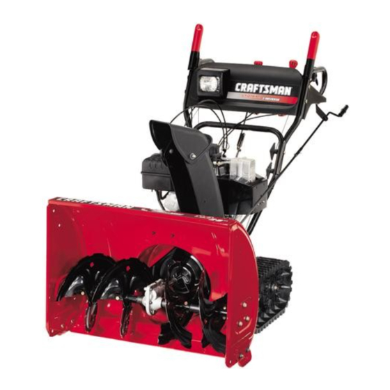
Owner's Manual
9 Horse Power
28" Two-Stage Track Drive
Snow Thrower
Model No.
247.88890
CAUTION: Before
using this product,
read this manual and
follow all safety rules
and operating
instructions.
Sears, Roebuck And Co., Hoffman Estates, IL 60179, U.S.A.
Visit our website: www.sears.com/craftsman
Printed in U.S.A.
•
Safety
•
Assembly
ES
•
Operation
•
Service
•
Maintenance
•
Español
. 770-10051F.fm
FORM NO
(5/2004)
Advertisement
Chapters
Table of Contents

Related Manuals for Craftsman 247.88890


Summary of Contents for Craftsman 247.88890
- Page 1 • Operation follow all safety rules • Service and operating • Maintenance instructions. • Español Sears, Roebuck And Co., Hoffman Estates, IL 60179, U.S.A. Visit our website: www.sears.com/craftsman . 770-10051F.fm FORM NO (5/2004) Printed in U.S.A.
-
Page 2: Table Of Contents
Sears will repair, free of charge, any defect in material and workmanship. If this Craftsman snow thrower is used for commercial or rental purposes, this warranty applies for only 30 days from the date of purchase. -
Page 3: Safe Operation Practices
IMPORTANT SAFE OPERATION PRACTICES WARNING: This symbol points out important safety instructions which, if not followed, could endanger the personal safety and/or property of yourself and others. Read and follow all instructions in this manual before attempting to operate this machine. Failure to comply with these instructions may result in personal injury. - Page 4 Never operate with a missing or damaged chute Before cleaning, repairing, or inspecting machine assembly. Keep all safety devices in place and working. disengage all control levers and stop the engine. Wait Never run an engine indoors or in a poorly ventilated until the auger/impeller come to a complete stop.
-
Page 5: Assembly
ASSEMBLY Unpacking 3. Remove handle knob A, washer and eyebolt attached to the left lower handle. Follow the 1. Remove screws/staples from top sides and ends of direction of arrows in Figure 2. Do not remove the the shipping crate. Set panel aside to avoid tire eyebolt from the chute directional control. - Page 6 Chute Clean-Out Tool 9. Secure the chute directional control to the bracket with flat washer and hairpin clip. See Figure 5. This tool, along with the electric cord, is fastened with a cable tie to the rear of the auger housing for shipping Spiral purposes.
- Page 7 5. Squeeze drive control against the handle and pull However, if you have to operate the snow thrower on the starter. The tracks should turn. gravel, keep the skid shoe in the highest position for 6. Now release the drive control and pull the starter maximum clearance between ground and shave plate.
-
Page 8: Operation
OPERATION Read this owner’s manual and safety rules before operating your snow thrower. Compare illustration below with your snow thrower to familiarize yourself with the location of various controls and adjustments. Operating Controls (See Figure 10 .) Drive Control/Auger Lock Shift Lever Chute Distance Control Headlight... - Page 9 Chute Distance Control Packed Snow: Locks the front end of the snow thrower down to the ground for hard-packed or icy snow The chute distance control lever on conditions. the handle panel adjusts the angle of the chute. Move this lever forward to Track Lock Lever decrease the distance and rearward...
- Page 10 CAUTION: Never use engine or carburetor cleaner 9. Plug the other end of the power cord into a three- products in the fuel tank. hole, grounded 120 volt A.C. receptacle. 10. Push primer button three times, • Fill the fuel tank outdoors and use a funnel or spout making sure to cover vent hole to prevent spilling.
- Page 11 7. Allow the engine to warm up for a few minutes 5. Wipe off all snow and moisture from the carburetor because the engine will not develop full power until area and around the engine. it reaches operating temperature. WARNING: The temperature of muffler and 8.
- Page 12 • If, however, you have to operate the snow thrower WARNING: Never use your hands to clean on gravel, keep the skid shoe in the highest position snow and ice from the discharge chute or for maximum clearance between the ground and auger housing.
-
Page 13: Maintenance
MAINTENANCE General Recommendations • Follow maintenance schedule below. • Periodically check all fasteners and make sure • Always observe safety rules when performing any these are tight. maintenance. WARNING: • The warranty on this snow thrower does not cover Before lubricating, repairing, or items that have been subjected to operator abuse inspecting, disengage all clutch levers and stop or negligence. - Page 14 Lubrication Grease Fittings Engine Refer to the separate engine manual packed with your unit for all engine lubrication instructions. Gear Shaft Lubricate the gear shaft with 6-n-1 grease at least once a season or after every 25 hours of operation (available at automotive stores).
-
Page 15: Service & Adjustment
SERVICE & ADJUSTMENTS the snow thrower housing. See Figure 16. WARNING: Always stop engine, disconnect 5. Reassemble the new shave plate with heads of spark plug wire and move it away from the carriage bolts to the inside of the housing. Tighten spark plug before performing any adjustments securely. - Page 16 Auger Belts Drive 6. Roll the front and rear auger belts off the engine Disc pulley. See Figure 19. Support Bracket Support Bracket Auger Pulley Drive Belt Idler Pulley Figure 21 Auger Belt Replacing Friction Wheel Rubber Figure 19 The rubber on the friction wheel is subject to wear and should be checked every 25 hours of operation;...
- Page 17 1. With the engine off, move the shift lever all the way Shift Rod forward to the highest speed. With the drive control Sprocket Assembly Spacer lever released, push the snow thrower forward. The unit should roll forward. Then engage the drive control grip.
- Page 18 If the answer was negative in steps 9 and 10, further 1. Remove the hairpin clip and slide the shift rod adjustment is necessary. connector up, to separate the upper shift rod from the lower shift rod. See Figure 27. 11.
-
Page 19: Off-Season Storage
OFF-SEASON STORAGE If your snow thrower is left unused for 30 days or longer, storage for 30 days or longer. it needs to be prepared for storage. Also, at the end of NOTE: Also experience indicates that alcohol blended the snow season, you should follow the same set of fuels (called gasohol or using ethanol or methanol) can instructions and store the snow thrower properly for the attract moisture which leads to separation and... -
Page 20: Troubleshooting
TROUBLESHOOTING Problem Cause Remedy Engine fails to start Fuel tank empty, or stale fuel. Fill tank with clean, fresh gasoline. Fuel becomes stale after thirty days. Blocked fuel line. Clean the fuel line. Choke not in the ON position Move switch to the ON position Faulty spark plug. - Page 21 SAFETY & DECORATIVE LABELS 777I22363 DRIVE AUGER LOCK 777D08420 ® 777I20324 6 FORW ARD 6 F O RW A R D 6 FORW ARD 2 REVERSE 2 REVERSE 2 R E V E R SE 777I22388 777I22386 777I22387 AUGER STARTING DRIVE CONTROL INSTRUCTIONS:...
-
Page 22: Parts List
PARTS LIST Craftsman Snowthrower Model 247.88890 Part of handle panel for reference only... - Page 23 Craftsman Snowthrower Model 247.88890 Ref. Ref. Part No. Part Description Part No. Part Description 684-0008A Shift Arm Assembly 712-0116 Jam Lock Nut 3/8-24 705-5204A Chute Directional Control 712-04063 Flange Lock Nut 710-0449 Carriage Screw 5/16-18 x 2.25 714-0104 Cotter Pin 710-0458 Carriage Bolt 5/16-18 x 1.75...
- Page 24 Craftsman Snowthrower Model 247.88890...
- Page 25 Craftsman Snowthrower Model 247.88890 Ref. Ref. Part No. Part Description Part No. Part Description 712-0116 Lock Jam Nut 3/8-24 790-00087 Bearing Housing 756-0178 Flat Idler 710-0726 Hex Screw 5/16-12 784-5632B Auger Idler Arm 725-0157 Cable Tie (not shown) 710-0459A Hex Cap Screw 3/8-24 x 1.50...
- Page 26 Craftsman Snowthrower Model 247.88890 Supplied on engine...
- Page 27 Craftsman Snowthrower Model 247.88890 Ref. Part No. Part Description 710-1652 Hex Washer Screw 1/4-20 x.625 731-1324 Belt Cover 732-0710 Extension Spring 710-0627 Hex Screw 5/16-24 x.75 710-3005 Hex Cap Screw 3/8-16 x 1.25 05896A Drive Clutch Idler Bracket 748-0234 Shoulder Spacer...
- Page 28 Craftsman Snowthrower Model 247.88890 32 32 30 31 NOTE: For painted parts, please refer to the list of color codes below. Please add the applicable color code, wherever needed, to the part number to order a replacement part. For instance, if a part, numbered 700-xxxx, is painted red, the part number to order would be 700-xxxx-0721.
- Page 29 Craftsman Snowthrower Model 247.88890 Ref. Ref. Part No. Part Description Part No. Part Description 736-0270 Bell Washer.265 ID x.75 OD 784-5648 Frame Cover 736-0176 Flat Washer 1/4 ID x.93 OD 710-0896 AB Screw 1/4-14 x.625 741-1111 Hex Flange Bearing 748-0190...
- Page 30 Craftsman Snowthrower Model 247.88890...
- Page 31 Craftsman Snowthrower Model 247.88890 Ref. Ref. Part No. Part Description Part No. Part Description 720-0223 Grip 713-0233 Chain 710-0604A Tap Screw, 5/16-18 x.625 618-0169A Track/Steering Shaft Assembly 784-5642 Track Lockout Plate 683-0024 Track Hub Assembly 710-0157 Hex Cap Screw, 5/16-24 x.75...
- Page 32 Tecumseh Engine HMSK90-156569G For Craftsman Snow Thrower Model 247.88890...
- Page 33 Tecumseh Engine HMSK90-156569G For Craftsman Snow Thrower Model 247.88890 Key No. Part No. Description Key No. Part No. Description 650880 Lock Washer 35385 Cylinder 650881 Flywheel Nut 27652 Dowel Pin 100. 35135A Solid State Ignition (Incl. 101) 650820 Screw, 1/4-20 x 0.5”...
- Page 34 Tecumseh Engine HMSK90-156569G For Craftsman Snow Thrower Model 247.88890 Key No. Part No. Description Key No. Part No. Description 260. 35447A Blower Housing 329. 610973 Terminal 261. 650788 Screw, 5/16-18 x 3/4" 335. 36547 Carburetor Cover 262. 651084 Screw, 5/16-18 x 9/16"...
- Page 35 Tecumseh Engine HMSK90-156569G For Craftsman Snow Thrower Model 247.88890 Key No. Part No. Description 640052 Carburetor 631776A Throttle Shaft & Lever Assembly 631970 Throttle Return Spring 631778 Throttle Shutter 650506 Shutter Screw 632112 Choke Shaft & Lever Assembly 632174 Choke Shutter...
- Page 36 Tecumseh Engine HMSK90-156569G For Craftsman Snow Thrower Model 247.88890 Key No. Part No. Description 590749 Rewind Starter 590599A Spring Pin (Incl. 4) 590600 Washer 590679 Retainer 590601 Washer 590678 Brake Spring 590680 Starter Dog 590412 Dog Spring 590682 Pulley & Rewind Spring Assembly...
- Page 37 Tecumseh Engine HMSK90-156569G For Craftsman Snow Thrower Model 247.88890 33329E Electric Starter 110 Volt (optional) 33451 Dust Cover 33842 Retainer Ring 33430 Spring Retainer 33431 Anti-Drift Spring 37050 Gear & Nut (Incl. 2) 35449 Drive End Cap Assembly 35450 "O" Ring...
-
Page 38: Espanòl
Sears reparará sin cargo cualquier defecto de materiales o mano de obra. Si esta máquina quitanieve Craftsman se utiliza para propósitos comerciales o de alquiler, esta garantía se aplica sólo durante 30 días a partir de la fecha de compra. -
Page 39: Prácticas De Seguridad En La Operación
MEDIDAS IMPORTANTES DE SEGURIDAD ADVERTENCIA: Este símbolo indica instrucciones de seguridad importantes que de no seguirse, se podría poner en peligro la seguridad personal y/o la propiedad suya y de terceros. Lea y siga todas las instrucciones en este manual antes de iniciar la operación de esta máquina. - Page 40 Sea sumamente precavido cuando opere la máquina sobre una Antes de realizar la limpieza, reparar o revisar la máquina, superficie con grava o cuando la cruce. Manténgase alerta por desengrane todas las palancas de control y detenga el motor. si se presentan peligros ocultos o tránsito. Espere a que la barrena / motor se detenga por completo.
- Page 41 ENSAMBLADO Desempaque Retire los tornillos / grapas de los lados y extremos superiores Control de la caja de embalaje. Retire el panel para evitar que se direccional pinchen las llantas o que se produzcan lesiones personales. Retire y descarte la bolsa de plástico que cubre la unidad. del canal Retire cualquier parte suelta que se incluya con la unidad (por ejemplo, el manual del operador, el manual del motor, etc.).
-
Page 42: Montaje
Perilla de manija B Arandela curva Perno de ojo Conector Perilla de manija A Varilla de cambio Figura 4 inferior Inserte el perno de carro a través del orificio inferior de las Figura 6 manijas superior e inferior en el lado derecho, y asegúrelo con NOTA: Si el conector no está... - Page 43 embrague debería estar flojo. Ajuste la contratuerca para asegurar el cable una vez alcanzado el ajuste correcto. Empuñadura del embrague. NOTA: los cables están mal ajustados si las barrenas Contra siguen girando cuando se suelta el embrague de las tuerca mismas, o si la máquina sigue en funcionamiento cuando se suelta el embrague de la transmisión.
-
Page 44: Operacion
OPERACIÓN Lea este manual del propietario y las reglas de seguridad antes de poner en funcionamiento su máquina quitanieve. Compare las ilustraciones que aparecen debajo con su unidad para familiarizarse con la ubicación de los distintos controles y ajustes. Controles de operación (Vea la Figura 10 ) Traba del control de transmisión / Barrena Palanca de cambios... - Page 45 Control de distancia del Nieve muy compactada: bloquea la parte frontal de la máquina quitanieve pegada al suelo para condiciones de canal nieve muy compactada o congelada. La palanca de control de distancia del Palanca de traba canal, situada en el panel de la manija, de orugas ajusta el ángulo del canal.
- Page 46 combustible si se dejan en el depósito durante el encendido dentro de la ranura. No gire la llave. Guarde la segunda llave en un lugar seguro. almacenamiento. Rote la perilla de obturación a posición FULL (máximo). PRECAUCIÓN: Nunca use productos de limpieza para el Mueva el control del estrangulador a la posición FAST (rápido).
- Page 47 posición OFF. Si el motor falla, gire hacia posición FULL, luego estrangulador hasta la posición OFF (apagado) y saque la mueva lentamente hacia posición OFF. llave. No gire la llave. Deje que el motor se enfríe por algunos minutos ya que el Limpie toda la nieve y la humedad del área del carburador y motor no alcanzará...
- Page 48 PRECAUCIÓN: No se recomienda operar esta parte posterior de la caja de la barrena. Vea la Figura 12. Use el extremo con forma de pala de la herramienta para destapar y máquina quitanieve sobre grava. recoger la nieve y el hielo acumulados alrededor del canal de •...
-
Page 49: Mantenimiento
MANTENIMIENTO Recomendaciones generales las temporadas. • Siga el cronograma de mantenimiento que se • Respete siempre las reglas de seguridad cuando presenta a continuación. realice tareas de mantenimiento. • Revise periódicamente todos los sujetadores y • La garantía de esta máquina quitanieve no cubre compruebe que estén bien ajustados. - Page 50 Con el motor ubicado en suelo parejo, el aceite debe estar en la lubricante. Vea la Figura 15. marca FULL (lleno) de la varilla del nivel de aceite. Vea la Es posible encontrar accesorios de engrasado en cada Figura 13 . extremo del eje de la barrena.
-
Page 51: Servicio Y Ajuste
SERVICIO Y AJUSTES tuercas hexagonales que ajustan dicha placa a la caja de la ADVERTENCIA: máquina quitanieve. Vea la Figura 16. Detenga siempre el motor, Vuelva a ensamblar la placa de raspado nueva con las cabezas desconecte el cable de la bujía y póngalo separado de de los pernos de carro en el lado interior de la caja. - Page 52 Correas de las barrenas Disco de Saque las correas de las barrenas frontal y trasera de la polea transmisión del motor. Vea la Figura 19. Ménsula de soporte Ménsula de soporte Polea de la barrena Correa loca Correa transmisión Figura 21 Correa de la barrena Reemplazo de la goma de la rueda de...
- Page 53 control de transmisión, empuje la máquina quitanieve hacia Montaje delante. La unidad debería avanzar. Luego engrane la Rueda dentada la varilla de empuñadura del control de transmisión. Las ruedas deberían Separador dejar de girar. cambio Suelte la empuñadura de control de transmisión y empuje nuevamente la unidad.
- Page 54 10. Habiendo engranado el control de transmisión, controle si la Retire el broche de horquilla y deslice el conector de la varilla de cambio hacia arriba, para separar la varilla de cambio rueda de fricción hace contacto con la placa de transmisión. superior de la inferior.
-
Page 55: Almacenamiento Fuera De Temporada
ALMACENAMIENTO FUERA DE TEMPORADA Si su máquina quitanieve no se va a utilizar durante 30 ecendido. Para evitar estos problemas, el sistema del días o más, tiene que prepararla para el combustibledebe ser vaciadoantes de almacenar la almacenamiento. Asimismo, al final de la temporada de máquina durante 30 días o más. -
Page 56: Solución De Problemas
GUÍA PARA LA SOLUCIÓN DE PROBLEMAS Problema Causa Remedio El motor no arranca El depósito de combustible está vacío o el Llene el tanque con gasolina limpia y fresca. El combustible es viejo. combustible envejece transcurridos treinta días. La línea del combustible está bloqueada. Limpie la línea del combustible. - Page 57 YOUR NOTES...
- Page 58 YOUR NOTES...
- Page 59 YOUR NOTES...
- Page 60 Get it fixed, at your home or ours! Your Home For repair – in your home – of all major brand appliances, lawn and garden equipment, or heating and cooling systems, no matter who made it, no matter who sold it! For the replacement parts, accessories and owner’s manuals that you need to do-it-yourself.
Need help?
Do you have a question about the 247.88890 and is the answer not in the manual?
Questions and answers