Advertisement
Quick Links
Description
Demonstration circuit DC1743A features the LTM
an EN55022 class B certified, high input and output voltage,
high efficiency, switch mode step-down power µModule
regulator. The input voltage range is from 5V to 36V. The
output voltage is jumper programmable from 3.3V to 12V
with a rated load current of 8A. Derating is necessary
for certain V
, V
IN
OUT
please refer to LTM4613 data sheet for derating curves.
Only input and output capacitors are needed externally.
The DC1743A offers the TRACK/SS pin allowing the user
to program output tracking or soft-start period. Output
perForMAnce sUMMArY
PARAMETER
Input Voltage Range
Output Voltage V
OUT
Maximum Continuous Output Current
Default Operating Frequency
Efficiency
Load Transient
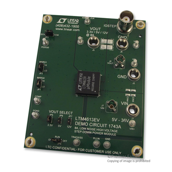
BoArD photo
Arrow.com.
Downloaded from
, frequency and thermal conditions:
(T
CONDITIONS
Jumper Selectable
Derating Is Necessary for Certain Operating Conditions. See Data Sheet
for Details.
V
= 12V
OUT
V
= 5V
OUT
V
= 3.3V
OUT
V
= 12V, V
IN
V
= 12V, V
IN
DEMO MANUAL DC1743A
8A, High Voltage Power
4613EV,
voltage margining can also be realized through jumper
®
position selections.
®
Higher efficiency at low load currents is achieved by setting
the MODE pin jumper to DCM. The PLL pin is available
to synchronize the LTM4613EV to an external clock. The
LTM4613 data sheet must be read in conjunction with
this demo manual prior to working on or modifying demo
circuit DC1743A.
Design files for this circuit board are available at
http://www.linear.com/demo
L, LT, LTC, LTM, µModule, Linear Technology and the Linear logo are registered trademarks of
Linear Technology Corporation. All other trademarks are the property of their respective owners.
= 25°C)
A
= 5V, I
= 8A
OUT
OUT
= 5V
OUT
LTM4613
µModule Regulator
VALUE
5V to 36V
3.3V, 5V, 12V; ± 2%
8A
DC
600kHz
250kHz
165kHz
93.0% See Figure 3
See Figure 4
dc1743af
1
Advertisement

Related Manuals for Linear Technology DC1743A


Summary of Contents for Linear Technology DC1743A
- Page 1 The DC1743A offers the TRACK/SS pin allowing the user http://www.linear.com/demo to program output tracking or soft-start period. Output L, LT, LTC, LTM, µModule, Linear Technology and the Linear logo are registered trademarks of Linear Technology Corporation. All other trademarks are the property of their respective owners. perForMAnce sUMMArY = 25°C)
-
Page 2: Quick Start Procedure
DEMO MANUAL DC1743A qUick stArt proceDUre Demonstration circuit DC1743A is an easy way to evalu- 4. Vary the input voltage from 5V to 36V and adjust the ate the performance of the LTM4613EV. Please refer to load current from 0A to 8A. Observe the output voltage... - Page 3 DEMO MANUAL DC1743A qUick stArt proceDUre – LOAD – – – – DC1743A F01 Figure 1. Proper Measurement Equipment Setup dc1743af Arrow.com. Arrow.com. Arrow.com. Downloaded from Downloaded from Downloaded from...
- Page 4 = 5V = 12V = 12V LOAD CURRENT (A) LOAD CURRENT (A) LOAD CURRENT (A) DC1743A F03a DC1743A F03b DC1743A F03c Figure 3. Measured DC1743A Efficiency at Different V and V (DCM Mode Enabled) dc1743af Arrow.com. Arrow.com. Arrow.com. Arrow.com. Downloaded from...
- Page 5 DEMO MANUAL DC1743A qUick stArt proceDUre OUT_STEP OUT_STEP 5A/DIV 5A/DIV 100mV/DIV 200mV/DIV 100µs/DIV 100µs/DIV DC1743A F04a DC1743A F04b = 12V, V = 5V = 24V, V = 12V 0A TO 4A LOAD STEP 0A TO 4A LOAD STEP = 1x47µF/16V/POSCAP+3x47µF/16V/X5R+1x10µF/16V/X5R = 1x47µF/16V/POSCAP+3x47µF/16V/X5R+1x10µF/16V/X5R...
-
Page 6: Parts List
DEMO MANUAL DC1743A pArts list ITEM REFERENCE PART DESCRIPTION MANUFACTURER/PART NUMBER Required Circuit Components CAP, NPO 47pF 50V 10% 0603 AVX 06035A470KAT1A CIN1 CAP, ALUM 100µF 50V 10% SUNCON 50CE100FS CIN2, CIN3, C8, C9, C10 CAP, X5R 10µF 50V 20% 1210... -
Page 7: Schematic Diagram
Information furnished by Linear Technology Corporation is believed to be accurate and reliable. However, no responsibility is assumed for its use. Linear Technology Corporation makes no representa- tion that the interconnection of its circuits as described herein will not infringe on existing patent rights. - Page 8 Linear Technology Corporation (LTC) provides the enclosed product(s) under the following AS IS conditions: This demonstration board (DEMO BOARD) kit being sold or provided by Linear Technology is intended for use for ENGINEERING DEVELOPMENT OR EVALUATION PURPOSES ONLY and is not provided by LTC for commercial use. As such, the DEMO BOARD herein may not be complete in terms of required design-, marketing-, and/or manufacturing-related protective considerations, including but not limited to product safety measures typically found in finished commercial goods.
Need help?
Do you have a question about the DC1743A and is the answer not in the manual?
Questions and answers