Advertisement
DESCRIPTION
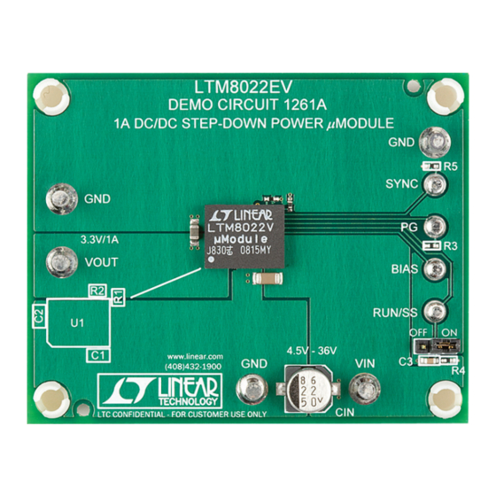
Demonstration circuit 1261A features the LTM
down μModule
regulator delivering a 3.3V output from a
®
4.5V to 36V input supply. As a step-down converter, the
LTM8022 requires a minimum amount of headroom to keep
the output in regulation. The device may be synchronized
to an external clock or allowed to enter low ripple Burst
Mode
®
operation at light load conditions by applying the
appropriate signal to the SYNC pin. Current sharing with
another LTM8022 is enabled by tying the VIN, VOUT and
SHARE pins together to support higher output loads.
PERFORMANCE SUMMARY
PARAMETER
Input Voltage Range
Output Voltage, V
OUT
Maximum Output Current
Typical Switching Frequency
BOARD PHOTO
Downloaded from
Elcodis.com
electronic components distributor
DEMO MANUAL DC1261A
®
8022 step-
The LTM8022 data sheet must be read in conjunction with
demo manual prior to working on or modifying demo
circuit DC1261A.
Design files for this circuit board are available at
http://www.linear.com/demo
L, LT, LTC, LTM, μModule, Burst Mode, Linear Technology and the Linear logo are registered
trademarks of Linear Technology Corporation. All other trademarks are the property of their
respective owners.
(T
= 25°C)
A
CONDITION
LTM8022
36V, 1A Step-Down
µModule Regulator
VALUE
4.5V to 36V
3.3V ±3%
1A
600kHz
dc1261af
1
Advertisement
Table of Contents

Related Manuals for Linear Technology DC1261A


Summary of Contents for Linear Technology DC1261A
- Page 1 The device may be synchronized http://www.linear.com/demo to an external clock or allowed to enter low ripple Burst L, LT, LTC, LTM, μModule, Burst Mode, Linear Technology and the Linear logo are registered Mode ® operation at light load conditions by applying the trademarks of Linear Technology Corporation.
- Page 2 DEMO MANUAL DC1261A QUICK START PROCEDURE Demonstration circuit 1261A is an easy way to evaluate 3. Turn on the input power supply. the performance of the LTM8022. Refer to Figure 1 for Note: Make sure that the input voltage does not exceed proper measurement equipment setup and follow the the maximum input voltage.
- Page 3 DEMO MANUAL DC1261A QUICK START PROCEDURE – – LOAD – – – – Figure 1. Proper Measurement Equipment Setup Figure 2. Measuring Input or Output Ripple dc1261af Downloaded from Elcodis.com electronic components distributor...
- Page 4 DEMO MANUAL DC1261A PARTS LIST ITEM REFERENCE DESCRIPTION MANUFACTURER/PART NUMBER Required Circuit Components CAP , 1206 2.2μF 10% 50V X7R MURATA GCM31CR71H225KA55L CAP , 0805 22μF 10% 6.3V X5R TAIYO YUDEN JMK212BJ226KG-T RES, 0402 154k 1% 1/16W VISHAY CRCW0402154KFKEA RES, 0402 56.2k 1% 1/16W...
- Page 5 Information furnished by Linear Technology Corporation is believed to be accurate and reliable. However, no responsibility is assumed for its use. Linear Technology Corporation makes no representa- tion that the interconnection of its circuits as described herein will not infringe on existing patent rights.
- Page 6 Linear Technology Corporation (LTC) provides the enclosed product(s) under the following AS IS conditions: This demonstration board (DEMO BOARD) kit being sold or provided by Linear Technology is intended for use for ENGINEERING DEVELOPMENT OR EVALUATION PURPOSES ONLY and is not provided by LTC for commercial use. As such, the DEMO BOARD herein may not be complete in terms of required design-, marketing-, and/or manufacturing-related protective considerations, including but not limited to product safety measures typically found in finished commercial goods.
Need help?
Do you have a question about the DC1261A and is the answer not in the manual?
Questions and answers