Advertisement
Quick Links
DESCRIPTIO
This demonstration board implements the IrDA
dards for infrared data communications. It is a complete
transmitter/receiver for use in SIR, FIR and 4PPM infrared
data links. The LT
supports IrDA data rates up to 4Mbps, as well as other
modulation methods such as Sharp-ASK and TV remote
control. This board can be configured for IrDA-SIR (Infra-
red Data Association Serial Infrared), IrDA-FIR (Infrared
Data Association Fast Infrared) and 4PPM (4MHz pulse-
position modulation).
The LT1328, in the SO-8 and MSOP packages, contains
all the necessary circuitry to convert current pulses from
an external photodiode to a digital TTL output, while
rejecting unwanted lower frequency interference. The
LT1328 requires only six external components to make
an IrDA compatible receiver. Figure 1 is a block diagram
of the LT1328. The preamp converts the photodiode
current into a voltage that trips the comparator. The
internal servo action suppresses only frequencies below
the R
/C
pole. This highpass filtering attenuates
gm
FILT
interfering signals, such as sunlight or incandescent and
fluorescent lamps, and is selectable at Pin 7 for low or
high data rates. The upper frequency limit for the servo
is set by an external capacitor C4. The pole is found by the
formula f(Hz) = 25[1/(2π • 60k • C4)]; a 330pF capacitor
for C4 will pass signals above 200kHz (FIR and 4PPM).
To lower the passband for SIR, move the jumper on the
demo board from FIR, 4PPM to SIR. This takes the MODE
pin (Pin 7) from ground to V
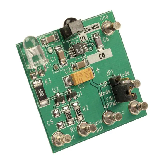
BOARD PHOTO
Arrow.com.
Downloaded from
U
®
1328 is a photodiode receiver that
, which switches C1 (on
CC
DEMO MANUAL DC112A
DEMO MANUAL DC112A
®
stan-
Pin 3) in parallel with C4. The required filtering for V
(Pin 8) is provided by C6, a 1000pF cap to ground. The
DATA pin (Pin 5) is the output of the comparator. The
quiescent, no signal state is a TTL HIGH; a TTL LOW
occurs when the photodiode receives light. Power re-
quirements for the LT1328 are minimal: a single 5V
supply and 2mA of quiescent current. The LT1328's ease
of use and flexibility make it an ideal solution for numer-
ous other photodiode receiver applications. The LT1328
is available in the 8-pin SO and the tiny MSOP package for
size-critical applications.
An IrDA transmitter is also provided on the demo board.
Figure 2 shows the LED driver circuit and the LT1328
receiver. The LED transmits light when the transmit input
pin on the demo board is high (5V), and is off when the
Transmit Input is low (0V). The receiver output is the DATA
pin on the demo board (which is Pin 5 on the LT1328). The
Data pin is high for no received light and a TTL LOW for a
light pulse. To switch from SIR to the faster data rates, a
jumper is provided. Remote switching can be accom-
plished by removing the jumper and accessing the MODE
pin: TTL HIGH for SIR and TTL LOW for faster data rates.
Actual transmit and receive waveforms can be seen in
Figures 3, 4 and 5 for SIR, FIR and 4PPM, respectively.
The lower waveform in each photo is the transmit input
to the demo board. The upper waveform is the demo
board DATA pin (Pin 5 of the LT1328).
, LTC and LT are registered trademarks of Linear Technology Corporation.
IrDA is a registered trademark of the Infrared Data Association.
LT1328 IrDA Infrared
Receiver
BIAS
1
Advertisement

Related Manuals for Linear Technology DC112A


Summary of Contents for Linear Technology DC112A
- Page 1 DATA pin (Pin 5 of the LT1328). demo board from FIR, 4PPM to SIR. This takes the MODE , LTC and LT are registered trademarks of Linear Technology Corporation. pin (Pin 7) from ground to V , which switches C1 (on IrDA is a registered trademark of the Infrared Data Association.
- Page 2 DEMO MANUAL DC112A PACKAGE AND SCHEMATIC DIAGRAMS 1.5V BIAS 1000pF PREAMP BIAS PHOTODIODE TEMIC BPV22NF MODE HIGH: SIR LOW: FIR AND 4PPM FILTER DC SERVO FILTER – 330pF 10nF FILTER SWITCH 0.1µF 10µF – DATA COMP DC112A BD Figure 1. LT1328 Block Diagram...
-
Page 3: Parts List
LT1328 demo board is to have a separate LED trans- pin (both ground pins are common). mitter, like that on DC112A, that can be placed a measured Set the transmitter close to the receiver (≈1cm), input an distance from the receiver. If a second board is not... - Page 4 DEMO MANUAL DC112A OPERATIO IrDA-SIR Because SIR systems transmit a pulse for a zero and is shown on the top. Note that the receiver output is a TTL nothing for a one (see Figure 3a), the two photographs LOW for a transmitted light pulse. The two photos, Figures demonstrating the SIR modulation show a sequence of 3b and 3c, show received data at 1 meter and 1cm.
- Page 5 DEMO MANUAL DC112A OPERATIO IrDA-FIR With the exception of data rate and pulse width, FIR is very range of 1 meter. The second photo, Figure 4c, shows the similar to SIR (see Figure 4a). The same precautions about receiver 1cm from the transmitter. Again, a detected light pulse will make the receiver switch to a TTL LOW state.
- Page 6 DEMO MANUAL DC112A OPERATIO IrDA-4PPM 4Mbps pulse position modulation positions one pulse, to the transmitter, the LT1328’s output can be evaluated. 125ns wide in one of four data windows for every data bit The first photo, Figure 5b, is when the receiver is 1 meter pair.
- Page 7 Information furnished by Linear Technology Corporation is believed to be accurate and reliable. However, no responsibility is assumed for its use. Linear Technology Corporation makes no represen- tation that the interconnection of its circuits as described herein will not infringe on existing patent rights.
- Page 8 0.037 0.015 TOTAL HOLES dc112af LT/GP 0197 500 • PRINTED IN USA Linear Technology Corporation 1630 McCarthy Blvd., Milpitas, CA 95035-7417 (408) 432-1900 FAX: (408) 434-0507 TELEX: 499-3977 www.linear-tech.com © LINEAR TECHNOLOGY CORPORATION 1997 Arrow.com. Arrow.com. Arrow.com. Arrow.com. Arrow.com. Arrow.com.
Need help?
Do you have a question about the DC112A and is the answer not in the manual?
Questions and answers