Advertisement
Available languages
Available languages
Quick Links
Advertisement

Related Manuals for Craftsman 351.214191


Summary of Contents for Craftsman 351.214191
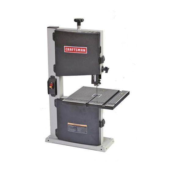
- Page 1 perator's nual ® BENCH TOP BAND SAW Model No. 351.214191 CAUTION: Read and follow all Safety Rules and Operating instructions before First Use of this Product. Sears Brands Management Corporation, Hoffman Estates, IL 60179 U.S.A. www.sears.comlcraftsman 31829.00 Draft (12/23/09)
- Page 2 PROFESSIONAL TOOL Do not use power tools in damp or wet locations. Do If this Craftsman tool fails due to a defect in material or not expose power tools to rain. workmanship within one year from the date of purchase, •...
-
Page 3: Power Source
• Avoid accidental start-up. Make sure that the tool is WARNING: Never use highly volatile solvents. Non in the OFF position before plugging in. flammable solvents are recommended to avoid possible fire hazard. • Do not force tool. It will work most efficiently at the rate for which it was designed. -
Page 4: Grounding Instructions
Refer to Figures 4 - 7, pages 5 and 6. cord or plug is necessary, do not connect the green (or The Craftsman 9" Bench Top Band Saw features weld- green and yellow) wire to a live terminal. ed steel frame construction and a solid cast iron table Where a 2-prong wall receptacle is encountered, surface to insure durability. -
Page 5: Specifications
SPECIFICATIONS Depth of throat at 90 ° ......9" Maximum depth of cut at 90 ° ....3%" Maximum depth of cut at 45 ° ....2" Table size ......113/4x 113/4" Table tilt ......0 ° to 45 ° Wheel diameter ...... -
Page 6: Installing Blade
• Lower the upper blade guide completely and unsnap • Disconnect band saw from power source. guide panel to access the blade (see Figure 6). • To check the blade tracking, rotate drive wheel by hand in clockwise direction. View blade through tracking window. - Page 7 • Adjust ball bearing at rear of blade by loosening Lock adjustment by tightening screws. socket head bolt and repositioning shaft BLADE SELECTION (see Figure 8). • Blades vary depending on type of material, size of workpiece and type of cut that is being performed. Characteristics which make blades different are width, thickness and pitch.
- Page 8 the portion of table which is to right of blade and before cut. Cut small corners by sawing around them. Saw to WARNING: Make certain that unit is disconnected remove scrap until desired shape is obtained. from power source before attempting to service or BEVEL CUTTING remove any component.
- Page 9 PTO M CORRECTIVE ACTION POSSIBLE CAUSE(S) 1. Material not secure on table Excessive blade breakage •Squarely place work on table 2. Blade too coarse for material Use finer pitch blade 3. Teeth in contact with work before Place blade in contact with work after saw is sawing started and has reached full speed 4.
- Page 10 iVlodel 351.21 4191 Figure 10 - Replacement Parts illustration for Frame, Table and Guides 2 38...
- Page 11 PART NO, DESCRIPTION QTY. PART NO. DESCRIPTION QTY. 31830.00 Table Insert 31839.00 Lower Guide Block 31831.00 Table 31840.00 Lower Bearing Bracket 31832.00 STD315488 Miter Gauge Assembly 606ZZ Ball Bearing* 31833.00 25083.00 Table Locking Insert Bearing Stud STD852006 6mm Lock Washer* 31841.00 Screw STD844610...
- Page 12 Model 351.21 4191 Figure 11 - Replacement Parts illustration for Drive...
- Page 13 PART NO. DESCRIPTION QTY. PART NO. DESCRIPTION QTY. STD863510 5-0.8 x lOmm Pan Head STD852010 lOmm Lock Washer* Screw* 31852.00 Idler Wheel 01474.00 5mm Serrated Washer 31853.00 Wheel Band STD870825 8-1.25 x 25mm Socket Head 00221.00 3AMI-IO Retaining Ring Bolt* STD833020 6-1.0 x 20mm Hex Head Bolt* 4 STD851008...
- Page 14 Est_ alerta y piense claramente. Nunca opere herramientas Siesta herramienta Craftsman fallara por causa de defectos mec_nicas cuando est6 cansado, intoxicado o bajo la en el material o en la mano de obra en un lapso de un aSo a influencia de medicaci6n que produzca somnolencia.
- Page 15 • Mantenga la herramienta lubricada y limpia de modo que funcione de la manera m_.s segura. Retire las herramientas de ajuste. Desarrolle el habito Verifique que no hayan ocurrido daSos durante el envio. Si de verificar que hayan sido retiradas las herramientas hay daSos, se debera presentar un reclamo a la compaSia de ajuste antes de encender la m_.quina.
- Page 16 INSTALE LA MESA Consulte la Figura 10. tierra adecuadamente Tomacorriente_puestoa • Remueva el conjunto de la manilla (Clave No. 18) del a tierra Punta de conexi6n -,4_,, %,_..9._ l bastidor de la sierra. Enchufe de 3 puntas Coloque el conjunto de la mesa sobre el bastidor de la sierra.
- Page 17 Consulte las Figuras 4-17 en las pAginas 17-19. posici6n ON (encendido) sin la Ilave. La sierra de banda de 9" Craftsman cuenta con un bastidor AVlSO: Si se extrae la Ilave con el interruptor en la posici6n de acero y una s61ida superficie de mesa de hierro fundido...
- Page 18 Deslice la hoja nueva en la ranura de la mesa y sobre las Manilla de tensi6n ruedas superior y inferior de la hoja. Deslice la hoja entre sus protecciones. Palanca de ten- Tense la hoja girando la palanca de tensi6n de la hoja en el si6n de la hoja senfido de las manecillas del reloj, hasta que tope (vea la Figura 5).
- Page 19 Rodamiento Pasador de guia Figura 9 - Guias Inferiores de la Hoja Afloje los pernos de cabeza hueca (vea la Figura 10, Clave No. 61) y ajuste la posici6n del puntal de la guia Figura 7 - Guias Superiores de la Hoja inferior de manera que la parte posterior de la hoja quede ubicada a una distancia de 0.002 pulg.
- Page 20 • Cuando se corten materiales m_.s duros, en cuyo caso el ADVERTENCIA: No use nunca simultaneamente la guia de golpe es mAs nocivo, se recomienda una hoja de 8 a 12 ingletes y el reborde para serrar a Io largo. La hoja se puede atascar en la pieza de trabajo.
- Page 21 SINTOMA MEDIDA CORRECTIVA CAUSAS(S) POSIBLE(S) 1. Cuadre el material sobre la mesa Las hojas se rompen 1. El material no est,. seguro en la mesa excesivamente 2. Los dientes son demasiado gruesos 2. Use una hoja de paso mAs fino para el material 3.
- Page 22 Registro de Servicios Sierra de Banda de Banco de 9" Craftsman i FECHA IVIANTENllVIIENTO EFECTUADO PARTES DE REPUESTO NECESARIAS...
- Page 23 NOTAS...
- Page 24 Your Home For expert troubleshooting and home solutions advice: www.managemyhome.com For repair - in your home - of all major brand appliances, lawn and garden equipment, or heating and cooling systems, no matter who made it, no matter who sold it! For the replacement parts, accessories owner's manuals that you need to do-it-yourself.
Need help?
Do you have a question about the 351.214191 and is the answer not in the manual?
Questions and answers