Table of Contents
Advertisement
Available languages
Available languages
Quick Links
Operator's Manual
®
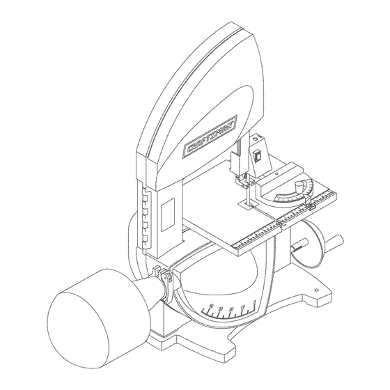
10"
TILTING HEAD BENCH TOP
BAND SAW WITH DUST COLLECTION
Model No.
351.214610
\
\
\
\
\
CAUTION:
Read and follow
all Safety Rules and Operating
Instructions
before First Use
of this Product.
Sears, Roebuck and Co., Hoffman Estates, IL 60179 U.S.A.
www.sears.com/craftsman
23563.00 Draft (03/18/05)
Advertisement
Table of Contents

Related Manuals for Craftsman 351.214610


Summary of Contents for Craftsman 351.214610
- Page 1 TILTING HEAD BENCH TOP BAND SAW WITH DUST COLLECTION Model No. 351.214610 CAUTION: Read and follow all Safety Rules and Operating Instructions before First Use of this Product. Sears, Roebuck and Co., Hoffman Estates, IL 60179 U.S.A. www.sears.com/craftsman 23563.00 Draft (03/18/05)
- Page 2 • Be alert and think clearly. Never operate power tools when tired, intoxicated or when taking medications that cause drowsiness. Warranty ........Safety Rules....... PREPARE WORK AREA FOR JOB Unpacking ........• Keep work area clean. Cluttered work areas invite Assembly .
- Page 3 • Never stand on tool. Serious injury could occur if tool IMPORTANT: Table is coated with a protectant. To is tipped or if blade is unintentionally contacted. ensure proper fit and operation, remove coating. Coating is easily removed with mild solvents, such as •...
-
Page 4: Power Source
Plug must be plugged into matching outlet that is prop- erly installed and grounded in accordance with all local codes and ordinances. Do not modify plug provided. If it Referto Figures 2 and3. will not fit in outlet, have proper outlet installed by a qualified electrician. -
Page 5: Specifications
Refer to Figures 4 - 13, pages 5-8. clockwise all the way until it locks in position to The Craftsman 10" Tilting Head Band Saw features alu- release blade tension (see Figure 4). minum frame construction and a solid cast iron table surface to insure durability. -
Page 6: Upper Blade Guides
TRACKING BLADE WARNING: Be very careful; improperly tracked blade may spring out from wheels causing serious injury. Do not perform tracking adjustment while band saw is running. • Disconnect band saw from power source. • To check the blade tracking, rotate drive wheel by hand in clockwise direction. -
Page 7: Lower Blade Guides
• Adjust ball bearing at rear of blade by loosening hex nut and turning bearing shaft (see Figure 8). Ball Hex Nut Bearing Shaft Figure 10 - Lower Blade Guides • Loosen socket head bolts (see Figure 11 ) and adjust lower guide bracket position so that rear of blade is positioned inside the groove of roller (see Figure 10). - Page 8 BLADE WIDTH BEVEL CUTTING • Width of blade describes distance from tip of a tooth Refer to Figure 10. to back of blade. • Perform bevel cutting by tilting head to desired • Width of blade affects rigidity of blade. A wider blade degree.
- Page 9 WARNING: Make certain that unit is disconnected from power source before attempting to service or remove any component. CLEANING • Keep machine and workshop clean. Do not allow sawdust to accumulate on band saw. • Keep wheels clean. Debris on wheels will cause poor tracking and blade slippage.
- Page 10 Service Record Craftsman 10" Tilting Head Bench Top Band Saw with Dust Collection DATE MAINTENANCE PERFORMED REPLACEMENT PARTS REQUIRED...
- Page 11 CORRECTIVE ACTION SYMPTOM POSSIBLE CAUSE(S) 1. Material not secure on table Excessive blade breakage 1. Squarely place work on table 2. Blade too coarse for material 2. Use finer pitch blade 3. Teeth in contact with work before 3. Place blade in contact with work after saw is sawing started and has reached full speed 4.
- Page 12 Model 351.214610 Figure 14 - Replacement Parts Illustration for Frame...
- Page 13 PART NO. PART NO. DESC RIPTION QTY. DESC RIPTION QTY. 20803.01 Front Door 20822.00 Upper Guide Seat 16080.00 20823.00 Switch with Key Spring 23742.00 Tube 20824.00 Locking Insert 23741.00 Switch Plate 20825.00 Upper Guide Bracket STD870512 5-0.8 x 12mm Socket 20826.00 Blade Guard with Head Bolt*...
- Page 14 Model 351.214610 Figure 15 - Replacement Parts Illustration for Base 33 32 ®...
- Page 15 PART NO. DESCRIPTION QTY. 20843.00 Head Mounting Bracket 20844.00 Base 20845.00 Pointer Assembly (incl. Key No. 30) STD851005 5mm Flat Washer* STD870512 5-0.8 x 12mm Socket Head Bolt* STD835025 8-1.25 x 25mm Hex Head Bolt* STD851008 8mm Flat Washer* 20776.01 Dust Collection Bag 20777.00 Bag Clamp...
-
Page 16: Mantenimiento
SIERRA DE BANDA OPERADOR DEBE ESTAR PREPARADO PARA EL TRABAJO DE BANCO DE 10" CON Use ropa apropiada. No use ropa holgada, guantes, CABEZAL INCLINABLE Y corbatas, anillos, pulseras ni otras joyas que puedan atascarse en las piezas m6viles de la m&quina. RECOLECTOR DE POLVO Use una cubierta... -
Page 17: Montaje
EL OPERADOR DEBE SABER COMO USAR un paso suave. Evite dejar caer esta solucion en la pintura LA HERRAMIENTA en cualquier parte de goma o plastico. Los solventes pueden deteriorar estos acabados. Use agua y jabon en la pintura • Use la herramienta correcta para cada trabajo. - Page 18 INSTALACION DE LA BOLSA RECOLECTORA Tomacorriente puesto a DE POLVO El sistema de recoleccion de polvo consta de una bolsa de 30 de conexidn a tierra micrones y una abrazadera. Enchufe de 3 puntas • Coloque la abrazadera sobre la manga de la bolsa. •...
- Page 19 Gire la palanca de tensi6n de la hoja ubicada en la parte La sierra de banda de 10" con cabezal inclinable Craftsman posterior de la herramienta en el sentido de las manecilias cuenta con un bastidor de aluminio y una solida...
- Page 20 • Deslice la hoja nueva en la ranura de la mesa y sobre La mayor parte de las veces la placa de fijacion debe incli- ruedas superior, inferior y Ioca de la hoja. Deslice la hoja narse al grado deseado tal como se muestra en la Figura...
- Page 21 • Asegure el ajuste apretando los tornillos de fijacion. Afloje los tornillos de fijacion (vea la Figura 10) y mueva los pasadores de guia en direccion opuesta a los lados de • Ajuste el rodamiento de bola en la parte posterior de la la hoja.
- Page 22 SELECCION DE LA HOJA • -Irate de pararse hacia la parte delantera de la sierra ponga las manos sobre la parte de la mesa que est& a la • Las hojas varian seg{]n el tipo de material, tamar_o de la derecha de la hoja y antes del corte.
- Page 23 ESCOBILLA PARA LIMPIAR HOJA Consulte la Figura Aseg_rese de que la escobilla (Clave No. 13) haga contac- to can la haja para eliminar adecuadamente los cuerpas extrafios que pueda tener la rueda impulsora. ADVERTENClA: AsegQrese de que la unidad este des- conectada de la fuente de alimentacion...
- Page 24 MEDIDA CORRECTIVA SINTOMA CAUSAS(S) POSIBLE(S) Las hojas se rompen 1. Cuadre el material sobre la mesa 1. El material no est& seguro en la mesa excesivamente 2. Los dientes son demasiado gruesos 2. Use una hoja de paso mas fino para el material 3.
- Page 25 Registro de Servicios Sierra de Banda de Banco de 10" con Cabezal Inclinable y Recolector Polvo Craftsman FECHA MANTENIMIENTO EFECTUADO PARTES DE REPUESTO NECESARIAS...
- Page 26 NOTAS...
- Page 27 NOTAS...
- Page 28 ® Registered Trademark Trademark Service Mark of Sears, Roebuck and Co. ® Marca Registrada / TM Marca de F_brica / s_ Marea de Servicio de Sears, Roebuck and Co. MC Marque de commerce Marque d_pos_e de Sears, Roebuck and Co. ©...
Need help?
Do you have a question about the 351.214610 and is the answer not in the manual?
Questions and answers