Table of Contents
Advertisement
Quick Links
Advertisement
Table of Contents

Related Manuals for Toa DT-E70


Summary of Contents for Toa DT-E70
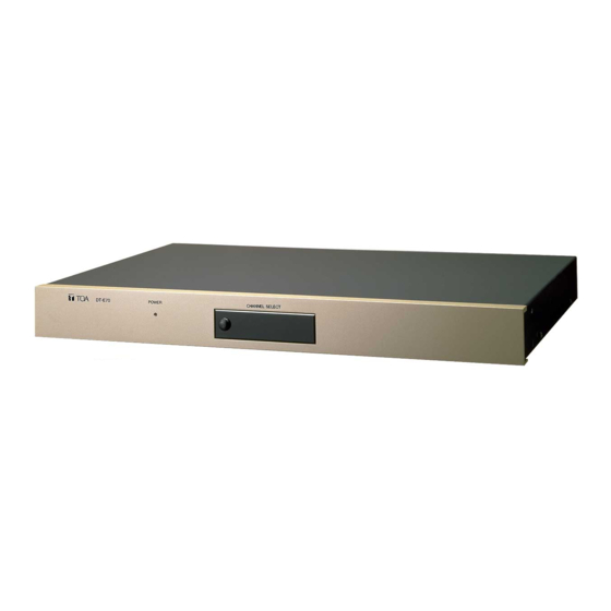
- Page 1 INSTALLATION MANUAL TOA INTERCOM SYSTEM DATA TRANSMITTING UNIT DT-E70 Please follow the instructions in this manual to obtain the optimum results from this unit. We also recommend you to keep this manual handy for future reference. TOA Corporation...
-
Page 2: Table Of Contents
Accessories ... GENERAL DESCRIPTION The DT-E70 Data Transmitting Unit is designed for exclusive use with the TOA EXES-6000 series exchanges. Functions made available from this unit when used in conjunction with the DR-B61 Data Receiving Unit and the HF-250M Intercom Station with a display include In/Out Annunciation and Calling Party Indication capabilities. -
Page 3: Part Description
PART DESCRIPTION [Front view] Release knob Switch cover CHANNEL SELECTOR SWITCH SETTING Pull the release knob forward to remove the switch cover, and the channel selector switch can be seen. Set the channel selector according to the functions. Refer to the "EX-600 and CP-66 Installation Hand Books" for the functions of each channel. -
Page 4: Installation
1. Rack mounting applications Using the supplied brackets, mount the unit in the rack. Note : The DT-E70 unit can not be mounted in the EX-610/620 exchanges. Mount it using the optional CR-271N or CR-392N cabinet rack. 2. Desk top applications Attach supplied rubber feet to holes ( 2.5mm) in the bottom surface (four places). -
Page 5: Connection
YR-801 6-pin modular jack type rosette (4-conductor) HF-250M's 24V DC power supply modular plug cord [AD-242A (2.5A)] [ Rear cover wiring example ] To other DT-E70 units YR-802 or YR-806 Interface connector EXES-6000 series exchange - 6 - DR-B61 unit... -
Page 6: Connection
1. Connect between the exchange and the data transmitting unit using the YR-806 cable (1m in length). When the unit is placed on the EX-610 or 620 exchange, use the YR-802 cable (0.4m). For connection between the exchange and the terminal box, use the YR-810 cable (for station) or the YR-801 cable (for paging or tie-line unit). -
Page 7: Time Setting
TIME SETTING Register the time to be displayed on the HF-250M's liquid crystal display into the DT-E70 unit. Time data backup switch [Rear Inside view of DT-E70E] Terminal cover TX switch [Bottom view of HF-250M] [Front view of DT-E70E] Release knob... - Page 8 Attach the front switch cover in place. Note : Make sure to switch the TX switch OFF when using the HF-250M as a usual station. If ON, the data from the DT-E70 is not displayed accurately. appears on the liquid crystal display.
-
Page 9: Yc-900 Connection
YC-900 CONNECTION Connect the YC-900's ribbon connector to the DT-E70's rear-mounted CN3 connector. Referring to the indication on the YC-900, connect the YC-900's clip terminal to the commercial rosette as shown in <Tables 1 and 2>. Connect the rosette's L1 and L2 to the BX-610 or 620 terminal box. - Page 10 Connection diagram HF-250M 6-pin modular jack type rosette (4-conductor) HF-250M 6-pin modular jack type rosette (4-conductor) YC-900 [CH6] YC-900 [CH7] - 11 - HF-250M 6-pin modular jack type rosette (4-conductor) BX-610/620 HF-250M 6-pin modular jack type rosette (4-conductor)
-
Page 11: Specifications
512 bits (32 words) 0.32 second/cycle 2 frequency FSK (frequency shift keying) Non-polar 2-conductor cable (parallel, stranded, shielded) Max. 2 km (cable with 0.65mm dia.) DR-B61 : max. 50 units/DT-E70 HF-250M : max. 16 units/DT-E70 HF-250M 0°C~40°C(32°F~104°F) Desk top or rack mounting... - Page 12 DT-E70 Please see the reverse side for English manual.
- Page 13 - 3 -...
- Page 14 - 4 -...
- Page 15 - 5 -...
- Page 16 HF-250M - 6 -...
- Page 17 [YC-900] - 7 -...
- Page 18 - 8 -...
- Page 19 - 9 -...
- Page 20 YC-900 - 10 -...
- Page 21 HF-250M - 11 -...
- Page 22 133-06-188-00...
Need help?
Do you have a question about the DT-E70 and is the answer not in the manual?
Questions and answers