Sony SSC-DC14, SSC-DC14P, SSC-DC18P - Color Video Camera Guide
- Specifications (6 pages) ,
- Operating instructions (2 pages) ,
- Catalog (46 pages)
Advertisement
Owner's Record
The model and serial numbers are located on the bottom.
Record these numbers.
Refer to these numbers whenever you call upon your Sony dealer regarding this product.


To prevent fire or shock hazard, do not expose the unit to rain or moisture.
 To avoid electrical shock, do not open the cabinet. Refer servicing to qualified personnel only.
 NOTICE FOR THE SSC-DC14
The glaphical simbol is on the unit.
This symbol is intended to alert the user to the presence of important operating and maintenance (servicing) instructions in the literature accompanying the appliance.
Features
This DC14/14P/18P color video camera is equipped with a 1/3 inch Hyper HAD (Hyper Hole-Accumulated Diode) CCD (Charge Coupled Device), and also has the following features:
- High sensitivity (Minimum illumination: 1.7 lux, F1.2)
- CCD-IRIS function
- Automatic white balance tracking and adjustment (normal/PRO)
- Compatible with DC controlled or video signal controlled auto irislenses
- Automatic backlight compensation and automatic flicker reductionthrough Smart Control. (operates when AGC switch is in the "ON" position).
- Line lock function for synchronizing though AC power source.
* Hyper HAD and Smart Control are registered trademarks of Sony Corporation
Notes on Use
Power supply
The SSC-DC14 must always be operated with a 24V AC class 2 power supply. In the U.S.A, use a Power supply which is UL Listed. In Canada, use a power supply which is CSA Certified.
The SSC-DC14P must always be operated with a 24 volts AC (50 Hz) power supply. The SSC-DC18P must always be operated with a 230V AC (50 Hz) power supply.
- When connecting the transformer, be sure to connect each lead to theappropriate terminal. Wrong connection may cause malfunction and/or damage to the video camera.
- Ground the unit or an irregular voitage may be generated in the ACpower cord and may cause malfunction and/or damage to the video camera.
Handling
Be careful not to spill water or other liquids on the unit, or allow combustible or metallic objects to fall inside the body. If used with foreign matter inside, the camera is liable to fail, or be a cause of fire or electric shock.
Operation and storage locations
Avoid aiming the camera at very bright objects such as the sun or electric lights for an extended period. Avoid operating or storing the unit in the following locations.
- Extremely hot or cold places (operating temperature –10°C to + 50°C(14°F to 122°F)
- Damp or dusty places
- Where it is exposed to rain
- Where it is subject to strong vibration
- Close to generators of powerful electromagnetic radiation such asradio or TV transmitters.
- Where it is subject to fluorescent light reflections
- Where it is subject to unstable (flickering, etc.) lighting conditions.
Care of the unit
- Remove dust or dirt on the surface of the lens or CCD with a blower
- Use a dry, soft cloth to clean the body. If it is very dirty, use a clothdampened with a small quantity of neutral detergent, then wipe dry.
- Avoid using volatile solvents such as thinners, alcohol, benzene, and insecticides. They may damage the surface finish and/or impair the operation of the camera.
Other
- When BLC is in the "ON" position, "hunting" may occur, that is, theimage may get darker and lighter as the camera "hunts" for the best exposure level. If hunting occurs, set the BLC switch to "OFF."
- If you use the CCD-IRIS function in locations where the camera is exposed to fluorescent light, a slow color change may occur.
In the event of any problems with the operation of the camera, contact your Sony dealer.
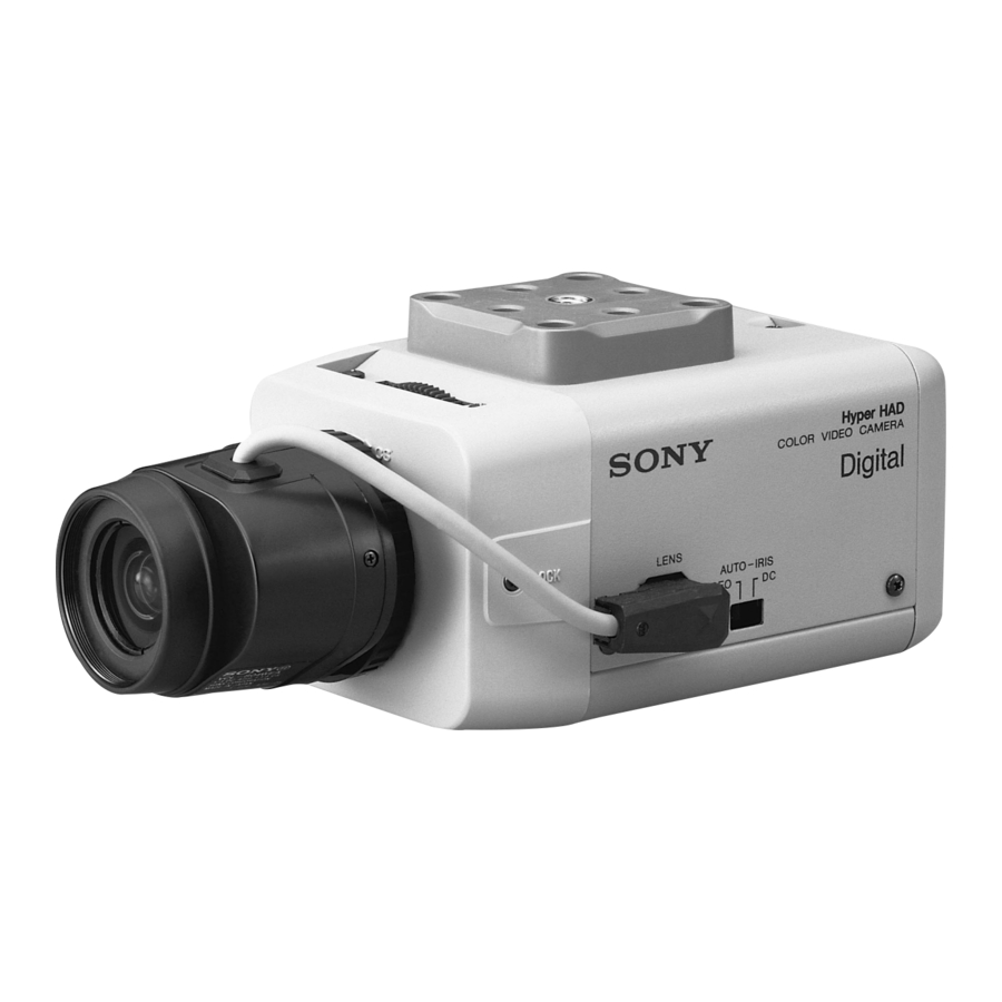
Location and Function of Parts
Top/Front/Side

- Focal length adjustment ring and locking screw
Use this ring to adjust the focal length (the distance between the lens mounting plane and the image plane).
Use the locking screw to lock the focal length. - Lens mount
Use to mount an appropriate C-mount or a CS-mount lens. To attach a C-mount/CS-mount lens, turn the focal length adjustment ring to the appropriate position. The factory setting is C mount. - Lens connector (4 pin socket)
Supplies power and control signals to an auto iris lens. - Camera mounting bracket
The mounting bracket can be attached to either the top or bottom of the camera using the four attached screws (1/4" UNC-20). - Auto iris lens selection switch (DC/Video)
Switch for selecting the control signal for the auto iris lens.
DC: For auto iris lenses controlled by DC signals
VIDEO: For auto iris lenses controlled by video signals
Notes
- When the DC/VIDEO switch is set to VIDEO, the backlightcompensation function may not work properly.
- When the DC/VIDEO switch is set to VIDEO, "hunting" may occur. Ifthis occurs, use the LEVEL L/H adjustment screw on the lens to change the incident light level. When adjusting the incident light level, set the ALC (Automatic Light Control) adjustment screw to Av.
Rear

- SYNC switch
Use this switch to set the camera synchronization mode—line lock (L.L) or internal (INT). - AGC (automatic gain control) ON/OFF switch
The automatic gain function automatically adjusts picture gain in accordance with the brightness of the subject. - Gain up switch
Switching the Gain up switch to the TURBO mode while the AGC switch![]() is on increases gain by up to 6dB over the NORM (normal) mode.
is on increases gain by up to 6dB over the NORM (normal) mode. - BLC (back lighting compensation) ON/OFF switch
When switched on, this function adjusts exposure to compensate for situations where the subject is lit from behind. - CCD-IRIS ON/OFF switch
When using a manual iris lens, the CCD-IRIS function automatically adjusts the shutter speed to maintain a suitable exposure level. - White balance mode switch
When set in the ATW (auto tracing white balance) - PRO position, the camera automatically adjusts white balance to suit the color temperature of various lighting sources, including incandescent, fluorescent and natural lighting.
When set to the ATW position, the camera automatically adjusts white balance to suit special lighting sources such as sodium lamps. - Aperture switch
Set in the "SHARP" mode to sharpen the outline and produce a clearer picture. - VIDEO OUT connector (BNC)
- Ground terminal (screw type)
- Power cable
- AC 24 V input terminals
- Video level adjustment screw
Use to adjust the video level when using a DC servo lens. - Vertical Phase adjustment screw
Use to adjust the vertical phase of cameras synchronized by line lock.
 is on increases gain by up to 6dB over the NORM (normal) mode.
Installation
Suitable lenses

The lens must be either a C- or a CS-mount type of less than 1 kg. The protrusion behind the mounting surface must be within the following limits:
 | C-mount lens |  | CS-mount lens |
 | 9 mm or less |  | 4 mm or less |
Changing the plug on an auto iris lens cable

The camera is supplied with a LENS connector for inserting the power/ control cable of an auto iris lens. Before connecting an auto iris lens, however, you first have to replace the lens cable plug with the one supplied with this camera. Replace as follows:
- Detach the old plug from the lens cable.
- Solder the wires to the pins of the new plug. (For cable pin assignment, refer to the instruction manual for the lens.)
| Cover | ||
| Lens cable | ||
| Rib (If the cable is thick, cut this off.) | ||
| Plug (unit accessory) | ||
 | Pin 4 | Video signal control | Ground |
| DC control | DRV – | ||
 | Pin 2 | Video signal control | Not used |
| DC control | CONT + | ||
 | Pin 1 | Video signal control | Power supply |
| DC control | CONT – | ||
 | Pin 3 | Video signal control | Video signal |
| DC control | DRV + | ||
Fitting the lens

- Unscrew the lens mount cap.
- Screw in the lens, and turn it until it is secured.
- Insert the lens plug in the LENS connector.
When fitting a manual-iris lens, omit step 3. - Adjust the focal length by turning the C/CS adjustment ring.
- Tighten the locking screw.

When mounting the lens, loosen the securing nut on the side and turn the focal length adjustment to the "C" position. Mounting a C-mount lens with the adjustment ring in the "CS" position may damage the optical filter.
Keep the lens mount cap on the camera when not attaching a lens.
Installing the device
When attaching the camera to a ceiling bracket or tripod, attach the supplied mounting bracket. The bracket may be attached to either the top or bottom of the camera. Use the supplied 1/4'' UNC-20 screw to attach the camera to the tripod or ceiling bracket.
Connections

Using an internal synchronization signal.
- Set the L.L/INT switch to INT (internal synchronization).
- Connect with VIDEO OUT connector.
- 75-ohm coaxial cable
- Connect with VIDEO IN connector on a video monitor, etc.
- to power supply (SSC-DC14/14P) /to a wall outlet (SSC-DC18P)
- Power cord
- to AC 24V terminals 1 and 2 (SSC-DC14/14P)
When using an external (L.L) synchronization signal, set the L.L/INT switch to L.L and make connections as above.
Phase Adjustment

When using more than one camera, connect to a camera switcher and set the vertical phase range as follows:
- Camera switcher
- Monitor
- Vertical phase
- Adjustable range
Vertical phase

The picture may roll vertically if the vertical phase is not set. To adjust the vertical phase, turn the V PHASE screw at the back of the camera.
CCD Characteristics
The following conditions may be observed when using a CCD camera are not due to any fault within the camera.
Vertical smear
This phenomenon occurs when viewing a very bright object.
Patterned noise
This is a fixed pattern which may appear over the entire monitor screen when the camera is operated a high temperature.
Jagged picture
When viewing stripes, straight lines, or similar patterns, the image on the screen may appear jagged.
Specifications
| Image device | 1/3" interline transfer type CCD | |
| Effective picture elements | SSC-DC14: 768 (horizontal) × 494 (vertical) SSC-DC14P/18P: 752 (horizontal) × 582 (vertical) | |
| Lens mount | C-mount/CS-mount adjustable | |
| Signal system | NTSC color system (SSC-DC14); PAL color system (SSC-DC14P/18P) | |
| Synchronization system | Internal/line lock | |
| Horizontal resolution | 470 lines | |
| Minimum illumination | 1.7 lux, F1.2 (with AGC set to ON in TURBO mode) | |
| Video output | 1 Vp-p, 75 ohm, negative sync | |
| Video S/N | 50 dB (with AGC set to OFF) | |
| White balance | ATW/ATW PRO (switchable) | |
| Automatic gain control (AGC) | Switchable: ON (TURBO mode) ON (NORM)/OFF | |
| Power requirements | SSC-DC14 | AC 24 V (60 Hz) |
| SSC-DC14P | AC 24 V (50 Hz) | |
| SSC-DC18P | AC 220-240V (50 Hz) | |
| Power consumption | Less than 4.5 W (SSC-DC14/14P), 5.5 W (SSC-DC18P) | |
| Operating temperature | –10°C to +50°C (14°F to 122°F) | |
| Operating humidity | 20 to 80% | |
| Storage temperature | –40°C to +60°C (–40°F to 140°F) | |
| Storage humidity | 20 to 80% | |
| Shock resistance | 70 G | |
| Mass | SSC-DC14/14P: 550g, SSC-DC18P: 770 g (1 lb 9 oz) | |
| Dimensions | 70 × 57 × 130 (w/h/d) mm (2 7/8 × 2 1/4 × 5 1/8 inches) | |
Design and specifications are subject to change without notice.
Sony Corporation © 1996

Documents / ResourcesDownload manual
Here you can download full pdf version of manual, it may contain additional safety instructions, warranty information, FCC rules, etc.
Download Sony SSC-DC14, SSC-DC14P, SSC-DC18P - Color Video Camera Guide
Advertisement


Need help?
Do you have a question about the SSC-DC14 and is the answer not in the manual?
Questions and answers