Sony XCL-S600, XCL-S900, XCL-S600C, XCL-S900C Operating Manual
- Brochure (4 pages) ,
- Technical manual (54 pages)
Advertisement
- 1 Getting started
- 2 When installing the camera
- 3 Notes on Operation
-
4
Overview
- 4.1 DIGITAL IF connector
- 4.2 High image quality
- 4.3 Various settings
- 4.4 Electronic shutter function
- 4.5 External trigger shutter function
- 4.6 Partial scan
- 4.7 Body fixing
- 4.8 LUT (Look Up Table)
- 4.9 Switching an Output Bit Length
- 4.10 Binning (XCL-S600/S900)
- 4.11 White balance control (XCL-S600C/S900C)
- 4.12 Defect correction
- 4.13 Shading correction
- 5 System Components
- 6 Connection Example
- 7 Documents / Resources
Getting started
These operating instructions cover several models of digital video camera module:
- XCL-S600/S900 (monochrome models)
- XCL-S600C/S900C (color models)
When installing the camera

Fig. A
When you install the camera with various peripheral devices and if the devices have different ground electric potential, ground only one device. In case there is an ground electric potential difference, the camera may be damaged.
 DIGITAL IF connector
 Host device (e.g., Computer)
 Ground electric potential difference
 DC IN connector
 Abnormal electricity
 Power supply unit (DC-700/700CE)
* If the camera module interface board within the host device (e.g., Computer) supports PoCL (Power over Camera Link), you can operate the camera even if the items within the dotted lines are not connected.
Notes on Operation
Power supply
You can supply power to this unit using the following methods.
Using the DC IN connector
You can supply power via the DC IN connector using the power adapter.
Use DC-700/700CE which is the stable power source free from ripple or noise.
Foreign bodies
Be careful not to spill liquids, or drop any flammable or metal objects in the camera body.
Locations for operation and storage
Avoid operation or storage in the following places.
- Extremely hot or cold locations. Recommended temperature range is 0°C to 40°C (32°F to 104°F)
- Locations subject to strong vibration or shock.
- Near generators of strong electromagnetic radiation such as TV or radio transmitters.
Care
Use a blower to remove dust from the surface of the lens or optical filter. Clean the exterior with a soft, dry cloth. If the camera is very grimy, apply a cloth soaked in a mild detergent then wipe with a dry cloth. Do not apply organic solvents such as alcohol or benzine which may damage the finish.
 Note on laser beams
Laser beams may damage a CCD. You are cautioned that the surface of a CCD should not be exposed to laser beam radiation in an environment where a laser beam device is used.
Overview
Before operating the unit, please read this manual thoroughly and retain for future reference.
This unit is a digital video camera module that outputs digital images utilizing LVDS via the DIGITAL IF connector.
DIGITAL IF connector
Equipped with a Camera Link standard mini connector. The unit can output a detailed and high speed digital image.
High image quality
All cameras feature a progressive scan CCD for high-resolution images. Both cameras produce high-resolution images. By adopting square pixels, images can be processed using the original aspect ratio without a converting procedure. The following models and their CCDs are shown below.
| Model name | Pixel count |
| XCL-S600/S600C | 6,000,000-pixel CCD |
| XCL-S900/S900C | 9,000,000-pixel CCD |
Various settings
Sending a command from the host device allows various settings, including the following.
- Gain
- Shutter
- Partial scan
- Trigger control
- LUT (Look Up Table)
- Output: 8/10/12-bit or RGB 24-bit
- Defect correction
- Shading correction
Electronic shutter function
Set anywhere from 1/100,000 sec to 2 sec in 1 µs increments.
External trigger shutter function
By synchronizing with an external trigger signal, any shutter timing can be used.
Partial scan
The camera module can limit the number of video output lines to achieve high frame rates, enabling high-speed image processing.
Body fixing
The screw holes to install the camera module are located under the front panel (the CCD reference plane). Installing the camera module on the front panel minimizes deviation of the optical axis.
LUT (Look Up Table)
You can switch to OFF or ON. When set to OFF, you can select from five preset values, such as inversion, binarization, any of five-point approximation, etc.
Switching an Output Bit Length
You can select 8-bit output, 10-bit output, or 12-bit output.
For color models, you can also select an RGB 24-bit output.
Binning (XCL-S600/S900)
Sensitivity can be doubled by combining two pixels aligned vertically. For the standard output frame rate, XCL-S600 can be set 1.97× (CCD scan 4ch/2ch/1ch), XCL-S900 can be set 1.98× (CCD scan 4ch) or 2× (CCD scan 1ch). Sensitivity can be doubled by combining two pixels align horizontally. You can set horizontal and vertical binning at the same time.
White balance control (XCL-S600C/S900C)
You can adjust the R and B level against G level to adjust the white balance. This unit is also equipped with the one-push white balance function, by which the camera can automatically adjust the white balance.
Defect correction
The unit includes a function to reduce sensor defects, and can be set to ON or OFF.
Shading correction
The unit includes a function to correct shading, resulting from a light source or a particular lens, and can be set to ON or OFF.
System Components

Fig. B
The video camera module system comprises the following optional products (available separately).
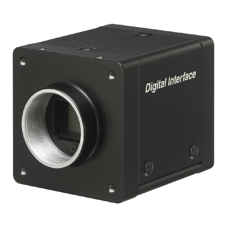
 Video Camera Module
This is a small-size, high-resolution, video camera module using a progressive scan CCD image sensor.
 CCXC-12P02N (2 m, 6.6 ft)/05N (5 m, 16.4 ft)/10N (10 m, 32.8 ft)/ 25N (25 m, 82 ft) camera cable
This is attached to the DC IN connector of the camera module and is used for power supply and exchange of trigger signals.
 C-mount lens
Use a suitable lens to fit the camera pixel count.
 DC-700/700CE camera adaptor
This is connected to the camera module to enable power supply from ordinary AC power source.
 VCT-ST70I tripod adaptor
This attaches to the bottom of the camera module to fix the camera module to a tripod.
 Camera module interface board
Install the board in a PCI bus slot in devices such as a computer. Select a commercially available interface board compatible with the Camera Link feature.
Due to the performance of the board, the frame rate may become low according to lack of processing capacity. To have this product output frames at the highest speed, use a board corresponding to PCI-Express.
Performance may also be dependent on the host device (e.g., Computer), so consult the dealer if images are not displayed properly.
 Camera Link cable
This cable connects to the DIGITAL IF connector on the rear panel of the camera module. Image/control signals are transmitted via this cable.
Select a proper cable as the maximum usable length of a cable differs due to the attribute of each cable.
Spotted noise may appear in a specific brightness in the window according to the attribute of the cable. If this noise is an obstacle, shorten the cable.
Connection Example

Connecting DC-700/700CE (not supplied)
Connect the camera module to the power via the camera adaptor DC-700/700CE. For details on the camera adaptor DC-700/700CE, see the DC-700/700CE Instruction Manual.
 C-mount lens
 Camera cable (e.g. CCXC-12P05N)
 TRIG generator, Image processor
 To DC IN connector
 To CAMERA connector
 To AC IN connector
 To AC power source

Documents / ResourcesDownload manual
Here you can download full pdf version of manual, it may contain additional safety instructions, warranty information, FCC rules, etc.
Download Sony XCL-S600, XCL-S900, XCL-S600C, XCL-S900C Operating Manual
Advertisement


Need help?
Do you have a question about the XCL-S600 and is the answer not in the manual?
Questions and answers