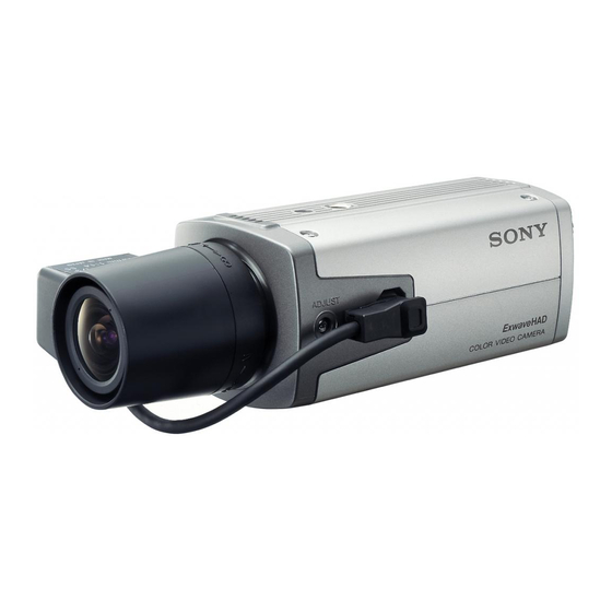
Sony SSC-M183 Service Manual

Sony SSC-M183 Service Manual

Black and white video camera & color video camera
Hide thumbs Also See for SSC-M183:

Advertisement

BLACK AND WHITE VIDEO CAMERA & COLOR VIDEO CAMERA
SSC-M183/M183CE
SSC-M188CE
SSC-M383/M383CE
SSC-M388CE
SSC-DC193/DC193P
SSC-DC198P
SSC-DC393/DC393P
SSC-DC398P
SERVICE MANUAL
1st Edition

Advertisement

Table of Contents
loading

Summary of Contents for Sony SSC-M183

  • Page 1 BLACK AND WHITE VIDEO CAMERA & COLOR VIDEO CAMERA SSC-M183/M183CE SSC-M188CE SSC-M383/M383CE SSC-M388CE SSC-DC193/DC193P SSC-DC198P SSC-DC393/DC393P SSC-DC398P SERVICE MANUAL 1st Edition...
  • Page 2 électrique, d’incendie ou de blessure n’effectuer que les réparations indiquées dans le mode d’emploi à moins d’être qualifié pour en effectuer d’autres. Pour toute réparation faire appel à une personne compétente uniquement. SSC-M183/M183CE/M188CE/M383/M383CE/M388CE SSC-DC193/DC193P/DC198P/DC393/DC393P/DC398P...
  • Page 3: Table Of Contents

    Adjustment Software ..............2-4 2-3-2. Preparation for Adjustment ............2-5 2-3-3. Reading of Parameter ..............2-5 2-3-4. 0 dB Adjustment ................ 2-6 2-3-5. Color Reproduction Adjustment ..........2-6 2-3-6. Writing ..................2-7 2-4. Correction of Residual Point Noise ............. 2-7 SSC-M183/M183CE/M188CE/M383/M383CE/M388CE SSC-DC193/DC193P/DC198P/DC393/DC393P/DC398P...
  • Page 4 Black and White Camera ................3-1 3-2. Color Camera ....................3-4 4. Spare Parts 4-1. Notes on Repair Parts .................. 4-1 5. Block Diagrams 5-1. Color Camera ....................5-2 Overall ....................5-2 5-2. B/W Camera ....................5-4 Overall ....................5-4 SSC-M183/M183CE/M188CE/M383/M383CE/M388CE SSC-DC193/DC193P/DC198P/DC393/DC393P/DC398P...
  • Page 5: Manual Structure

    Manual Structure Purpose of this manual This manual is the Service Manual of the Black and White Video Camera & Color Video Camera SSC-M183/M183CE/M188CE/M383/M383CE/M388CE/DC193/ DC193P/DC198P/DC393/DC393P/DC398P. This manual contains service overview, adjustment, troubleshooting, spare parts and block diagrams. Related manuals In addition to this Service Manual, the following manuals is provided.
  • Page 7: Service Overview

    F2001 board PB-2001/PC-2001 board Board name Use model AC-230board SSC-M188CE/M388CE Description Factory default setting SSC-DC198P/DC398P Auto iris lens selection switch AC-24 board SSC-M183 Sync switch SSC-M183CE AGC ON/OFF switch SSC-M383 BLC ON/OFF switch SSC-M383CE CCD-IRIS ON/OFF switch SSC-DC193 SSC-DC193P For SSC-DC198P/DC398P/M188CE/M388CE...
  • Page 8: Installation/Removal Of Cabinet

    1. Remove the six screws, then remove the rear panel. Top cover B 2x5 B 2x5 Camera screw Rear panel B 2x5 Top chassis PTP 2x5 4. Attach the top cover in the reverse order of steps 1 to SSC-M183/M183CE/M188CE/M383/M383CE/M388CE SSC-DC193/DC193P/DC198P/DC393/DC393P/DC398P...
  • Page 9: Front Cover Assembly

    1-3-2. Front Cover Assembly For SSC-DC193/DC193P/DC198P/DC393/DC393P/ DC398P For SSC-M183/M183CE/M188CE/M383/M383CE/ 1. Remove the top cover. (Refer to Section 1-3-1.) M388CE 2. Remove the two screws. 1. Remove the top cover. (Refer to Section 1-3-1.) 3. Move portion A of the front cover assembly in the 2.
  • Page 10 Before attaching the rear chassis assembly, securely attach 8. Attach the bottom cover in the reverse order of steps 1 the AC-230 board. to 7. 7. Attach the bottom cover in the reverse order of steps 1 to 6. SSC-M183/M183CE/M188CE/M383/M383CE/M388CE SSC-DC193/DC193P/DC198P/DC393/DC393P/DC398P...
  • Page 11: Installation/Removal Of Board

    8. Remove one screw and two solders, then remove the R-2001 board. 1-4-1. R-2001 Board 9. Remove the nut, then remove the toothed washer, earth lug and BNC connector from the rear chassis. For SSC-M183/M183CE/M383/M383CE/DC193/ DC193P/DC393/DC393P Rear chassis 1. Remove the top cover. (Refer to Section 1-3-1.) BNC connector 2.
  • Page 12 Earth lug Toothed washer Rear chassis assembly Harness CN603 Two solders Solder 10. Attach the R-2001 board in the reverse order of steps 1 to 9. Harness Solder AC-230 board CN203 (PB-2001 board) CN204 (PC-2001 board) PB-2001/PC-2001 board SSC-M183/M183CE/M188CE/M383/M383CE/M388CE SSC-DC193/DC193P/DC198P/DC393/DC393P/DC398P...
  • Page 13: Pb-2001/Pc-2001 Board

    1-4-2. PB-2001/PC-2001 Board Installation 1. Attach the AC-24 board in the reverse order of steps 6 For SSC-M183/M183CE/M383/M383CE/DC193/ and 7 of the Removal. DC193P/DC393/DC393P 2. Insert the marking section of the PB-2001/PC-2001 board into the groove of the bottom chassis, then Removal attach in the direction indicated by the arrow.
  • Page 14 7. Remove the solder from the connector (CN602) on the AC-230 board, then remove the PB-2001/PC-2001 board. Solder CN602 CN602 Bottom chassis Claw Solder Harness Harness PB-2001 /PC-2001 board PB-2001 /PC-2001 board AC-230 board AC-230 board Bottom chassis SSC-M183/M183CE/M188CE/M383/M383CE/M388CE SSC-DC193/DC193P/DC198P/DC393/DC393P/DC398P...
  • Page 15: Ac-24/230 Board

    1-4-3. AC-24/230 Board Installation 1. Attach the AC-24 board in the reverse order of steps 5 For SSC-M183/M183CE/M383/M383CE/DC193/ and 6. DC193P/DC393/DC393P 2. Insert the marking section of the AC-24 board into the groove of the bottom chassis, then attach in the Removal direction indicated by the arrow.
  • Page 16 6. Remove the solder from the (CN602) connector on the AC-230 board Groove AC-230 board, then remove the AC-230 board. Solder CN602 Harness Bottom chassis Claw PB-2001 /PC-2001 board AC-230 board AC-230 board B 2x5 Bottom chassis 1-10 SSC-M183/M183CE/M188CE/M383/M383CE/M388CE SSC-DC193/DC193P/DC198P/DC393/DC393P/DC398P...
  • Page 17: Ccd Assembly

    1-5. CCD Assembly For SSC-M188CE/M388CE/DC198P/DC398P For SSC-M183/M183CE/M383/M383CE/DC193/ When removing the screw of the retaining plate, be careful DC193P/DC393/DC393P of the spring between the front cover and the CCD cover since it may pop up. When removing the screw of the retaining plate, be careful 1.
  • Page 18: Plate Reinforcement

    1-6. Plate Reinforcement For SSC-M183/M183CE/M383/M383CE/DC193/ DC193P/DC393/DC393P 1. Remove the top cover. (Refer to Section 1-3-1.) 2. Remove the front cover assembly. (Refer to Section 1- 3-2.) 3. Remove the rear chassis assembly. (Refer to Section 1- 3-3.) 4. Remove the PB-2001 board. (Refer to Section 1-4-2.) 5.
  • Page 19: Confirmation And Adjustment

    ..For the color reproduction adjustment This scale is printed on the rear cover paper. NBC-2001 J-6432-790-A . Oscilloscope . Digital voltmeter . Vectorscope . Waveform Monitor . Color Monitor . Personal computer . RS-232C cable (Straight) SSC-M183/M183CE/M188CE/M383/M383CE/M388CE SSC-DC193/DC193P/DC198P/DC393/DC393P/DC398P...
  • Page 20: Connection Diagram

    75 Z termination Adjusting tool board Personal computer . DC12 V/AC24 V (60 Hz) CN203 CN205 SSC-DC193/DC393 . DC12 V/AC24 V (50 Hz) SSC-DC193P/DC393P CL202 CL201 . AC220 to 240 V (50 Hz) SSC-DC198P/DC398P CT301 PC-2001 board (Side B) SSC-M183/M183CE/M188CE/M383/M383CE/M388CE SSC-DC193/DC193P/DC198P/DC393/DC393P/DC398P...
  • Page 21: Confirmation

    Adjustment is not required. When there is a point that meets the specification of 3 after adjusting the lens aperture within the range of specification of 2, this means that the adjustment is correctly made. Make adjustment. Adjustment is completed. SSC-M183/M183CE/M188CE/M383/M383CE/M388CE SSC-DC193/DC193P/DC198P/DC393/DC393P/DC398P...
  • Page 22: Confirmation Of Color Reproduction Adjustment

    Basically, set only the port to be connected. Other settings are automatically set as follows by the software when “BoxCam.exe” is executed. . Transmission speed: 9600bps . Data length: 8 bits . Parity: None . Start bit: . Stop bit: . Flow control: None SSC-M183/M183CE/M188CE/M383/M383CE/M388CE SSC-DC193/DC193P/DC198P/DC393/DC393P/DC398P...
  • Page 23: Preparation For Adjustment

    3. Turn on the power of camera again and check that the screen is displayed. Then, click the OK button of the above message. Name of switch SSC-DC193 SSC-DC198P SSC-DC193P SSC-DC398P SSC-DC393 SSC-DC393P Sync switch — AGC ON/OFF switch BLC ON/OFF switch CCD IRIS ON/OFF switch SSC-M183/M183CE/M188CE/M383/M383CE/M388CE SSC-DC193/DC193P/DC198P/DC393/DC393P/DC398P...
  • Page 24: Db Adjustment

    Specification: B = 800 reproduction (smaller area) in the same way as step 6. Make adjustment so that R and YL are within the small area. Measuring point: Adjustment method: PC keys Oscilloscope: AC200 mV NBC-2001 10 µSec J-6432-790-A SSC-M183/M183CE/M188CE/M383/M383CE/M388CE SSC-DC193/DC193P/DC198P/DC393/DC393P/DC398P...
  • Page 25: Writing

    6. Click the “Defect Compensation Mode” button. The current data is read from the camera. 7. After completion of the reading, the following message is displayed. SSC-M183/M183CE/M188CE/M383/M383CE/M388CE SSC-DC193/DC193P/DC198P/DC393/DC393P/DC398P...
  • Page 26 When the spot is large in size, place a checkmark to each checkbox of “2 Point” of Address1 and Address2. Then, the correction range can be indicated by two points in the lateral direction. SSC-M183/M183CE/M188CE/M383/M383CE/M388CE SSC-DC193/DC193P/DC198P/DC393/DC393P/DC398P...
  • Page 27: Troubleshooting

    Section 3 Troubleshooting 3-1. Black and White Camera Applicable models: SSC-M183/M183CE/M188CE/M383/M383CE/M388CE 1. Image is too bright. Image is too bright. When the image is not improved Normal Position of the after the AGC switch on the rear Type of the used lens?
  • Page 28 Pin 1 = 15 V Pin 2 = 9 V Pin 3 = 5 V Pin 5 = _7 V Oscillating? X201: Frequency (INT) SSC-M183 (19.06993 MHz) SSC-M183CE (18.9375 MHz) SSC-M383 (28.63636 MHz) SSC-M383CE (28.375 MHz) CL202 (LL): Voltage Is the output (29 ±0.5 V)
  • Page 29 CCD-IRIS When the image is not improved after the AGC switch on the rear panel is set to AGC side, readjust with the LEVEL volume. Open the lens aperture. Readjust the LEVEL volume. To B SSC-M183/M183CE/M188CE/M383/M383CE/M388CE SSC-DC193/DC193P/DC198P/DC393/DC393P/DC398P...
  • Page 30: Color Camera

    Adjust the lens aperture Reconnect the cable of Is the image the servo lens. correctly displayed? To A When the image is not improved Adjust correctly with the after adjusting with the LEVEL LEVEL volume. volume, replace the rear board. SSC-M183/M183CE/M188CE/M383/M383CE/M388CE SSC-DC193/DC193P/DC198P/DC393/DC393P/DC398P...
  • Page 31 Check the image after disconnecting the flexible flat cable from the main (PC) board and the front (F) board. Is the noise level of the image higher than Replace the main (PC) board. that under normal state? Replace the front (F) board. SSC-M183/M183CE/M188CE/M383/M383CE/M388CE SSC-DC193/DC193P/DC198P/DC393/DC393P/DC398P...
  • Page 32 VIDEO servo lens: Lens LEVEL Manual lens When the image is not improved Is the image Adjust the lens aperture. after adjusting with the LEVEL correctly displayed? volume, replace the rear board. Adjust with the LEVEL volume. SSC-M183/M183CE/M188CE/M383/M383CE/M388CE SSC-DC193/DC193P/DC198P/DC393/DC393P/DC398P...
  • Page 33: Spare Parts

    Therefore, specified parts should be used in the case of replacement. 2. Standardization of Parts Some repair parts supplied by Sony differ from those used for the unit. These are because of parts common- ality and improvement. Parts list has the present standardized repair parts.
  • Page 34 Overall Block SSC-M183/M183CE/M383/M383CE B 2x5 B 2x5 B 2x5 B 2x5 PTP 2x4 B 2x5 B 2x5 B 2x5 PTP 2x4 B 2x5 B 2x5 B 2x5 B 2x5 B 2x5 SSC-M183/M183CE/M188CE/M383/M383CE/M388CE SSC-DC193/DC193P/DC198P/DC393/DC393P/DC398P...
  • Page 35 Part No. SP Description 1-793-002-11 s CONNECTOR, COAXIAL (BNC TYPE) 2-042-385-00 s CAP,LENS MOUNT 9-885-021-23 s MOUNTED C.BOARD,AC-24-B 9-885-021-24 s MOUNTED C.BOARD,PB-2001-183 (for SSC-M183) 9-885-021-25 s MOUNTED C.BOARD,PB-2001-183CE (for SSC-M183CE) 9-885-021-68 s MOUNTED C.BOARD,PB-2001-383 (for SSC-M383) 9-885-021-69 s MOUNTED C.BOARD,PB-2001-383CE (for SSC-M383CE) 9-885-021-27 s MOUNTED C.BOARD,R-2001-183...
  • Page 36 Overall Block SSC-M188CE/M388CE B 2x5 B 2x5 B 2x5 B 2x5 PTP 2x4 B 2x5 B 2x5 PTP 2x4 B 2x5 B 2x5 B 2x5 B 2x5 B 2x5 SSC-M183/M183CE/M188CE/M383/M383CE/M388CE SSC-DC193/DC193P/DC198P/DC393/DC393P/DC398P...
  • Page 37 (for SSC-M188CE) 9-885-021-73 s COVER (BOTTOM) B&W HR (for SSC-M388CE) 9-885-021-42 s CHASSIS (TOP) 9-885-021-43 s CHASSIS (BOTTOM) 9-885-021-49 s SCREW (PLATFORM) 1-769-412-13 s CORD,POWER (IEC) 3-679-362-01 s SCREW +B M2X4 7-621-771-06 s SCREW +B2X5 7-685-102-19 s SCREW +PTP2X4 SSC-M183/M183CE/M188CE/M383/M383CE/M388CE SSC-DC193/DC193P/DC198P/DC393/DC393P/DC398P...
  • Page 38 Overall Block SSC-DC193/DC193P/DC393/DC393P B 2x5 B 2x5 B 2x5 B 2x5 PTP 2x4 B 2x5 B 2x5 B 2x5 PTP 2x4 B 2x5 B 2x5 B 2x5 B 2x5 B 2x5 SSC-M183/M183CE/M188CE/M383/M383CE/M388CE SSC-DC193/DC193P/DC198P/DC393/DC393P/DC398P...
  • Page 39 (for SSC-DC393) 9-885-021-66 s CCD ASSY HR, PAL (for SSC-DC393P) 9-885-021-61 s COVER (BOTTOM) SR (for SSC-DC193/DC193P) 9-885-021-67 s COVER (BOTTOM) COLOR HR (for SSC-DC393/DC393P) 3-679-362-01 s SCREW +B M2X4 7-621-771-06 s SCREW +B2X5 7-685-102-19 s SCREW +PTP2X4 SSC-M183/M183CE/M188CE/M383/M383CE/M388CE SSC-DC193/DC193P/DC198P/DC393/DC393P/DC398P...
  • Page 40 Overall Block SSC-DC198P/DC398P B 2x5 B 2x5 B 2x5 B 2x5 PTP 2x4 B 2x5 B 2x5 PTP 2x4 B 2x5 B 2x5 B 2x5 B 2x5 B 2x5 SSC-M183/M183CE/M188CE/M383/M383CE/M388CE SSC-DC193/DC193P/DC198P/DC393/DC393P/DC398P...
  • Page 41 9-885-021-66 s CCD ASSY HR, PAL (for SSC-DC398P) 9-885-021-61 s COVER (BOTTOM) SR (for SSC-DC198P) 9-885-021-67 s COVER (BOTTOM) COLOR HR (for SSC-DC398P) 1-769-412-13 s CORD,POWER (IEC) 3-679-362-01 s SCREW +B M2X4 7-621-771-06 s SCREW +B2X5 7-685-102-19 s SCREW +PTP2X4 SSC-M183/M183CE/M188CE/M383/M383CE/M388CE SSC-DC193/DC193P/DC198P/DC393/DC393P/DC398P...
  • Page 43: Block Diagrams

    Section 5 Block Diagrams SSC-M183/M183CE/M188CE/M383/M383CE/M388CE SSC-DC193/DC193P/DC198P/DC393/DC393P/DC398P...
  • Page 44: Color Camera

    V DRIVER NAND IC302 IC301 LPF (H/V_CMP) EEPROM CN205 8CH D/A CONV IC302 6, 8 OSC SEL IC206, Q207 VS-SERVO CN203 Q208, 15 V Q209, Q212 3.3 V _7 V IC208, Q210 DC-SERVO CONTROL CN202 IC210 1, 3 SSC-M183/M183CE/M188CE/M383/M383CE/M388CE SSC-DC193/DC193P/DC198P/DC393/DC393P/DC398P...
  • Page 45 +9 V CN503 1RV502 LEVEL 1RV501 V-PHASE IC101 or Q601 AC230/AC24 BOARD SWITCHING CONTROL CN103 CN603 AC24V/DC12V T101 or T601 For SSC-M183/ DC-DC M183CE/M383/ POWER TRANS SWITCHING CONVERTER CN101 M383CE/DC193/ CN601 DC193P/DC393/ Q101, Q102 or Q601 DC393P F101 CN102 IC107 or IC605...
  • Page 46: B/W Camera

    CN203 L.P.F IC207 SHD1 20/24 SHD2/SHP CLP1 γ OUT CLP2 Q203- Q206 SYNC IC208 SHARPNESS PROCESS Q208, Q209 Q210 IRIS DRIVER DRV IN IRIS CONTROL CN204 IC209 CONT(_) /+9V CONT(+) /NC DRIVE (+) /VIDEO DRIVE (_) /GND LENS SSC-M183/M183CE/M188CE/M383/M383CE/M388CE SSC-DC193/DC193P/DC198P/DC393/DC393P/DC398P...
  • Page 47: Overall

    +9 V CN503 1RV502 LEVEL 1RV501 V-PHASE IC101 or Q601 AC230/AC24 BOARD SWITCHING CONTROL CN103 CN603 AC24V/DC12V T101 or T601 For SSC-M183/ DC-DC M183CE/M383/ POWER TRANS SWITCHING CONVERTER CN101 M383CE/DC193/ CN601 DC193P/DC393/ Q101, Q102 or Q601 DC393P F101 CN102 IC107 or IC605...
  • Page 48 VECTORSCOPE SCALE Copy on a transparent sheet. NBC-2001 J-6432-790-A SSC-M183/M183CE/M188CE/M383/M383CE/M388CE SSC-DC193/DC193P/DC198P/DC393/DC393P/DC398P...
  • Page 49 2 V AC range are suitable. (See Fig. A) To Exposed Metal Parts on Set 0.15 µ F 1.5 k Z voltmeter (0.75V) Earth Ground Fig A. Using an AC voltmeter to check AC leakage. SSC-M183/M183CE/M188CE/M383/M383CE/M388CE SSC-DC193/DC193P/DC198P/DC393/DC393P/DC398P...
  • Page 50 SSC-M183 (UC) SSC-M183CE (CE) SSC-M188CE (CE) SSC-M383 (UC) SSC-M383CE (CE) SSC-M388CE (CE) SSC-DC193 (UC) SSC-DC193P (CE) SSC-DC198P (CE) SSC-DC393 (UC) SSC-DC393P (CE) Printed in Japan Sony Corporation SSC-DC398P (CE) E 2002. 5 22 B&P Company 9-955-358-01 ©2002...

Table of Contents