SONY XC-555/P - CCD Color Video Camera Module Operating Instructions
- Technical manual (28 pages) ,
- Specifications (2 pages)
Advertisement
Owner's Record
The model and serial numbers are located on the bottom.
Record the serial number. Refer to these numbers whenever you call upon your Sony dealer regarding this product.

To prevent fire or shock hazard, do not expose the unit to rain or moisture.
To avoid electrical shock, do not open the cabinet. Refer servicing to qualified personnel only.
 This symbol is intended to alert the user to the presence of important operating and maintenance (servicing) instructions in the literature accompanying the appliance.
For the customers in the USA
This equipment has been tested and found to comply with the limits for a Class A digital device, pursuant to Part 15 of the FCC Rules. These limits are designed to provide reasonable protection against harmful interference when the equipment is operated in a commercial environment. This equipment generates, uses, and can radiate radio frequency energy and, if not installed and used in accordance with the instruction manual, may cause harmful interference to radio communications. Operation of this equipment in a residential area is likely to cause harmful interference in which case the user will be required to correct the interference at his own expense.
You are cautioned that any changes or modifications not expressly approved in this manual could void your authority to operate this equipment.
The shielded interface cable recommended in this manual must be used with this equipment in order to comply with the limits for a digital device pursuant to Subpart B of Part 15 of FCC Rules.
This device complies with Part 15 of the FCC Rules. Operation is subject to the following two conditions: (1) This device may not cause harmful interference, and (2) this device must accept any interference received, including interference that may cause undesired operation.
For customers in Canada
This Class A digital apparatus complies with Canadian ICES-003.
For the customers in Europe

This is a Class A product. In a domestic environment this product may cause radio interference in which case the user may be required to take adequate measures.
Precautions
This section briefly explains the functions for these accessories.
Operating and storage locations
Do not keep the camera aimed at very bright sources (electric lights, the sun, and so on). Doing so may cause discoloring of the CCD color filter. Also, avoid operating or storing the camera under the following conditions.
- Extremely hot or cold places (operating temperature 0°C to 40°C (32°F to 104°F).
- Locations exposed to direct sunlight, or close to central heating units
- Dusty places
- Locations subject to strong vibration
- Near a TV or radio station that radiates high-powered radio frequencies
Do not subject the camera to strong impacts
Be careful not to drop the unit, or subject it to other shocks, which could cause it to malfunction.
Transportation
Save the original carton and associated packing materials. They will be useful when you transport or ship the camera.
Cleaning
- Remove dust or dirt on the surface of the lens or optical filter with a blower.
- Clean the body with a dry soft cloth. If it is very dirty, use a cloth dampened with a small quantity of neutral detergent, then wipe dry. Avoid the use of volatile solvents such as thinners, alcohol, benzene, and insecticides. They may damage the surface finish, or impair the operation of the camera.
Features
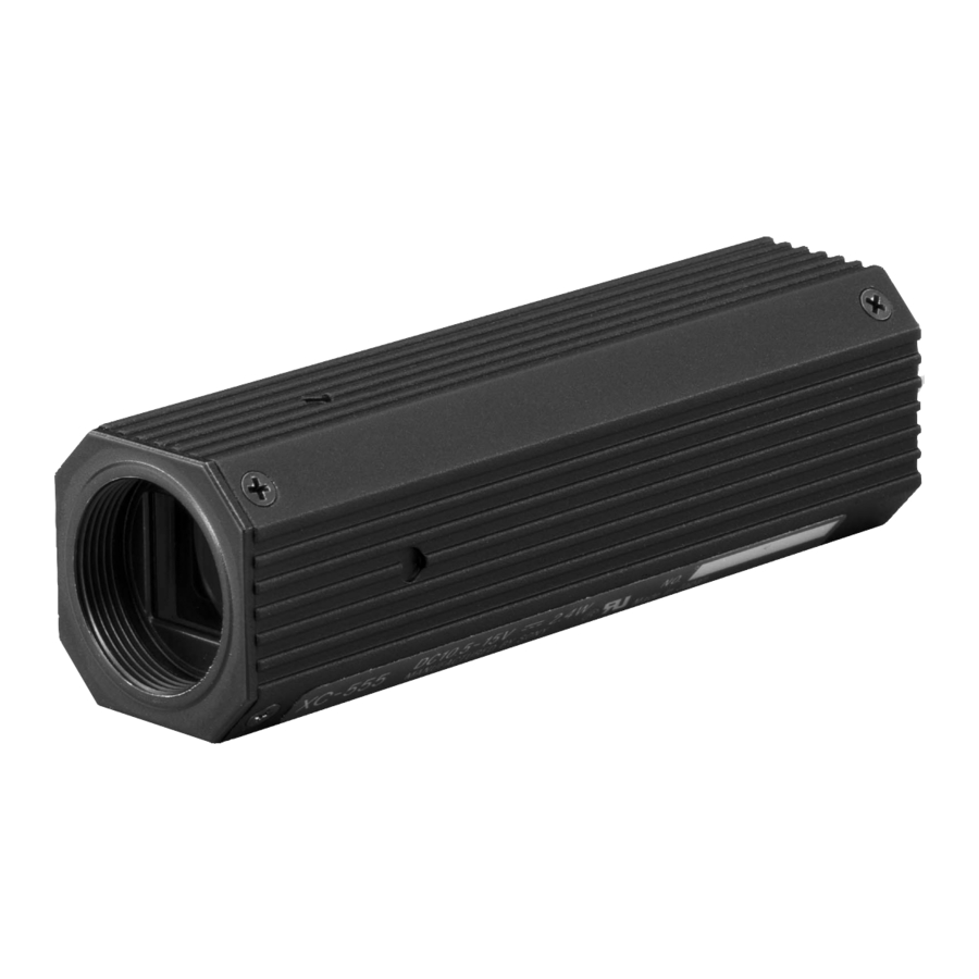
The XC-555/555P is an ultra-small color camera module that utilizes a 1/2inch Charge Coupled Device.
Ultra-small size and lightweight
The camera is so small and light that you can install it anywhere: even in locations where conventional video cameras cannot be installed.
High resolution
A built-in Super HAD (Hole Accumulated Diode) sensor, allows high sensitivity, low smear images. You can shoot, even under poor lighting conditions.
High sensitivity
With a CCD offering 380,000 effective pixels, high-resolution images can be obtained.
Four white balance adjustment modes
Using the white balance DIP switches, you can choose from among four white balance modes (3200K/5600K/ATW/MAN) to choose the best settings for shooting conditions, and the most appropriate color compensation.
Electronic shutter with a wide range of operating speeds
Using the electronic shutter DIP switches, these levels of shutter speed (OFF, 1/100, and FLICKERLESS) are available to allow you to match the shutter speed to the shooting conditions.
When you set the DIP switches for the CCD IRIS function, the shutter speed is adjusted automatically, based on the amount of light allowed to enter, ensuring the most appropriate level of image signal.
Location and Function of Parts (Fig. A)

 Dip switches for setting functions
 WHITE BALANCE
Select the white balance setting according to the lighting conditions.
| Lighting condition | DIP switch setting | |
| 3200K (fixed) | For indoor shooting under incandescent light (factory setting). |  |
| 5600K (fixed) | For outdoor shooting on sunny days. |  |
| ATW (auto tracing white balance) | The white balance is adjusted according to the color temperature transition of the subject. This mode is suitable for shooting with variable lighting. |  |
| MAN (manual) | Select this position when you want to adjust the red color with the R control and the blue color with the B control. |  |
 Shutter speed
Set the shutter speed switches to select the desired shutter speed. Using the CCD IRIS function, set the CCD IRIS mode.
| Shutter speed | DIP switch setting | |
| OFF | 1/60 sec. (factory setting) |  |
| 1/1000 | 1/1000 sec. |  |
| CCD IRIS | Set the CCD IRIS mode. When using the RGB adaptor exposure time control function, make sure it is set in this position. |  |
| FLICKERLESS | 1/100 sec. |  |
 AGC (auto gain control) ON/OFF
| Gain | DIP switch setting | |
| ON | Auto gain control (factory setting) |  |
| OFF | 0 dB |  |
 Y/C/VBS
Select the camera output signal.
| Output signal | DIP switch setting | |
| Y/C | Select this position to output the Y/C separated signal from the DC IN/VIDEO connector. |  |
| VBS | Select this position to output the VBS signal from the DC IN/ VIDEO (factory setting). |  |
 R control for manual white balance adjustment
This control is effective when the white balance switches are set to MAN. Adjust the red color by turning the control with the supplied screwdriver.
 B control for manual white balance adjustment
This control is effective when the white balance switches are set to MAN. Adjust the blue color by turning the control with the supplied screwdriver.
 DC IN/SYNC/VIDEO connector (multi 12-pin) (See Fig. B)

This connector inputs DC 12V power and outputs the video signal when the CCXC-12P02N/12P05N/12P10N/12P25N camera cable is connected. If the unit is connected to devices that originate a synchronized signal, the external synchronous signal (VS, HD/VD) can be used to move the color camera module.
| Signal | Sync signal types | ||
| External Sync signal | Internal Sync signal | ||
| Pin No. | HD,VD | HD,VD | |
| 1 | GND (Earth) | GND (Earth) | GND (Earth) |
| 2 | +12V | +12V | +12V |
| 3 | VBS Output (Earth) | VBS Output (Earth) | VBS Output (Earth) |
| 4 | VBS Output (signal) | Y Output (signal) | VBS Output/Y Output (signal) |
| 5 | HD Input (Earth) | - | - |
| 6 | HD Input (signal) | - | - |
| 7 | VD Input (signal) | VS Input (signal) | - |
| 8 | GND ( /C) | GND ( /C) | GND ( /C) |
| 9 | /C Output (signal) | /C Output (signal) | /C Output (signal) |
| 10 | - | - | - |
| 11 | - | - | - |
| 12 | VD Input (Earth) | VS Input (Earth) | GND |
 Lens mount (special mount)
Installation
Usable Lenses
- VCL-12S12XM special mount lens (f=12mm)
- VCL-06S12XM special mount lens (f=6mm)
- VCL-03S12XM special mount lens (f=3.5mm)
- VCL-12SXM special mount lens (f=12mm)
- C-mount lens
Half-inch C-mount lens (It should stand out less than 4.1 mm from the lens mount shoulder). When a C-mount type lens is attached, a C-mount adaptor (LO-999CMT) is required.(See Fig. C)


Notes
- This camera uses a 1/2-inch CCD. So the lens should be used with this size of CCD. If used with a lens intended for 2/3-inch CCD, the angle of view will be different.
- When connecting a heavy lens, make sure that it is supported properly.
- When connecting heavy lens, make sure that it is not subject to shocks or vibration.
Attaching the Lens (Fig. D)

- Remove the lens mount cap by turning it counterclockwise.
- Screw the C-mount adaptor into the lens mount of the camera. (only when using a C-mount lens)
- Screw the lens.
Notes
- You can mount a C-mount auto-iris lens, as long as it does not project more than 4.1 mm from the lens mount shoulder.
- The plug is very small and fragile. Take special care when handling it.
- Do not pull the lens cord connected to the lens adaptor. If you do, the plug or camera lens connector may be damaged.
Installing the Camera on a Tripod (Fig. E)

When mounting the camera on a tripod, use the supplied tripod adaptor.
- Assemble the tripod adaptor parts.
- Mount the video camera module on the tripod adaptor.
Connections (Fig. F)

An example of the assembly of the DC700 Camera Adaptor.
Notes
- Make sure to turn off the power to the units you are connecting or their components may be damaged.
- When disconnecting the cord, pull it out by the plug. Never pull the cord itself.
- Connect the power cord after completing all other connections.
Genlock
The color video camera module is designed so that internal sync and external sync are switched automatically. When the color video camera module receives the following external sync signal, the camera is synchronized to that external sync signal.
| Connection example | External sync signal | ||
| HD/VD | VS | VBS | |
| Connection of the camera and the DC700. | Genlock | No genlock | |
CCD Characteristics
The following conditions that may be observed during the use of a CCD video camera are not associated with any fault of the camera.
Smearing
The picture may be smeared when a very bright object is shot. (See Fig. G)

Patterned noise
This may appear over the entire monitor screen when the camera is operated at a high temperature.
Jagged picture
When stripes, straight lines, or the like are shot, the image monitored on the screen may appear jagged.
Specifications
Pickup device
Pickup device: Interline transfer 1/2-inch CCD
Color filter: Complementary color mosaic
Total picture elements: XC-555: 768(H) × 494(V), XC-555P: 752(H) × 582(V)
Sensing area: 4.8 × 3.6 mm
Optical and others
Lens mount: Special mount (NF mount)
Signal system: XC-555: NTSC standard, XC-555P: PAL standard
Scanning system: XC-555: 525 lines, 2:1 interlace, 30 frames/sec., XC-555P: 625 lines, 2:1 interlace, 25 frames/sec.
Sync system: Internal/External (automatic switching)
External synchronous input: HD/VD, VS
Horizontal resolution: XC-555: 470 TV lines, XC-555P: 460 TV lines
Minimum illumination: 4.5 lux at F1.2 AGC: ON
Sensitivity: 2000 lux at F5.6 AGC: OFF (0 dB)
Video output: VBS/Y/C (selected with the switch)
VBS: 1 Vp-p, 75 ohms, sync negative
Y: 1 Vp-p, 75 ohms
C: C level depends on the composite video out signal
Video signal to noise ratio: XC-555: 48 dB (standard) AGC: OFF (0 dB), XC-555P: 46 dB (standard) AGC: OFF (0 dB)
Shutter speed: 4 speeds selectable: 1/60 sec. (OFF), 1/1000 sec., CCD IRIS, and FLICKERLESS
White Balance: 4 modes selectable: ATW (auto white tracing balance), 3200K, 5600K, and MAN (manual)
Gain control: 2 modes selectable: AGC and fixed (0 dB)
Output connect: DC IN/SYNC/VIDEO: multi 12-pin LENS: 3-pin
Power requirement: 10.5 to 15 V DC
Power consumption: 2.5 W
Operating temperature: 0°C to 40°C (32°F to 104°F)
Storage temperature: –20°C to 60°C (–4°F to 140°F)
Operating humidity: 20 to 80% (no condensation permissible)
Storage humidity: 20 to 90% (no condensation permissible)
Shock resistance: Less than 70G
Dimensions: 22 × 22 × 75 (mm) (w/h/d)(7/8 × 7/8 × 2 15/16 inches)
Mass: 75g (4 oz)
Accessories supplied:
Lens mount cap (1)
Tripod adaptor (1 set)
Screwdriver (1)
Label (1)
Operating Instructions (1)
Accessories not supplied
Camera adaptor: DC-700
Special mount lens:
VCL-12S12XM (f=12 mm)
VCL-06S12XM (f=6 mm)
VCL-03S12XM (f=3.5 mm)
VCL-12SSXM (f=12 mm)
C-mount Adaptor: LO-999CMT
Extension ring kit: LO-999ERK
12-pin camera cable: CCXC-12P02N/12P05N/12P10N/12P25N
Design and specifications are subject to change without notice.
Sony Corporation © 2001 Printed in Japan

Documents / ResourcesDownload manual
Here you can download full pdf version of manual, it may contain additional safety instructions, warranty information, FCC rules, etc.
Download SONY XC-555/P - CCD Color Video Camera Module Operating Instructions
Advertisement


Need help?
Do you have a question about the XC-555 and is the answer not in the manual?
Questions and answers