
Related Manuals for Bove Technology B9 VW


Summary of Contents for Bove Technology B9 VW
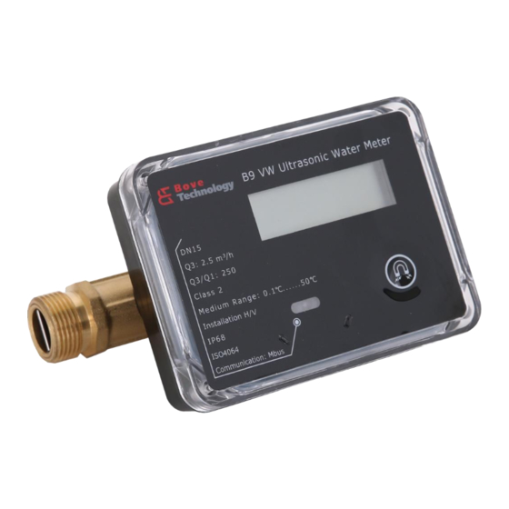
- Page 1 Installation & User Guide B9 VW Ultrasonic Water Meter Read this Guide before installing the meter www.bovetech.com...
- Page 2 Every effort has been made in the preparation of this manual to ensure the accuracy of its contents. However, should you have any questions or find any errors, please contact BOVE TECHNOLOGY. Copying or reproducing all or any part of the contents of this manual without the permission of BOVE TECHNOLOGY is strictly prohibited.
-
Page 3: Table Of Contents
CONTENT 1. GENERAL INFORMATION ......................1 2. TECHNICAL SPECIFICATION ..................... 1 ................................. 1 2.1 F ENSOR ................................2 2.2 C ALCULATOR 2.3 C ..............................2 OMPLETER METER ................................ 4 2.4 D TORAGE 3. INSTALLATION ..........................4 3.1 R ....................4 EQUIREMENTS FOR INSTALLATION ENVIRONMENT 3.2 B ............................ -
Page 4: General Information
The flow meter body is equipped with 2 ultrasonic transducers facing 2 acoustic reflectors. Flow sensor data: Manufacturer Bove Type B9 VW Accuracy class Class 2 16 bar ≤63kPa Max Pressure loss at Q3 Max admissible temperature 50°... -
Page 5: Calculator
2.3 Completer meter Manufacturer Bove Flow Measurement Dimensions (mm) Connection Flow Rate (m Type DN (mm) ――― Length Width Height ″ B9 VW-15 0.01 0.016 3.125 G3/4 ′ B9 VW-20 0.016 0.0256 ″ B9 VW-25 0.025 0.04 7.875 G1 1/4 ″... - Page 6 ′ B9 VW-40 0.064 Pressure Loss △ P ≤63 KPa 1.6 MPa Water temperature range 0.1 to 30° C, 0.1 to 50° C Q3/Q1 250:1 Accuracy Class 2 2 %(at Θ ≤ 30°C) Maximum permissible error in upper ...
-
Page 7: Data Storage
3. Installation 3.1 Requirements for installation environment B9 VW series ultrasonic water meter has been designed for indoor installation in non-condensing environments with ambient temperatures from 5~55°C. The meter must not be under any mechanical stress when installed in the pipe. -
Page 8: Before Installation
min. 25cm between signal cables and other installations. If two or more meters are to be installed shall be in parallel, the axis-center distance between two meters shall be at least 135mm minimum. 3.2 Before Installation Prior to installation of the flow sensor, the pipe shall be thoroughly flushed out, and any dirty, stone alike items must be removed from the pipe. -
Page 9: Installation Of Non-Return Valve
As a standard the meter is delivered with the local time, or destination time if required. 4. Power supply B9 VW Series can be fitted with one ER18505 and ER26500 with operating time of 6/10/15 years respectively. Brand... -
Page 10: Interface & Communication
+85° C 5. Interface & Communication 5.1 IrDA B9 VW Series are all equipped with an optical interface IrDA to IEC62056-21 as a standard. In addition, one of the following options can be ordered for remote output. 5.2 M-BUS Cable: connected with galvanic isolation Voltage: 50V max. -
Page 11: Rs-485(Optional)
Yellow Green 6. Operation & Display B9 VW Series is fitted with an easily readable LCD, including 8 digits, measuring units and information field. The display automatically returns to LCD sleep mode 3 minutes after the latest activation of the push button. When power on, the meter will reset and displays full screen to allow users to detect if there is any problem with the LCD. -
Page 12: Operations On How To Display
Credit alarm Prepaid mode only Button indication Button detected once appear Reverse flow Reverse flow Valve indicate Prepaid mode only Unit Gal Unit Unit Volume and flow rate Wireless communication Reserve Unit Temperature Currency Prepaid mode only Tariff Prepaid mode only 6.1 Operations on how to display Users may press the button to read the meter information such as Accumulated volume, current flow rate, etc. - Page 13 6.1.1 Menu List (User Loop) Pressing the button for 5 seconds and holding it on will bring up the four menus for users to select. Main Menu xxxxx.xxx Keep press more than 5 seconds 6.1.2 Main Menu Shortly pressing the button to display items under the Main Menu one by one in the following order to check the measurement data: Copyright©...
- Page 14 6.1.3 Menu E Shortly pressing the button to display items under Menu E one by one in the following order to check the meter information: Copyright© 2018 Bove Intelligent Technology Co., Ltd 11 / 14...
- Page 15 6.1.4 Menu I This Menu shows history date records of last 24 days/weeks/months. Press the button to select the day/week/month, then flow consumption will be displayed in turn. Copyright© 2018 Bove Intelligent Technology Co., Ltd 12 / 14...
- Page 16 6.1.5 Menu F The following diagram shows Menu F (Calibration mode only). In F mode, Accumulated flow value is able to reset automatically, when flow is zero and starts to exceed the preset value then the current accumulated value is clear to zero. Also the value can be reset by long-pressing the button (over 5 seconds).
-
Page 17: Error And Warning
7. Error and Warning The meter constantly performs self-diagnosis and can display various faults. Visual indication on the LCD display in the event of an warning. Permanent visual indication on the LCD: Fault Meaning How to handle the error Low battery Communication circuit to be checked Empty Pipe Fulfill the pipe with water, no air bubble. - Page 18 All trademarks in this material are property of the respective companies. Bove and the Bove logotype are trademarks of Bove Technology. All rights reserved. Copyright© 2018 Bove Intelligent Technology Co., Ltd...
Need help?
Do you have a question about the B9 VW and is the answer not in the manual?
Questions and answers