
Related Manuals for Bove Technology B9 VW-15


Summary of Contents for Bove Technology B9 VW-15
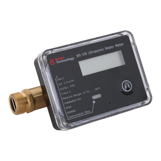
- Page 1 Installation & User Guide B9 VW Ultrasonic Water Meter Read this Guide before installing the meter www.bovetech.com...
- Page 2 BOVE TECHNOLOGY. Copying or reproducing all or any part of the contents of this manual without the permission of BOVE TECHNOLOGY is strictly prohibited. Bove Intelligent Technology Co., Ltd Add: Level 5, Building 5, No. 36,...
-
Page 3: Table Of Contents
CONTENT 1. GENERAL INFORMATION ............................1 2. TECHNICAL SPECIFICATION ........................... 1 ................................1 2.1 F ENSOR ................................2 2.2 C ALCULATOR ..............................2 2.3 C OMPLETER METER ................................4 2.4 D TORAGE 3. INSTALLATION ................................4 ......................4 3.1 R EQUIREMENTS FOR INSTALLATION ENVIRONMENT .............................. -
Page 4: General Information
1. General Information Please note that the following installation conditions must be obeyed: Pressure Requirement: MAP16. Environmental Class: E1, M1 Installation requirement: There must be a distance of minimum 25 cm between signal cables and other installations If medium temperature is below 10°C or above 90°C in flow sensor, It’s recommended that the calculator be wall-mounted. -
Page 5: Calculator
2.3 Completer meter Bove Manufacturer Flow Measurement Dimensions (mm) Connection Flow Rate (m Type DN (mm) Length Width Height ――― G3/4″ B9 VW-15 0.01 0.016 3.125 G1′ B9 VW-20 0.016 0.0256 B9 VW-25 0.025 0.04 7.875 G1 1/4″ B9 VW-32 0.04... - Page 6 Class 2 Accuracy 2 %(at Θ ≤ 30°C) Maximum permissible error in upper flow 3% (at Θ > 30°C) rates range Q Q Q Maximum permissible error in lower flow 5% Q < Q rates range Q 0.001 Scale interval(m...
-
Page 7: Data Storage
2.4 Data Storage Accumulated flow for the current month Note:1 will be registered at 00:00 on the balance day, and the calculator stores the data of last 24/ 120 days/ weeks/ months. Flow correction coefficient (Only stored when manufacturing). Meter ID Balance Date Note:2 to 4 are upgraded as per each command Accumulated flow volume... -
Page 8: Mounting Step
Step 2: Sufficient distance.10×DN straight pipe in upstream and 5×DN straight pipe in downstream. (DN: Diameter) Step 3: The specific seal gasket and connector only supplied by Bove Technology. Step 4: On the two sides of the meter, there should be one filter (if the water is soiled) and two shut-off valves. -
Page 9: Power Supply
Make the segment test, in order to displays all display segments for test purposes. The operating hours are counted from initial connection of the battery. The date is incremented daily. As a standard the meter is delivered with the local time, or destination time if required. 4. -
Page 10: Pulse Output (Optional)
Version/Color Pulse M-Bus (2-wire) Pulse M-Bus Black M-Bus 5.3 Pulse Output (Optional) Pulse output for heat or volume, with 0.6m cable connected, with galvanic isolation Pulse significance: 1 pulse per 100 liter Pulse length: 100 ms (Programmable) Heat / Volume: specify in order or change with service-software Voltage: max. -
Page 11: Nb-Iot (Optional)
5.7 NB-IoT (Optional) LTE Band Each 12h Data transmission 5.8 GPRS (Optional) 2G (GPRS) Operator Data transmission 6. Operation & Display B9 VW Series is fitted with an easily readable LCD, including 8 digits, measuring units and information field. The display automatically returns to LCD sleep mode 3 minutes after the latest activation of the push button. -
Page 12: Operations On How To Display
Credit alarm Prepaid mode only Button indication Button detected once appear Reverse flow Reverse flow Valve indicate Valve control meter only Unit Gal Unit Unit Volume and flow rate Wireless communication Reserve Unit Temperature Currency Prepaid mode only Tariff Prepaid mode only 6.1 Operations on how to display Users may touching off the button by magnet to read the meter information such as accumulated volume, current flow rate, etc. - Page 13 6.1.2 Main Menu Shortly touching off the button to display items under the Main Menu one by one in the following order to check the measurement data: Flow Rate Working Hour Diameter Display Test Short active less than 2 seconds Keep active more than 2 seconds Copyright©...
- Page 14 6.1.3 Menu E Touching off the button for less than 2 seconds to display items under Menu E one by one in the following order to check the meter information: Error Keep Time Low Battery Occur Time Error Keep Time Empty Pipe Occur Time Error Keep Time...
- Page 15 6.1.4 Menu I This Menu shows history date records of last 24 logs. Touching off the button for more than 2 seconds to select the log, then flow consumption will be displayed in turn. Factory ID Meter ID Baud rate, Parity, Modbus ID Firmware Version Date Time...
- Page 16 6.1.5 Menu F The following diagram shows Menu F (Calibration mode only). In F mode, Accumulated flow value is able to reset automatically, when flow is zero and starts to exceed the preset value then the current accumulated value is clear to zero. Also the value can be reset by long-trigger the button (over 2 seconds).
-
Page 17: Error And Warning
7. Error and Warning The meter constantly performs self-diagnosis and can display various faults. Visual indication on the LCD display in the event of an warning. Permanent visual indication on the LCD: Fault Meaning How to handle the error Low battery Communication circuit to be checked Empty Pipe Fulfill the pipe with water, no air bubble. - Page 18 All trademarks in this material are property of the respective companies. Bove and the Bove logotype are trademarks of Bove Technology. All rights reserved. Copyright© 2023 Bove Intelligent Technology Co., Ltd...
Need help?
Do you have a question about the B9 VW-15 and is the answer not in the manual?
Questions and answers