
Related Manuals for Bove Technology B39 VW Bulk


Summary of Contents for Bove Technology B39 VW Bulk
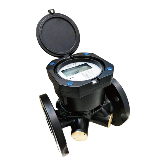
- Page 1 Installation & User Guide B39 VW Bulk Ultrasonic Water Meter Read this Guide before installing the meter www.bovetech.com...
- Page 2 Every effort has been made in the preparation of this manual to ensure the accuracy of its contents. However, should you have any questions or find any errors, please contact BOVE TECHNOLOGY. Copying or reproducing all or any part of the contents of this manual without the permission of BOVE TECHNOLOGY is strictly prohibited.
-
Page 3: Table Of Contents
CONTENT 1. GENERAL INFORMATION ....................... 1 2. TECHNICAL SPECIFICATION ......................1 ................................1 2.1 F ENSOR 2.2 C ................................2 ALCULATOR ..............................2 2.3 C OMPLETER METER ................................. 4 2.4 D TORAGE ............................. 5 2.5 P HYSICAL DIMENSIONS 3. INSTALLATION ........................... 5 .................... -
Page 4: General Information
1. General Information Please note that the following installation conditions must be obeyed: Pressure Requirement: MAP16. Environmental Class: E1, M1 Installation requirement: There must be a distance of minimum 25 cm between signal cables and other installations If medium temperature is below 10°C or above 90°C in flow sensor, It’s recommended that the calculator be wall-mounted. -
Page 5: Calculator
Climatic and mechanical class Electromagnetic class Mechanical class 2.2 Calculator The calculator is a device that calculates the flow volume consumed based on signals from flow sensor. It’s also the control, display and data store part for the meter. Calculator specification: Manufacturer Bove Climatic and mechanical class... - Page 6 1.25 312.5 8*M20 5.12 12*M20 5.04 8.06 787.5 12*M24 12.8 1000 1250 12*M24 12.8 20.5 1600 2000 16*M27 Pressure Loss △ P ≤63 KPa 1.0 MPa Water temperature range 0.1 to 30° C,0.1 to 50° C ~ : DN50 DN150 Q3/Q1(125 or 200) Q3/Q1 DN150~DN400: Q3/Q1=125...
-
Page 7: Data Storage
Storage temperature -20 ~ 60° C Protection Class IP68 Data history 24 month Interface & Communication M-Bus RS485 Output signal for normal operation Infrared Lora (Optional) Output display/signal for M-bus, Infrared testing Power Supply Battery One 3.6V Lithium Battery ≥ 6 Years Battery Life 24V DC External supply for special version (Optional) -
Page 8: Physical Dimensions
2.5 Physical dimensions 3. Installation 3.1 Requirements for installation environment B39 VW-M series ultrasonic water meter has been designed for indoor installation in non-condensing environments with ambient temperatures from 5~55°C. The meter must not be under any mechanical stress when installed in the pipe. The meter must be protected against pressure shocks in the pipe. -
Page 9: Installation Specification
3.2 Installation Specification Description Valve Inlet Strainer Water Meter Valve Outlet 3.3 Before Installation The pipe must be completely cleaned before installing the ultrasonic water meter to prevent the debris from damaging the water meter; Ultrasonic water meter is an expensive precision instrument. Care must be taken when transporting. -
Page 10: Common Error Installation Examples
3.4 Common error installation examples If the flange on the pipe is welded, the position reserved for welding is too large, or the unevenness of the flange welding has an angle with the flange of the meter. Do not forcibly tighten the bolt now otherwise the body may be broken. - Page 11 When installing at the “U” tube, install the meter at the lowest position, because the pipe may accumulate air in the high place, causing the meter to be inaccurate or not measurement. (Shown in Figure D). Figure (D) When the meter is installed at the elbow, it must be ensured that the distance between the front straight pipe is ≥5 pipe diameter and the rear straight pipe is ≥3 pipe diameter.
-
Page 12: Installation Of Non-Return Valve
3.5 Installation of Non-Return Valve The meter can be supplied with a non-return valve (if required) on request. The non-return valve must be installed on the water inlet end of meter when installing. 3.6 After the installation The tightness must be proved by pressurizing with cold water, slowly filling the pipe on completion of the installation;... -
Page 13: M-Bus
standard. In addition, one of the following options can be ordered for remote output. 5.2 M-BUS Cable: connected with galvanic isolation Voltage: 50V max. Current: M-Bus loads Addressing: primary or secondary Note: A higher frequency is not allowed and may result in meter malfunction! Data transmission in the compatibility mode (= standard, one data frame) or in the full mode (3 data frames) possible. -
Page 14: Operation & Display
Black Yellow Green 6. Operation & Display B39 VW–M Series is fitted with an easily readable LCD, including 9 digits, measuring units and information field. The LCD will keep display for easy checking the data. Fig.l LCD Display 6.1 Operations on how to display Users may press the button to read the meter information such as Accumulated volume, current flow rate, etc. - Page 15 6.1.2 Main Menu Shortly pressing the button to display items under the Main Menu one by one in the following order to check the measurement data: Copyright© 2018 Bove Intelligent Technology Co., Ltd 12 / 17...
- Page 16 6.1.3 Menu E Shortly pressing the button to display items under Menu E one by one in the following order to check the meter information: Copyright© 2018 Bove Intelligent Technology Co., Ltd 13 / 17...
- Page 17 6.1.4 Menu I This Menu shows history date records of last 24 months. Click the button to select the month, then the month, monthly flow consumption will be displayed in turn. Copyright© 2018 Bove Intelligent Technology Co., Ltd 14 / 17...
- Page 18 6.1.5 Menu F The following diagram shows Menu F (Calibration mode only). In F mode, Accumulated flow value is able to reset automatically, when flow is zero and starts to exceed the preset value then the current accumulated value is clear to zero. Also the value can be reset by long-pressing the button (over 2 seconds).
-
Page 19: Monthly Data
6.2 Monthly Data The calculator stores the following values for 24 months at each end of month - Volume (meter reading) From the month set day display, press the button shortly to enter the previous month's values. The month values can also be read out via the optical interface and other communication ports. - Page 20 All trademarks in this material are property of the respective companies. Bove and the Bove logotype are trademarks of Bove Technology. All rights reserved. Copyright© 2018 Bove Intelligent Technology Co., Ltd...
Need help?
Do you have a question about the B39 VW Bulk and is the answer not in the manual?
Questions and answers