
Related Manuals for Bove Technology B97 VPW Series


Summary of Contents for Bove Technology B97 VPW Series
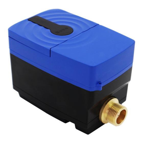
- Page 1 Install ation & User Guid B97 VPW Prepaid Ultrasonic Water Meter Read this Guide before installing the meter www.bovetech.com...
- Page 2 BOVE TECHNOLOGY. Copying or reproducing all or any part of the contents of this manual without the permission of BOVE TECHNOLOGY is strictly prohibited. Bove Intelligent Technology Co., Ltd Add: Level 5, Building 5, No. 36,...
-
Page 3: Table Of Contents
CONTENT 1. GENERAL INFORMATION ............................1 2. TECHNICAL SPECIFICATION ........................... 1 ................................1 2.1 F ENSOR ................................1 2.2 C ALCULATOR ..............................2 2.3 C OMPLETER METER ................................3 2.4 D TORAGE ..............................4 2.5 P HYSICAL DIMENSIONS 3. INSTALLATION ................................4 ...................... -
Page 4: General Information
1. General Information Please note that the following installation conditions must be obeyed: Pressure Requirement: MAP16. Environmental Class: E1, M1 Installation requirement: There must be a distance of minimum 25 cm between signal cables and other installations. Note: Seal or any safety marks on the meter must not be damaged or removed, and doing so will void the warranty and calibration of the meter. -
Page 5: Completer Meter
2.3 Completer meter Bove Manufacturer Dimension DN (mm) Length Height Width G Threaded End Connection G 3/4’ G 1’ Flow Measurement Flow Rate (m /h) @R400 DN (mm) 0.01 0.00625 0.016 0.01 ≤40KPa Pressure Loss △P 1.6 MPa 0.1-30°C (T30) / 0.1-50°C (T50) Water temperature range (Optional) R160 / R200/ R250/ R400 (Optional) -
Page 6: Data Storage
Environmental Requirement E1, M1 Environmental Class 5 ~ 55°C (Indoor and non-condensing) Ambient temperature -20 ~ 60°C Storage temperature IP65/ IP68 Protection Class (Optional) 24/120 logs, daily/ weekly/ monthly. Data history (Optional) Interface & Communication Wired communication RS485/ M-Bus Output signal for normal operation (Optional) Wireless communication LoRaWAN M-Bus, RS485, Infrared... -
Page 7: Physical Dimensions
3. Installation 3.1 Requirements for installation environment B97 VPW series ultrasonic water meter has been designed for indoor installation in non-condensing environments with ambient temperatures from 5~55°C. The meter must not be under any mechanical stress when installed in the pipe. -
Page 8: Mounting Of Flow Sensor
Step 2: Sufficient distance.10×DN straight pipe in upstream and 5×DN straight pipe in downstream. (DN: Diameter) Step 3: The specific seal gasket and connector only supplied by Bove Technology. Step 4: On the two sides of the meter, there should be one filter (if the water is soiled) and two shut-off valves. -
Page 9: After The Installation
26.2×50mm 15.1×21mm Max dimension -60°C ~ +85°C Operating temperature 5. Interface & Communication 5.1 IrDA B97 VPW Series are all equipped with an optical interface IrDA to IEC780 as a standard. 5.2 LoRaWAN (Default) EU433 EU868 IN865 US915 AU915 AS923... -
Page 10: Rs485 (Optional)
12dBm 14dBm 20dBm Transmitting Power Each 6h as default Data transmission 5.3 RS485 (Optional) Cable: connected with four-core cable Voltage: 5-24V. Note: The meter reading interval should be over than 1 hour. Version/Color RS-485 Black Yellow Green 5.4 M-Bus (Optional) Cable: Connected with galvanic isolation, no need to distinguish Voltage: 50V max. -
Page 11: Operation & Display
6. Operation & Display B97 VPW Series is fitted with an easily readable LCD, including 8 digits, measuring units and information field. Fig. LCD Display Icon Name Meaning Calibration mode Under calibration User is reminded to replace the battery Low battery warming with a new one. -
Page 12: Operations On How To Display
6.1 Operations on how to display Users may touching off the button (Hall) to read the meter information such as Accumulated volume, current flow rate, etc. 6.1.1 Measuring Menu List (User Loop) Touching off the hall for more than 2 seconds and holding it on will bring up the four menus for users to select. - Page 13 6.1.2 Main Menu Shortly touching off the hall to display items under the Main Menu one by one in the following order to check the measurement data: Forward Totalizer The balance can be used Last charging Flow Rate Working Hour Diameter Display Test Short trigger less than 2 seconds...
- Page 14 6.1.5 Menu E Shortly touching off the hall to display items under Menu E one by one in the following order to check the meter information: Low Battery Occur Time Error Keep Time Error Keep Time Empty Pipe Occur Time Error Keep Time Reverse Flow Occur Time...
- Page 15 6.1.6 Menu I This Menu shows history date records of last 24 months. Touching off the hall to select the month, then the month, monthly flow consumption will be displayed in turn. Factory ID Meter ID Firmware Version Date Time History Date 1 History Date 2 ……...
- Page 16 6.1.7 Menu F The following diagram shows Menu F (Calibration mode only). In F mode, Accumulated flow value is able to reset automatically, when flow is zero and starts to exceed the preset value then the current accumulated value is clear to zero. Also the value can be reset by long-trigger the hall (over 2 seconds).
-
Page 17: Error And Warning
7. Error and Warning The meter constantly performs self-diagnosis and can display various faults. Visual indication on the LCD display in the event of a warning. Permanent visual indication on the LCD. Fault Meaning How to handle the error Low battery Communication circuit to be checked Empty Pipe Fulfill the pipe with water, no air bubble. - Page 18 All trademarks in this material are property of the respective companies. Bove and the Bove logotype are trademarks of Bove Technology. All rights reserved. Copyright© 2023 Bove Intelligent Technology Co., Ltd...
Need help?
Do you have a question about the B97 VPW Series and is the answer not in the manual?
Questions and answers