Table of Contents
Advertisement
Quick Links
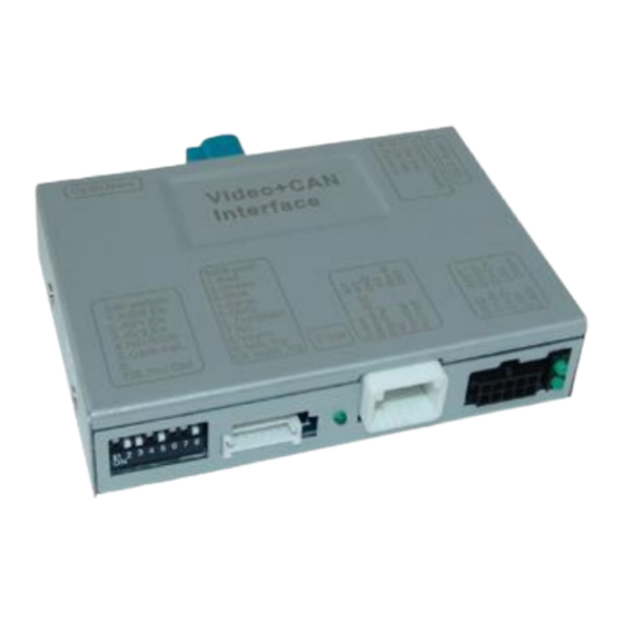
r.LiNK Video-inserter
RL3-SY3
Compatible with Ford vehicles with
Sony Sync3 Touch with 7 or 8inch monitor
Video-inserter for rear-view camera
and two additional video sources
Product features
Video-inserter for factory-infotainment systems
2 CVBS video-inputs for after-market devices (e.g. USB-Player, DVB-T2 tuner)
CVBS Rear-view camera video-input
Automatic switching to rear-view camera input on engagement of the reverse gear
Activatable parking guide lines for rear-view camera (not available for all vehicles)
Video-in-motion (ONLY for connected video-sources)
Video-inputs NTSC and PAL compatible
Version 08.02.2019
CAM(V98)/(V50+V41)
RL3-SY3
Advertisement
Table of Contents

Related Manuals for r.LiNK RL3-SY3


Summary of Contents for r.LiNK RL3-SY3
- Page 1 Video-inserter RL3-SY3 Compatible with Ford vehicles with Sony Sync3 Touch with 7 or 8inch monitor Video-inserter for rear-view camera and two additional video sources Product features Video-inserter for factory-infotainment systems 2 CVBS video-inputs for after-market devices (e.g. USB-Player, DVB-T2 tuner) ...
-
Page 2: Table Of Contents
Case 2: Interface does not receive the reverse gear signal 3.2. Connecting video-interface and keypad 3.3. Picture settings 4. Interface operation 4.1. By infotainment button 4.2. By keypad 5. Specifications 6. FAQ – Trouble Shooting-Interface functions 7. Technical support Version 08.02.2019 CAM(V98)/(V50+V41) RL3-SY3... -
Page 3: Prior To Installation
The place of installation has to be free of moisture and away from heat sources. 1.1. Delivery contents Take down the serial number of the interface and store this manual for support purposes: ____________________ Version 08.02.2019 CAM(V98)/(V50+V41) RL3-SY3... -
Page 4: Checking The Compatibility Of Vehicle And Accessories
The video-interface converts the video signals of connected after-market sources in a factory monitor compatible picture signal which is inserted in the factory monitor, by using separate trigger options. Further it reads the vehicle’s digital signals out of the vehicle’s CAN-bus and converts them for the video interface. Version 08.02.2019 CAM(V98)/(V50+V41) RL3-SY3... -
Page 5: Dip Switch Settings
Note: Dip 1, 4, 6 and 8 are out of function and have to be set to OFF. Version 08.02.2019 CAM(V98)/(V50+V41) RL3-SY3... -
Page 6: Dip - Red
If the necessary stabilized power supply for the interface is not taken directly from the battery, the chosen connection has to be checked for being constantly stabile. The interface needs a permanent 12V source! 2.1. Place of installation The interface is built to be connected behind the vehicle`s head unit. Version 08.02.2019 CAM(V98)/(V50+V41) RL3-SY3... -
Page 7: Connection Schema
2.2. Connection schema Version 08.02.2019 CAM(V98)/(V50+V41) RL3-SY3... -
Page 8: Connecting Picture Signal Cable
Connection to the head unit may cause damage to the system! Note: No liability for vehicle wire colours and pin definition! Changes by the vehicle manufacturer are possible. The given information has to be verified by the installer. Version 08.02.2019 CAM(V98)/(V50+V41) RL3-SY3... -
Page 9: Separate Head Unit With Tablet Monitor
Connection to the head unit may cause damage to the system! Note: No liability for vehicle wire colours and pin definition! Changes by the vehicle manufacturer are possible. The given information has to be verified by the installer. Version 08.02.2019 CAM(V98)/(V50+V41) RL3-SY3... -
Page 10: Connection - Pnp Power / Can Cable
54pin connector of the enclosed PNP Power/CAN cable. Connect the enclosed PNP Power / CAN cable’s opposite female54pin connector to the previously become free male 54pin connector of the monitor. Version 08.02.2019 CAM(V98)/(V50+V41) RL3-SY3... -
Page 11: Separate Head Unit With Tablet Monitor
Connect the single brown cable to the vehicle’s Ground. Note: No liability for vehicle wire colours and pin definition! Changes by the vehicle manufacturer are possible. The given information has to be verified by the installer. Version 08.02.2019 CAM(V98)/(V50+V41) RL3-SY3... -
Page 12: Analog Power Supply
Connect the female 12pin connector of the 12pin interface cable to the male 12pin connector of the video interface. Connect the 12pin interface cable’s red coloured wire ACC-out (max 3A) and the purple coloured wire Manual ACC both to S-contact terminal 86s +12V (e.g. glove compartment illumination). Version 08.02.2019 CAM(V98)/(V50+V41) RL3-SY3... -
Page 13: Connection - Video Sources
Connect the video RCA connector of the rear-view camera to the female RCA connector “Camera-IN” of the 12pin interface cable. Connect the video RCA connectors of additional video sources to the 12pin interface cable’s female RCA connectors „Video IN 1” “Video IN 2”. Version 08.02.2019 CAM(V98)/(V50+V41) RL3-SY3... -
Page 14: After-Market Rear-View Camera
The 12 V power supply for the rear-view camera (max 3A) has to be taken from the 12pin interface cabl’s green wire “Reverse-OUT” to avoid an unnecessary, permanent power supply to the camera electronic. Both green cables “Reverse IN” “Reverse OUT” have to remain connected. Version 08.02.2019 CAM(V98)/(V50+V41) RL3-SY3... -
Page 15: Case 2: Interface Does Not Receive The Reverse Gear Signal
(86) of the relay. Connect the output connector (87) of the relay to the rear-view camera’s power- cable, like you did it to the green “Reverse-IN” cable before. Connect permanent power / 12V to the relay’s input connector (30). Version 08.02.2019 CAM(V98)/(V50+V41) RL3-SY3... -
Page 16: Connecting Video-Interface And Keypad
Connect the keypad’s female 4pin connector to the 12pin interface cable’s male 4pin connector. Note: Even if the switching through several video sources by the keypad mightn’t be required, the keypad’s invisible connection and availability is strongly recommended. Version 08.02.2019 CAM(V98)/(V50+V41) RL3-SY3... -
Page 17: Picture Settings
Position V (vertical) out of function IR-AV1 out of function IR-AV2 out of function Guide-lines left out of function Guide-lines right out of function Guide lines CNTRL out of function (Dip switch 7 for guide lines) Version 08.02.2019 CAM(V98)/(V50+V41) RL3-SY3... -
Page 18: Interface Operation
Switchover by vehicle buttons isn’t possible in all vehicles. In some vehicles the external keypad has to be used. 4.2. By keypad Alternatively or additionally to the factory infotainment buttons, the interface’s external keypad can be used to switch the enabled inputs. Version 08.02.2019 CAM(V98)/(V50+V41) RL3-SY3... -
Page 19: Specifications
Video input 0.7V - 1V Video input formats NTSC / PAL RGB-video amplitude 0.7V with 75 Ohm impedance Temperature range -40°C to +85°C Dimensions video-box 119 x 25 x 103 mm (W x H x D) Version 08.02.2019 CAM(V98)/(V50+V41) RL3-SY3... -
Page 20: Faq - Trouble Shooting-Interface Functions
Camera input picture fluorescent light which shines Test camera under natural light outside the garage. flickers. directly into the camera. Camera input picture is Protection sticker not Remove protection sticker from lens. bluish. removed from camera lens. Version 08.02.2019 CAM(V98)/(V50+V41) RL3-SY3... -
Page 21: Technical Support
Please note that direct technical support is only available for products purchased directly from NavLinkz GmbH. For products bought from other sources, contact your vendor for technical support. NavLinkz GmbH distribution/tech dealer-support Eurotec-Ring 39 D-47445 Moers +49 2841 949970 Email mail@navlinkz.de 10R-03 5384 Made in China Version 08.02.2019 CAM(V98)/(V50+V41) RL3-SY3...
Need help?
Do you have a question about the RL3-SY3 and is the answer not in the manual?
Questions and answers