Table of Contents
Advertisement
Quick Links
Advertisement
Table of Contents

Related Manuals for Rangemaster Nexus SE 110 Induction


Summary of Contents for Rangemaster Nexus SE 110 Induction
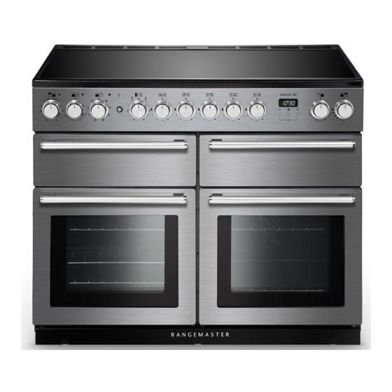
- Page 1 USER GUIDE & INSTALLATION INSTRUCTIONS Nexus SE 110 Induction U110795-02...
- Page 2 Terms & Conditions 1. This is my Rangemaster is open to residents of UK mainland only, aged 18 years & over. 2. All entries should be submitted to the advertised e-mail address, or Rangemaster UK Facebook, Instagram or Twitter page using the advertised hashtag &...
-
Page 3: Table Of Contents
Contents Before you start... Cooking Table Personal safety Cleaning Your Cooker Electrical connection safety Peculiar smells Glide-out Grill™ Ventilation Control Panel and Doors Maintenance Ovens Induction care Cleaning Table Oven care Troubleshooting Oven Shelves (dependant on model) Hob care Installation Cooker care Dear Installer Cooling fan... -
Page 5: Before You Start
Before you start... CAUTION: Your cooker should give you many years of A long term cooking process • trouble-free cooking if installed and operated has to be supervised from time to time. correctly. It is important that you read this A short term cooking process has to be section before you start. - Page 6 Note: The cooker must be connected to the Fig. 1.1 correct electrical supply as stated on the voltage label on the cooker, through a suitable cooker control unit incorporating a double- pole switch, having a contact separation of at least 3 mm in all poles. The cooker MUST NOT be connected to 10 mm²...
-
Page 7: Peculiar Smells
The appliance must be installed in Maintenance • accordance with the regulations in force Only a qualified service engineer • and only in a well ventilated space. should service the appliance and only approved spare parts should be used. It Failure to install the appliance correctly •... -
Page 8: Induction Care
Frost on frozen foods or moisture performance, we recommend the use of on fresh foods can cause hot fat to bubble AGA Rangemaster Induction cookware. up and over the sides of the pan. Carefully If you decide to purchase an alternative... - Page 9 Take care NOT to scratch the surface when • Fig. 1.3 placing cookware on the glass panel. Only certain types of glass, glass-ceramic, • earthenware or other glazed containers are suitable for hotplate cooking; others may break because of the sudden change in temperature.
-
Page 10: Oven Care
We recommend that you avoid wiping • Fig. 1.8 any surface unit areas until they have cooled and the indicator light has gone off. Sugar spills are the exception to this (see ‘Cleaning your Cooker’). After cleaning, use ArtNo.324-0001 Steam burst a dry cloth or paper towel to remove any cleaning cream residue. -
Page 11: Oven Shelves (Dependant On Model)
door glass since they can scratch the is not in use (e.g. tea towels, frying pans surface, which may result in shattering of containing oil). the glass. DO NOT place plastic or aluminium foil, or • Make sure the shelves are pushed firmly plastic containers on the hob. -
Page 12: Cleaning
DO NOT use steel wool, oven cleaning Cleaning • pads or any other materials that will Isolate the electricity supply before • scratch the surface. carrying out any thorough cleaning. Allow the cooker to cool. NEVER store flammable materials in the •... -
Page 13: Cooker Overview
Cooker Overview Fig. 2.1 Your induction cooker (Fig. 2.1) has the following features: Fig. 2.2 5 induction cooking zones Control panel Glide-out grill Programmable multifunction oven Slow cook oven Fan oven The Hob Use only pans that are suitable for induction hobs. We recommend stainless steel, enamelled steel pans or cast iron pans with enamelled bases. -
Page 14: Pan Detector
The very best pans have bases that are very slightly curved Fig. 2.3 up when cold (Fig. 2.3). If you hold a ruler across the bottom you will see a small gap in the middle. When they heat up the metal expands and lies flat on the cooking surface. -
Page 15: Residual Heat Indicator, H
Residual Heat Indicator, H Fig. 2.6 After use, a cooking zone will remain hot for a while as heat dissipates. When a cooking zone is switched off the residual heat indicator symbol [H ], will appear in the display. This shows that the cooking zone temperature is above 60 °C and may still cause burns. -
Page 16: Power Sharing Zones
Power Sharing Zones A & B linked (Fig. 2.8) Fig. 2.8 Power sharing is taking the power from the adjacent zone. For example, if zones C, D and E (Fig. 2.8) are set to power level 9, or set to Power Boost (P) the power level in D or E will adjust in the order it was switched on. -
Page 17: Overheat Function
Overheat Function Fig. 2.14 This function identifies when the temperature of the pan rises rapidly and works to maintain a safe level of pan temperature. It should not interfere with normal cooking. Cookware with bases that become distorted (Fig. 2.2) when heated may interfere with the operation of the Overheat Function. -
Page 18: The Ovens
The Ovens Fan Oven This function operates the fan and the heating The clock must be set to the time of day before the left-hand element around it. An even heat is produced oven will work. See the following section on ‘The Clock’ for throughout the oven, allowing you to cook large instructions on setting the time of day. -
Page 19: The Fan Oven
The Fan Oven Conventional Oven (Top and Base Heat) This function combines the heat from the top and Fan ovens circulate hot air continuously, which means base elements. It is particularly suitable for roasting faster, more even cooking. The recommended cooking and baking pastry, cakes and biscuits. -
Page 20: Operating The Ovens
Operating the Ovens Fig. 2.15 Fan Oven Turn the oven knob to the desired temperature (Fig. 2.15). The oven indicator light will glow until the oven has reached the temperature selected. It will then cycle on and off during cooking. Multifunction Oven The multifunction oven has two controls: a function selector and a temperature setting knob (Fig. -
Page 21: Accessories
Accessories Fig. 2.18 Shelf guard Oven Shelves – Left-hand (Main) Oven The oven shelves (Fig. 2.18) are retained when pulled forward but can be easily removed and refitted. Pull the shelf forward until the back of the shelf is stopped by the shelf stop bumps in the oven sides (Fig. -
Page 22: Using The Glide-Out Grill
Using the Glide-out Grill™ DocAUS.020-0004 - Overview - 110DF - Elan Fig. 3.2 Fig. 3.1 Nearest to the element Middle High Middle Low Furthest from the element Four grill height positions refer to Fig. 3.5 Fig. 3.4 Fig. 3.3 To switch on both elements To switch on the right half element Four grill height positions Fig. -
Page 23: Button Clock
3 Button clock Using the clock Fig. 4.1 You can use the clock to turn the programmable oven on and off. The clock must be set to the time of day before the oven will work. NOTE: When using the timer functions, first set the clock as ArtNo.306-0001 - 3-button clock required before setting the oven temperature. - Page 24 When the ‘stop time’ is reached an alarm will sound and Fig. 4.7 the oven will stop working. The word ‘AUTO’ will flash on the display (Fig. 4.6). Press any button to stop the alarm and return to manual cooking. If the alarm is not stopped, it will stop ArtNo.306-0001 - 3-button clock automatically after 7 minutes.
-
Page 25: Cooking Tips
Cooking Tips Hints on Using Your Induction Cooker General Oven Tips If you have not used an induction cooker before please be The wire shelves should always be pushed firmly to the back aware of the following: of the oven. •... -
Page 26: Cooking Table
Cooking Table The oven control settings and cooking times given in the table below are intended to be used as a Top (T) guide only. Individual tastes may require the temperature to be altered to provide a preferred result. ArtNo.050-0007 Centre (C) Oven shelf positions Food is cooked at lower temperature in a fan oven than in a conventional oven. -
Page 27: Cleaning Your Cooker
Cleaning Your Cooker Isolate the electricity supply before carrying out any Fig. 7.1 major cleaning. Allow the cooker to cool. NEVER use paint solvents, washing soda, caustic cleaners, biological powders, bleach, chlorine based bleach cleaners, coarse abrasives or salt. DO NOT mix different cleaning products – they may react together with hazardous results. -
Page 28: Glide-Out Grill
Glide-out Grill™ Fig. 7.2 The grill pan and trivet should be washed in hot soapy water. Alternatively, the grill pan can be washed in a dishwasher. After grilling meats or any foods that soil, leave to soak for a few minutes immediately after use. Stubborn particles may be removed from the trivet using a nylon brush. -
Page 29: Control Panel And Doors
Control Panel and Doors Fig. 7.6 Avoid using any abrasive cleaners, including cream cleaners. For best results, use a liquid detergent. The same cleaner can also be used on the doors. Alternatively, use a soft cloth wrung out in clean hot soapy water. You can use the same method for cleaning the control panel and knobs. -
Page 30: Cleaning Table
Cleaning Table Cleaners listed (Table 7.1) are available from supermarkets or electrical retailers as stated. For enamelled surfaces use a cleaner that is approved for use on vitreous enamel. Regular cleaning is recommended. For easier cleaning, wipe up any spillages immediately. Hotplate Part Finish... -
Page 31: Troubleshooting
Troubleshooting DocNo.050-0001 - Troubleshooting - Induction GENERIC Interference with and repairs to the hob MUST NOT The cooling fan be carried out by unqualified persons. Do not try The induction hob incorporates a cooling fan. This cooling to repair the hob as this may result in injury and fan is active when either the grill or the oven(s) are on. - Page 32 The oven light is not working Fig. 8.1 The bulb has probably blown. You can buy a replacement bulb (which is not covered under the guarantee) from most electrical stores. Ask for a 40 W – 230 V halogen lamp (G9) (Fig. 8.1). Before removing the existing bulb, turn off the power supply and make sure that the oven is cool.
- Page 33 Oven temperature getting hotter as the cooker gets older If turning the temperature down using the oven control knob has not worked, or has only worked for a short time, then you may need a new thermostat. This should be fitted by a service person.
-
Page 34: Installation
INSTALLATION Check the appliance is electrically safe when you have finished. Installation Dear Installer Location of Cooker Before you start your installation, please complete the details The cooker may be installed in a kitchen/kitchen diner but below, so that, if your customer has a problem relating to NOT in a room containing a bath or shower. -
Page 35: Positioning The Cooker
INSTALLATION Check the appliance is electrically safe when you have finished. Positioning the Cooker Fig. 9.1 Fig. 9.1 and Fig. 9.2 show the minimum recommended distance from the cooker to nearby surfaces. 75 mm 75 mm 650 mm The cooker should not be placed on a base. The hotplate surround should be level with, or above, any adjacent work surface. -
Page 36: Lowering The Two Rear Rollers
INSTALLATION Check the appliance is electrically safe when you have finished. Lowering the Two Rear Rollers Fig. 9.5 To adjust the height of the rear of the cooker, first fit a 13 mm spanner or socket wrench onto the hexagonal adjusting nut (Fig. -
Page 37: Electrical Connection
INSTALLATION Check the appliance is electrically safe when you have finished. Electrical Connection Current Operated Earth Leakage Breakers This appliance must be installed by a suitably qualified The combined use of your cooker and other domestic electrician, in accordance with all relevant British Standards/ appliances may cause nuisance tripping, so we recommend Codes of Practice (in particular BS 7671), or with the relevant that the cooker is protected on an individual RCD (Residual... -
Page 38: 10. Circuit Diagrams
10. Circuit Diagrams Earth On Terminal Block N(6) On Terminal Block N(4) INDUCTION UNIT DISPLAY w/br L(2) L(3) w/br INTERFACE On Terminal Block BOARD w/br w/br w/br The connections shown in the circuit diagram are for single-phase. The ratings are for 230 V 50 Hz. Code Description Code Colour w/br... - Page 39 Oven P095199 P038434 P095199 P095199 The connections shown in the circuit diagram are for single-phase. The ratings are for 230 V 50 Hz. Code Description Code Description Code Colour Grill Front Switch Clock / Timer Blue Grill Energy Regulator Slow Cook Oven Thermostat Brown Grill Element Left Hand Side Slow Cook Oven Front Switch...
-
Page 40: 11. Technical Data
DATA BADGE LOCATION: Cooker back, serial number repeater badge below the oven door opening. COUNTRY OF DESTINATION: GB, IE. Connections Electric 230 / 400 V ~ 50 Hz 3N Dimensions Model Nexus SE 110 Induction Overall height minimum 905 mm maximum 930 mm Overall width 1100 mm Overall depth... - Page 41 Hotplate Efficiency Data Brand Rangemaster Model Identification Nexus SE Size Type Induction Type of Hob Induction Number of electric zones Zone 1 - Ø cm Heating Technology Energy Consumption (ECElectric cooking) - Wh/kg Zone 2 - Ø cm Heating Technology Energy Consumption (ECElectric cooking) - Wh/kg Zone 3 - Ø...
- Page 42 Oven Data Brand Rangemaster Model identification Nexus SE Type of oven Electric Mass Number of cavities Left-hand Efficiency Fuel type Electric Cavity type Multifunction Power - conventional Power - forced air convection Volume Litres Energy consumption (electricity) - conventional kWh / cycle 1.01...
- Page 43 NOTE...
- Page 44 NOTE...
- Page 45 NOTE...
- Page 46 NOTE...
- Page 47 • Has not been repaired by persons or organisations other than those authorised to act on behalf of AGA Rangemaster. Date of Purchase Exceptions: • Items not included under the free 1 year guarantee Installer’s Name &...
- Page 48 Registered Office: c/o Aga Rangemaster, Meadow Lane, Long Eaton, Nottingham, NG10 2GD Rangemaster continuously seeks improvements in specification, design and production of products and thus, alterations take place periodically. Whilst every effort is made to produce up-to-date literature, this brochure should not be regarded as...
Need help?
Do you have a question about the Nexus SE 110 Induction and is the answer not in the manual?
Questions and answers